TV7SXT-5NDMIMO BROADBAND DIGITAL TRANSMISSION SYSTEM
Mikrotikls SIA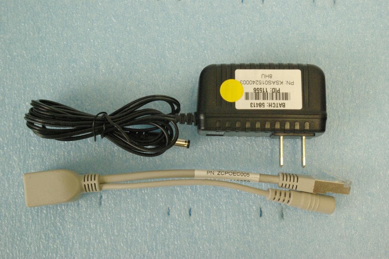
Click to zoom
Application Details
- Equipment Class
- DTS - Digital Transmission System
- Date of Grant
- Feb 04, 2013
- Application Purpose
- Original Equipment
- Date of Application
- Feb 04, 2013
- Equipment Note
- MIMO BROADBAND DIGITAL TRANSMISSION SYSTEM
- Frequency Range
- 5755.00000000 - 5815.00000000
- Company
- Mikrotikls SIA
- Country
- Latvia
Documents & Files
Document Text
Text extracted from the exhibit documents filed with the FCC. Open a document above to read the original.
Users Manual
See www.routerboard.com for more information. Contact [email protected] for support questions. 16-Oct-2012 RouterBOARD SXT 5nD r2 Quick Setup Guide and Warranty Information The RouterBOARD SXT 5nD r2 comes as a complete set, and includes a built in 802.11n dual chain wireless device, and a dual polarization 16dBi antenna. It has one BASE-‐T 10/100 ethernet connector which supports MDI-‐X auto detection. First use 1. Connect an Ethernet cable to the port behind the small plastic door 2. The SXT accepts 24V Passive PoE from a PoE injector 3. The default IP address from LAN is 192.168.88.1 for configuration 4. Username is admin and there is no password Powering The board accepts powering from the Ethernet port (Passive PoE) 8-‐30V DC. Package contains a 24V adapter. Maximum power consumption of the device is 7W. Booting process Initial connection has to be done via the Ethernet cable. Open 192.168.88.1 in your web browser, and choose “Webfig” for browser based configuration or “Winbox” for a Windows utility with the same functions. Username is admin and there is no password. In case IP connection is not available, Winbox can be used to connect to the MAC address of the device. More information here: http://wiki.mikrotik.com/wiki/First_time_startup In case you wish to boot the device from network, for example to use MikroTik Netinstall, hold the RESET button of the device when starting it until the LED light turns off, and Metal will start to look for Netinstall servers. Mounting With the clip pointed forward, slide the mounting bracket into the rail on the bottom of the case, until the clip clicks into place. The SXT comes bundled with a hose clamp -‐ guide the clamp through the opening in the bracket and around the pole where it will be mounted. Tighten the hose clamp screw when alignment is complete. Two screw holes are provided as additional security against accidental bracket movement. The SXT device has a sliding door, behind which the Ethernet port, and the reset jumpers are located. This door can be also secured shut with a screw in the provided screw hole. See www.routerboard.com for more information. Contact [email protected] for support questions. 16-Oct-2012 Buttons and Jumpers • RouterOS reset jumper hole (access through the plastic door) – resets RouterOS software to defaults. Must short cir-‐ cuit the metallic sides of the hole (with a screwdriver, for example) and boot the device. Hold screwdriver in place until RouterOS configuration is cleared. • RouterBOOT reset button (access through the plastic door) has two functions: ü Hold this button during boot time until LED light starts flashing, release the button to reset RouterOS configuration (same result as with reset hole) ü Hold this button during boot time longer, until LED turns off, and then release it to make the device look for Netinstall servers. Operating System Support Currently tested operating system is MikroTik RouterOS (starting from version v5.20). Copyright and Warranty Information Copyright and Trademarks. Copyright MikroTikls SIA. This manual contains information protected by copyright law. No part of it may be reproduced or transmitted in any form without prior written permission from the copy-‐ right holder. RouterBOARD, RouterOS, RouterBOOT and MikroTik are trademarks of MikroTikls SIA. All trademarks and registered trademarks appearing in this manual are the property of their respective holders. Hardware. MikroTikls SIA warrants all RouterBOARD series equipment for the term of fifteen (15) months from the shipping date to be free of defects in materials and workmanship under normal use and service, except in case of damage caused by mechanical, electrical or other accidental or intended damages caused by improper use or due to wind, rain, fire or other acts of nature. If you have purchased your product from a MikroTik Reseller, please contact the Reseller company regarding all warranty and repair issues, the following instructions apply ONLY if you purchased your equipment directly from MikroTik Latvia To return failed unit or units to MikroTikls you must perform the following RMA (Return Material Authorization) procedure. Follow the instructions below to save time, efforts, avoid costs, and improve the speed of the RMA process. Take into account that all goods have one year warranty. Instructions are located on our webpage here: http://rma.mikrotik.com Manual. This manual is provided “as is” without a warranty of any kind, expressed or implied, including, but not limited to, the implied warranty of merchantability and fitness for a particular purpose. The manufacturer has made every effort to ensure the accuracy of the contents of this manual; however, it is possible that it may con-‐ tain technical inaccuracies, typographical or other errors. No liability is assumed for any inaccuracy found in this publication, nor for direct or indirect, incidental, consequential or other damages that may result from such an inaccuracy, including, but not limited to, loss of data or profits. Please report any inaccuracies found to sup-‐ [email protected] See www.routerboard.com for more information. Contact [email protected] for support questions. 16-Oct-2012 Federal Communication Commission Interference Statement (FCC ID: TV7SXT-5ND) This equipment has been tested and found to comply with the limits for a Class B digital device, pur-‐ suant to Part 15 of the FCC Rules. These limits are designed to provide reasonable protection against harmful interference in a residential installation. This equipment generates, uses and can radiate radio frequency energy and, if not installed and used in accord-‐ ance with the instructions, may cause harmful interference to radio communications. However, there is no guar-‐ antee that interference will not occur in a particular installation. If this equipment does cause harmful interfer-‐ ence to radio or television reception, which can be determined by turning …
Text truncated - open the document above for the full version.
Cover Letter(s)
November 23, 2011 Federal Communications Commission Equipment Approval Services Post Office Box 358315 Pittsburgh, Pennsylvania 15215-5315 To Whom It May Concern: Please be advised that SIA "Mikrotikls" has authorized Scot Rogers of Rogers Labs, Inc. to act on behalf in all matters relating to application for equipment authorization, including the signing of all documents relating to these matters and submittals. All acts carried out by Rogers Labs, Inc. on our behalf shall have the same effects as our own. Rogers Labs, Inc. is authorized to receive and exchange data between our company and the Commission. This Authorization is made pursuant to Paragraph 2.911 of FCC Rules CFR 47. This Authorization is in effect until otherwise notified in writing. Name: Edmunds Zvegincevs Title: Project Engineer Signature of applicant: SIA "Mikrotīkls" VAT # LV40003286799 Billing addr.: Aizkraukles iela 23, LV-1006, Rīga Office addr.: Pērnavas iela 46, LV-1009, Rīga Phone: +371 7317700 Fax: +371 7317701
Cover Letter(s)
January 29, 2013 Timco Engineering Inc. 849 NW State Road 45 Newberry, FL 32669 Office of Engineering and Technology Federal Communications Commission Columbia, MD 21046 Applicant: Mikrotikls SIA Pernavas 46 Riga, Latvia LV-1009 Re: Confidentiality for submittal information regarding FCC ID number TV7SXT-5ND PRODUCT: Broadband Digital Transmission System operating under CFR47 part 15.247 Dear Sirs: Mikrotikls SIA requests that the material in the Schematics, Block Diagram, and Operational Description be withheld from public disclosure pursuant to Sections 0.457 and 0.459 of the Commission’s Rules following grant of the application. In support of this request, Mikrotikls submits the following: Long Term Confidential Files Include Schematics File Name Conf Schem RBSXT5nDr2.pdf Block Diagram File Name Conf BlkDia RBSXT5nDr2.pdf Operational Description File Name Conf OpDes RBSXT5nDr2.pdf 1. Identification of the specific information for which confidential treatment is sought: The materials set forth in the Operational Description, block diagram, and Schematics, which are segregated from the non-confidential exhibits of the application, are those for which confidentiality is sought. 2. Identification of the Commission proceeding in which the information was submitted or a description of the circumstances giving rise to the submission: The proceeding is that involving the application for equipment authorization (certification) under FCC ID No: TV7SXT-5ND 3. Explanation of the degree to which the information is commercial or financial, or contains a trade secret or is privileged: This material includes a detailed theory of operation, circuit diagrams, (schematic diagrams) and any detail Parts List. As such, this material is treated as highly confidential business information. ROGERS LABS, INC. 4405 West 259 th Terrace Louisburg, KS 66053 4. Explanation of the degree to which the information concerns a service that is subject to competition: The material for which confidentiality is sought is employed in the design and manufacture of this transmitting equipment that is offered on a highly competitive basis. Customers for this equipment have a variety of competing sources. 5. Explanation of how disclosure of the information could result in substantial competitive harm: Disclosure would, in effect, give away the fruits of the labors of Mikrotik engineering personnel, who have designed the equipment and the manufacturing process. Disclosure would also offer competitors additional unwarranted insight into the state of the product development, thereby allowing competitors an advantage, not available to Mikrotikls SIA 6. Identification of any measures taken by the submitting party to prevent unauthorized disclosure: The information for which confidential treatment is sought is kept confidential by Mikrotikls SIA and not made available to third parties except pursuant to non-disclosure agreements. 7. Identification of whether the information is available to the public and the extent of any previous disclosure of the information to third parties: To the knowledge of those preparing this application, the information has not been disclosed publicly heretofore. While the general theory of operation of this equipment has been the subject of numerous disclosures in industry and standards groups as well as in rule making proceedings of the FCC, the protection sought is narrowly drawn and pertains to certain specific implementations of this radio technology. 8. Justification of the period during which the submitting party asserts that the material should not be available for public disclosure: This material should not be disclosed for at least 25 years. While improvements in design are made relatively frequently, disclosure of the design information would lead to insights into both design and manufacturing techniques that could have an adverse competitive effect for many years to come. As such, it is important that the design not be made available to unauthorized persons who might attempt to use knowledge of the design to compromise the applications for which the equipment will be employed. Should you require any further information, please contact the undersigned. Thank you for your consideration in this matter. Sincerely, Scot Rogers
Cover Letter(s)
January 29, 2013 Timco Engineering Inc. 849 NW State Road 45 Newberry, FL 32669 Federal Communications Commission Equipment Approval Services P.O. Box 35815 Pittsburgh, PA 15251-3315 Applicant: Mikrotikls SIA Pernavas 46 Riga, Latvia LV-1009 Equipment: FCC ID: TV7SXT-5ND FCC Rules: Part 15.247 Digital Transmission System approval Men: The form 731 and application have been electronically submitted and any attachments will be up loaded to your site to be used in obtaining grant of certification. Permanent Mikrotikls SIA requests that the material in the Schematics, Block Diagram, and Operational Description be withheld from public disclosure pursuant to Sections 0.457 and 0.459 of the Commission’s Rules following grant of the application. Schematics File Name Conf Schem RBSXT5nDr2.pdf Block diagram File Name Conf BlkDia RBSXT5nDr2.pdf Operational Description File Name Conf OpDes RBSXT5nDr2.pdf Should you require any further information, please contact the undersigned. Thank you for your consideration in this matter. Sincerely, Scot Rogers Rogers Labs, Inc. Enclosures ROGERS LABS, INC. 4405 West 259 th Terrace Louisburg, KS 66053 Phone / Fax (913) 837-3214
External Photos
Rogers Labs, Inc. Mikrotikls SIA 4405 W. 259th Terrace Model: RouterBOARD SXT 5nD r2 SN: 3B5501DDAF1/236 Louisburg, KS 66053 Test #: 120917 FCC ID#: TV7SXT-5ND Phone/Fax: (913) 837-3214 Test to: CFR47 (15.247) Date: January 29, 2013 Revision 1 File: ExtPho RBSXT5nDr2 Page 1 of 2 External photographs of equipment under test Rogers Labs, Inc. Mikrotikls SIA 4405 W. 259th Terrace Model: RouterBOARD SXT 5nD r2 SN: 3B5501DDAF1/236 Louisburg, KS 66053 Test #: 120917 FCC ID#: TV7SXT-5ND Phone/Fax: (913) 837-3214 Test to: CFR47 (15.247) Date: January 29, 2013 Revision 1 File: ExtPho RBSXT5nDr2 Page 2 of 2
ID Label/Location Info
Rogers Labs, Inc. Mikrotikls SIA 4405 W. 259th Terrace Model: RouterBOARD SXT 5nD r2 SN: 3B5501DDAF1/236 Louisburg, KS 66053 Test #: 120917 FCC ID#: TV7SXT-5ND Phone/Fax: (913) 837-3214 Test to: CFR47 (15.247) Date: January 29, 2013 Revision 1 File: LabelSmpl RBSXT5nDr2 Page 1 of 1 Label and Placement Label
Internal Photos
Rogers Labs, Inc. Mikrotikls SIA 4405 W. 259th Terrace Model: RouterBOARD SXT 5nD r2 SN: 3B5501DDAF1/236 Louisburg, KS 66053 Test #: 120917 FCC ID#: TV7SXT-5ND Phone/Fax: (913) 837-3214 Test to: CFR47 (15.247) Date: February 4, 2013 Revision 1 File: IntPho RBSXT5nDr2 Page 1 of 3 Internal photograph of Transmitter with shielding placed on transmit chains Shield removed for photograph Transmitter chains Rogers Labs, Inc. Mikrotikls SIA 4405 W. 259th Terrace Model: RouterBOARD SXT 5nD r2 SN: 3B5501DDAF1/236 Louisburg, KS 66053 Test #: 120917 FCC ID#: TV7SXT-5ND Phone/Fax: (913) 837-3214 Test to: CFR47 (15.247) Date: February 4, 2013 Revision 1 File: IntPho RBSXT5nDr2 Page 2 of 3 Bottm side of transmit PCB (located below Antenna which has been removed for photograph) Antenna Connections Transmit PCB located below antenna Rogers Labs, Inc. Mikrotikls SIA 4405 W. 259th Terrace Model: RouterBOARD SXT 5nD r2 SN: 3B5501DDAF1/236 Louisburg, KS 66053 Test #: 120917 FCC ID#: TV7SXT-5ND Phone/Fax: (913) 837-3214 Test to: CFR47 (15.247) Date: February 4, 2013 Revision 1 File: IntPho RBSXT5nDr2 Page 3 of 3 EUT as placed inside enclosure
Parts List/Tune Up Info
RouterBOARD SXT 5nD r2 802.11a/n WLAN router Tuning procedure Each units TX and RX functionality is tested and judged with a pass/fail criteria during production. Units meeting the criteria continue through production and others are returned for diagnostics.
RF Exposure Info
Rogers Labs, Inc. Mikrotikls SIA 4405 W. 259th Terrace Model: RouterBOARD SXT 5nD r2 SN: 3B5501DDAF1/236 Louisburg, KS 66053 Test #: 120917 FCC ID#: TV7SXT-5ND Phone/Fax: (913) 837-3214 Test to: CFR47 (15.247) Date: January 29, 2013 Revision 1 File: RFExp RBSXT5nDr2 Page 1 of 1
Test Report
NVLAP Lab Code 200087-0 Rogers Labs, Inc. Mikrotikls SIA 4405 W. 259th Terrace Model: RouterBOARD SXT 5nD r2 SN: 3B5501DDAF1/236 Louisburg, KS 66053 Test #: 120917 FCC ID#: TV7SXT-5ND Phone/Fax: (913) 837-3214 Test to: CFR47 (15.247) Date: January 29, 2013 Revision 1 File: Mikrotikls RBSXT5nDr2 TstRpt 120911 Page 1 of 32 APPLICATION SUBMITTAL TEST REPORT FOR GRANT OF CERTIFICATION FOR Model: RouterBOARD SXT 5nD r2 5745-5825 MHz Broadband Digital Transmission System FCC ID: TV7SXT-5ND FOR MIKROTIKLS SIA Pernavas 46 Riga, Latvia LV-1009 Test Report Number: 120917 Authorized Signatory: Scot D. Rogers NVLAP Lab Code 200087-0 Rogers Labs, Inc. Mikrotikls SIA 4405 W. 259th Terrace Model: RouterBOARD SXT 5nD r2 SN: 3B5501DDAF1/236 Louisburg, KS 66053 Test #: 120917 FCC ID#: TV7SXT-5ND Phone/Fax: (913) 837-3214 Test to: CFR47 (15.247) Date: January 29, 2013 Revision 1 File: Mikrotikls RBSXT5nDr2 TstRpt 120911 Page 2 of 32 Engineering Test Report For Grant of Certification Application FOR CFR 47, PART 15C - Intentional Radiators CFR 47 Paragraph 15.247 License Exempt Intentional Radiator For MIKROTIKLS SIA Pernavas 46 Riga, Latvia LV-1009 Broadband Digital Transmission System Model: RouterBOARD SXT 5nD r2 Frequency Range 5745-5825 MHz FCC ID#: TV7SXT-5ND Test Date: September 17, 2012 Certifying Engineer: Scot D. Rogers Rogers Labs, Inc. 4405 West 259 th Terrace Louisburg, KS 66053 Telephone/Facsimile: (913) 837-3214 This report shall not be reproduced except in full, without the written approval of the laboratory. This report must not be used by the client to claim product endorsement by NVLAP, NIST, or any agency of the U.S. Government. ROGERS LABS, INC. 4405 West 259 th Terrace Louisburg, KS 66053 Phone / Fax (913) 837-3214 NVLAP Lab Code 200087-0 Rogers Labs, Inc. Mikrotikls SIA 4405 W. 259th Terrace Model: RouterBOARD SXT 5nD r2 SN: 3B5501DDAF1/236 Louisburg, KS 66053 Test #: 120917 FCC ID#: TV7SXT-5ND Phone/Fax: (913) 837-3214 Test to: CFR47 (15.247) Date: January 29, 2013 Revision 1 File: Mikrotikls RBSXT5nDr2 TstRpt 120911 Page 3 of 32 Table Of Contents TABLE OF CONTENTS .................................................................................................. 3 REVISIONS ..................................................................................................................... 4 FORWARD ..................................................................................................................... 5 OPINION / INTERPRETATION OF RESULTS ............................................................... 5 ENVIRONMENTAL CONDITIONS.................................................................................. 5 EQUIPMENT TESTED .................................................................................................... 5 APPLICATION FOR CERTIFICATION ........................................................................... 6 APPLICABLE STANDARDS & TEST PROCEDURES .................................................. 7 EQUIPMENT FUNCTION AND CONFIGURATION ........................................................ 7 Equipment Configuration.................................................................................................................................... 8 TEST SITE LOCATIONS ................................................................................................ 8 UNITS OF MEASUREMENTS ........................................................................................ 8 TEST PROCEDURES ..................................................................................................... 9 AC Line Conducted Emission Test Procedure .................................................................................................. 9 Diagram 1 Test arrangement for Conducted emissions .................................................................................... 9 RADIATED EMISSION TEST PROCEDURE ............................................................... 10 Diagram 2 Test arrangement for radiated emissions of tabletop equipment ................................................ 11 Diagram 3 Test arrangement for radiated emissions tested on Open Area Test Site (OATS) .................... 12 LIST OF TEST EQUIPMENT ........................................................................................ 13 INTENTIONAL RADIATORS ........................................................................................ 14 Antenna Requirements ...................................................................................................................................... 14 Restricted Bands of Operation .......................................................................................................................... 14 NVLAP Lab Code 200087-0 Rogers Labs, Inc. Mikrotikls SIA 4405 W. 259th Terrace Model: RouterBOARD SXT 5nD r2 SN: 3B5501DDAF1/236 Louisburg, KS 66053 Test #: 120917 FCC ID#: TV7SXT-5ND Phone/Fax: (913) 837-3214 Test to: CFR47 (15.247) Date: January 29, 2013 Revision 1 File: Mikrotikls RBSXT5nDr2 TstRpt 120911 Page 4 of 32 Restricted Bands Data (General Radiated Emissions) ....................................................................................... 14 Summary of Results for Radiated Emissions in Restricted Bands ................................................................ 15 AC Line Conducted Emissions Procedure ....................................................................................................... 15 Figure One AC Line Conducted Emissions Line 1............................................................................................ 16 Figure Two AC Line Conducted Emissions Line 2 ........................................................................................... 16 AC Line Conducted Emissions Data (Highest Emissions) ................................................................................ 17 Summary of Results for AC Line Conducted Emissions ............................…
Text truncated - open the document above for the full version.
Test Setup Photos
Rogers Labs, Inc. Mikrotikls SIA 4405 W. 259th Terrace Model: RouterBOARD SXT 5nD r2 SN: 3B5501DDAF1/236 Louisburg, KS 66053 Test #: 120917 FCC ID#: TV7SXT-5ND Phone/Fax: (913) 837-3214 Test to: CFR47 (15.247) Date: January 29, 2013 Revision 1 File: TSup RBSXT5nDr2 Page 1 of 3 Test setup photographs AC Line Conducted Emissions Rogers Labs, Inc. Mikrotikls SIA 4405 W. 259th Terrace Model: RouterBOARD SXT 5nD r2 SN: 3B5501DDAF1/236 Louisburg, KS 66053 Test #: 120917 FCC ID#: TV7SXT-5ND Phone/Fax: (913) 837-3214 Test to: CFR47 (15.247) Date: January 29, 2013 Revision 1 File: TSup RBSXT5nDr2 Page 2 of 3 Radiated Emissions General Emissions Rogers Labs, Inc. Mikrotikls SIA 4405 W. 259th Terrace Model: RouterBOARD SXT 5nD r2 SN: 3B5501DDAF1/236 Louisburg, KS 66053 Test #: 120917 FCC ID#: TV7SXT-5ND Phone/Fax: (913) 837-3214 Test to: CFR47 (15.247) Date: January 29, 2013 Revision 1 File: TSup RBSXT5nDr2 Page 3 of 3 Integral Antenna
Contact Information
Applicant
Edmunds Zvegincevs(engineer, R&D)
Test Firm
Rogers Labs, Inc.Scot Rogers
Technical Specifications
| # | Rule Parts | Frequency Range | Power Output |
|---|---|---|---|
| 2 | 15C | 5.75 GHz - 5.82 GHz | 250.00 mW |
Other Applications from Mikrotikls SIA
TV7A42BE52
Jul 16, 2026hAP be lite
Equipment Class
NII - Unlicensed National Information Infrastructure TXTV7MA53BE652
May 16, 2026MA53UG+HbeH
Equipment Class
6ID - 15E 6 GHz Low Power Indoor Access PointTV7-TGLR92
Feb 05, 2026TG-LR92
Equipment Class
DTS - Digital Transmission SystemTV7WAPGR52AX
Sep 03, 2024wAP ax
Equipment Class
JAB - Part 15 Class B Digital Device
TV7LR2
May 16, 2023R11e-LR2
Equipment Class
DTS - Digital Transmission System