TVRDSCS730Digital Still Camera
Hon Hai Precision Industry Co., Ltd. Nei-Hu Branch Office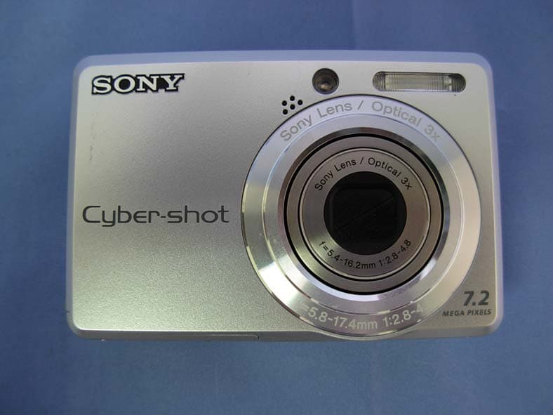
Click to zoom
Application Details
- Equipment Class
- JBP - Part 15 Class B Computing Device Peripheral
- Date of Grant
- Sep 09, 2007
- Application Purpose
- Original Equipment
- Date of Application
- Sep 09, 2007
- Equipment Note
- Digital Still Camera
- Country
- Taiwan
Documents & Files
Document Text
Text extracted from the exhibit documents filed with the FCC. Open a document above to read the original.
Users Manual
© 2007 Sony Corporation3-281-190-11(1) Digital Still Camera Cyber-shot Handbook DSC-S730 Before operating the unit, please read this Handbook thoroughly together with the “Instruction Manual” and the “Cyber-shot Step-up Guide”, and retain them for future reference. Table of contents Basic Operations Using the menu Using the Setup screen Viewing images on a TV Using your computer Printing still images Troubleshooting Others Index VCLICK! GB 2 Notes on using your camera Notes on the types of “Memory Stick” that you can use (not supplied) “Memory Stick Duo” You can use a “Memory Stick Duo” with the camera. “Memory Stick” You cannot use a “Memory Stick” with the camera. Other memory cards cannot be used. • For details on “Memory Stick Duo”, see page 95. When using a “Memory Stick Duo” with “Memory Stick” compatible equipment You can use the “Memory Stick Duo” by inserting it into the Memory Stick Duo Adaptor (not supplied). Memory Stick Duo Adaptor Notes on the LCD screen and lens • The LCD screen is manufactured using extremely high-precision technology so over 99.99% of the pixels are operational for effective use. However, some tiny black and/or bright dots (white, red, blue or green) may appear on the LCD screen. These dots are a normal result of the manufacturing process, and do not affect the recording. • Exposing the LCD screen or the lens to direct sunlight for long periods may cause malfunctions. Be careful when placing the camera near a window or outdoors. • Do not press against the LCD screen. The screen may be discolored and that may cause a malfunction. • Images may trail across on the LCD screen in a cold location. This is not a malfunction. • This camera is equipped with a power zoom lens. Be careful not to bump the lens, and be careful not to apply force to it. The images used in this Handbook The images used as examples in this Handbook are reproduced images, and are not actual images shot using the camera. Black, white, red, blue or green points 3 Table of contents Notes on using your camera .....................................................................2 Basic techniques for better images ...........................................................6 Focus – Focusing on a subject successfully..................................................... 6 Exposure – Adjusting the light intensity ............................................................ 8 Color – On the effects of lighting ....................................................................... 9 Quality – On “image quality” and “image size” ............................................... 10 Flash – On using the flash ............................................................................... 11 Identifying parts.......................................................................................12 Indicators on the screen ..........................................................................14 Changing the screen display ...................................................................18 Using the internal memory ......................................................................19 Using the mode dial.................................................................................20 Shooting images easily (Auto adjustment mode) ....................................21 Shooting still images (Scene selection)...................................................25 Viewing/deleting images..........................................................................28 Using menu items..............................................................................30 Menu items..........................................................................................31 Shooting menu ........................................................................................32 COLOR (Color Mode): Changing the vividness of the image or adding special effects (EV): Adjusting the light intensity 9 (Focus): Changing the focus method (Metering Mode): Selecting the metering mode WB (White Bal): Adjusting the color tones ISO: Selecting a luminous sensitivity Mode (REC Mode): Selecting the continuous shooting method (Flash Level): Adjusting the amount of flash light (Sharpness): Adjusting the sharpness of the image (Setup): Changing Setup items Basic Operations Using the menu 4 Table of contents Viewing menu ......................................................................................... 41 (Folder): Selecting the folder for viewing images - (Protect): Preventing accidental erasure DPOF: Adding a Print order mark (Print): Printing images using a printer (Slide): Playing back a series of images (Resize): Changing the image size of a recorded image (Rotate): Rotating a still image (Setup): Changing Setup items Trimming: Recording an enlarged image Using Setup items.............................................................................. 48 Camera .............................................................................................. 49 Internal Memory Tool ......................................................................... 51 Format Memory Stick Tool ............................................................................. 52 Setup 1............................................................................................... 55 Setup2................................................................................................ 56 Viewing images on a TV ......................................................................... 58 Using the Setup screen Viewing images on a TV Digital Zoom Function Guide Red Eye Reduction Auto Review Format Create REC. Folder Change REC. Folder Copy 1 LCD Backlight Beep Language Initialize 2 USB Connect Video Out Clock Set 5 Table of contents Enjoying your Windows computer ...........................................................60 Installing the software (supplied).............................................................62 On the “Picture Motion Browser” (…
Text truncated - open the document above for the full version.
Users Manual
36 Shooting menuFor details on the operation 1 page 30 Selects the metering mode that sets which part of the subject to measure to determine the exposure. • For details on the exposure, see page 8. • When using spot metering or center-weighted metering, setting [Focus] to [Center AF] is recommended to focus on the metering position (page 34). (Metering Mode): Selecting the metering mode Spot (Spot metering) () Measures only a part of the subject. • This function is useful when the subject is backlit or when there is strong contrast between the subject and the background. Center (Center-weighted metering) () Measures the center of the image, and determines the exposure based on the brightness of the subject there. Multi (Multi-pattern metering) Divides into multiple regions and measures each region. The camera determines a well-balanced exposure. Spot metering cross hairs Positions on the subject 37 Using the menu Shooting menuFor details on the operation 1 page 30 Adjusts the color tones according to the lighting condition in a situation, for example, when the colors of an image look strange. WB (White Bal): Adjusting the color tones Flash () Adjusts for the flash conditions. • You cannot select this item when shooting movies. Incandescent (n) Adjusts for places under an incandescent lamp, or under bright lighting, such as in a photo studio. Fluorescent () Adjusts for fluorescent lighting. Cloudy () Adjusts for a cloudy sky or shaded area. WB 38 Shooting menuFor details on the operation 1 page 30 • For details on the white balance, see page 9. • Under fluorescent lights that flicker, the white balance function may not work correctly even though you select [Fluorescent] (). • Except in [Flash] () modes, [WB] is set to [Auto] when the flash strobes. • Some options are not available depending on the Scene mode (page 27). Selects a luminous sensitivity with units of ISO. The larger the number, the higher the sensitivity. • For details on the ISO sensitivity, see page 8. • [ISO] is set to [Auto] in the Scene mode. Daylight () Adjusts for conditions outside under a clear sky, at sundown, night scenes, the presence of neon signs or fireworks. Auto Adjusts the White Balance automatically. ISO: Selecting a luminous sensitivity 1000 You can reduce image blurring in dark locations or moving subjects by increasing ISO sensitivity (select a larger number). However, images tend to become noisier as the ISO sensitivity number increases. Select an ISO sensitivity number according to shooting conditions. 800 400 200 100 Auto WB Large numberSmall number 39 Using the menu Shooting menuFor details on the operation 1 page 30 Selects whether the camera performs continuous shooting or not when you press the shutter button. On the [Burst] • When recording with the self timer, a series of a maximum of five images is recorded. • The recording interval is approximately XX seconds. • When the battery level is low, or when the internal memory or “Memory Stick Duo” does not sufficient space, you cannot shoot continuously. • You may not be able to shoot images in the Burst mode depending on the Scene mode (page 27). The maximum number of continuous shots (units: images) Mode (REC Mode): Selecting the continuous shooting method Burst () Records the maximum number of images in succession (refer to the following table) when you press and hold down the shutter button. • When “Recording” disappears, you can shoot the next image. • The flash is set to (Flash forced off). Normal Does not shoot continuously. SizeMaximum continuous shots 7Mxx 3:2xx 5Mxx 3Mxx VGAxx 16:9xx 40 Shooting menuFor details on the operation 1 page 30 Adjusts the amount of flash light. • To change flash mode, see page 22. • If the subject is too bright or dark, this adjustment may have no effect. Adjusts the sharpness of the image. See page 48. (Flash Level): Adjusting the amount of flash light + ( +) Toward +: Makes the flash level higher. Normal – ( –) Toward –: Makes the flash level lower. (Sharpness): Adjusting the sharpness of the image + () Toward +: Sharpens the image. Normal – () Toward –: Softens the image. (Setup): Changing Setup items Towa r d +Towa r d – 41 For details on the operation 1 page 30 Using the menu Viewing menu The default settings are marked with . Selects the folder containing the image you want to play back when using the camera with “Memory Stick Duo”. 1Select the desired folder with b/B on the control button. 2Select [OK] with v, then press z. zOn the folder The camera stores images in a specified folder of a “Memory Stick Duo”. You can change the folder or create a new one. • To create a new folder t [Create REC. Folder] (page 52) • To change the folder for recording images t [Change REC. Folder] (page 53) • When multiple folders are created in the “Memory Stick Duo” and the first or last image in the folder is displayed, the following indicators appear. : Moves to the previous folder. : Moves to the next folder. : Moves to either the previous or next folders. (Folder): Selecting the folder for viewing images OK See the following procedure. Cancel Cancels the selection. 42 Viewing menuFor details on the operation 1 page 30 Protects images against accidental erasure. The - indicator appears on a protected image. To protect images in single-image mode 1Display the image you want to protect. 2Press MENU to display the menu. 3Select [Protect] with b/B on the control button, then press z. The image is protected and the - (protect) indicator appears on the image. 4To protect other images, select the desired image with b/B, then press z. To protect images in index mode 1Press (Index) to display the index screen. 2Press MENU to display the menu. 3Select [Protect] with b/B on the control button, then press z. 4Select [Select] with v/V, then press z. 5Select the image you want to protect with v/V/b/B, then press z. A green - indicator appears on the selected image. 6Repeat step 5 to protect other images. 7Press MENU. 8Select [OK] wit…
Text truncated - open the document above for the full version.
External Photos
Report No: 078225R-ITUSP01V02 Page: 62 of 81 5. Attachment ¾ EUT Photograph (1) EUT Photo (2) EUT Photo Report No: 078225R-ITUSP01V02 Page: 63 of 81 (3) EUT Photo (4) EUT Photo Report No: 078225R-ITUSP01V02 Page: 64 of 81 (5) EUT Photo (6) EUT Photo Report No: 078225R-ITUSP01V02 Page: 65 of 81 (7) EUT Photo (8) EUT Photo Report No: 078225R-ITUSP01V02 Page: 66 of 81 (9) EUT Photo (10) EUT Photo Report No: 078225R-ITUSP01V02 Page: 67 of 81 (11) EUT Photo (12) EUT Photo
ID Label/Location Info
Hon Hai Precision Industry Co., Ltd. Nei-Hu Branch Office 1~11 F., No.32, Ji-hu Rd., Nei-hu, Taipei 114, Taiwan, R.O.C. FCC ID.: TVRDSCS730 FCC ID AND DoC Label
Internal Photos
Report No: 078225R-ITUSP01V02 Page: 68 of 81 (13) EUT Photo (14) EUT Photo Report No: 078225R-ITUSP01V02 Page: 69 of 81 (15) EUT Photo (16) EUT Photo Report No: 078225R-ITUSP01V02 Page: 70 of 81 (17) EUT Photo (18) EUT Photo Report No: 078225R-ITUSP01V02 Page: 71 of 81 (19) EUT Photo (20) EUT Photo Report No: 078225R-ITUSP01V02 Page: 72 of 81 (21) EUT Photo (22) EUT Photo Report No: 078225R-ITUSP01V02 Page: 73 of 81 (23) EUT Photo Report No: 078225R-ITUSP01V02 Page: 74 of 81 (24) EUT Photo Report No: 078225R-ITUSP01V02 Page: 75 of 81 (25) EUT Photo Report No: 078225R-ITUSP01V02 Page: 76 of 81 (26) EUT Photo (27) EUT Photo Report No: 078225R-ITUSP01V02 Page: 77 of 81 (28) EUT Photo Report No: 078225R-ITUSP01V02 Page: 78 of 81 (29) EUT Photo (30) EUT Photo Report No: 078225R-ITUSP01V02 Page: 79 of 81 (31) EUT Photo (32) EUT Photo Report No: 078225R-ITUSP01V02 Page: 80 of 81 (33) EUT Photo (34) EUT Photo Report No: 078225R-ITUSP01V02 Page: 81 of 81 (35) EUT Photo (36) EUT Photo
Operational Description
Report No: 078225R-ITUSP01V02 Page: 10 of 81 1.5. EUT Exercise Software Test Mode Mode 1: Slide show 1 Setup EUT and Monitor as shown on 1.4. 2 Play REC file (black loop). 3 Turn on the power. 4 Select play key. 5 Press MENU. 6 Press left key to select play OK. 7 Select START OK. 8 Show word of slide show on LCD display. 9 Test. Test Mode Mode 2: REC 1 Setup EUT and Monitor as shown on 1.4. 2 The lens of EUT was covered with black tape. 3 Turn on the power of all equipment. 4 Press REC key. 5 Save black file. Test Mode Mode 3: USB-LCD On 1 Setup EUT and PC as shown on 1.4. 2 Loop transmit REC file with USB cable. 3 Turn on the power. 4 Write DSC file to PC for example. Test Mode Mode 4: Preview 1 Setup EUT and Monitor as shown on 1.4. 2 The lens of EUT was covered with black tape. 3 Turn on the power of all equipment. 4 Select capture preview mode. 5 Test.
Test Report
Test Report Product Name : Digital Still Camera Model No. : DSC-S730 FCC ID : TVRDSCS730 Applicant : Hon Hai Precision Industry Co., Ltd. Nei-Hu Branch Office Address : 1~11 F., No.32, Ji-hu Rd., Nei-hu, Taipei 114, Taiwan, R.O.C. Date of Receipt : 2007/08/16 Issued Date : 2007/08/30 Report No. : 078225R-ITUSP01V02 The test results relate only to the samples tested. The test results shown in the test report are traceable to the national/international standard through the calibration of the equipment and evaluated measurement uncertainty herein. This report must not be used to claim product endorsement by CNLA, NVLAP, NIST or any agency of the Government. The test report shall not be reproduced except in full without the written approval of QuieTek Corporation. Report No: 078225R-ITUSP01V02 Page: 2 of 81 Test Report Certification Issued Date : 2007/08/30 Report No. : 078225R-ITUSP01V02 Product Name : Digital Still Camera Applicant : Hon Hai Precision Industry Co., Ltd. Nei-Hu Branch Office Address : 1~11 F., No.32, Ji-hu Rd., Nei-hu, Taipei 114, Taiwan, R.O.C. Manufacturer : Hon Hai Precision Industry Co., Ltd. Nei-Hu Branch Office Model No. : DSC-S730 Rated Voltage : AC 120 V / 60 Hz EUT Voltage : AC 120 V / 60 Hz Trade Name : SONY Applicable Standard : FCC CFR Title 47 Part 15 Subpart B: 2006 Class B, CISPR 22: 2006 Test Result : Complied Performed Location : Hsinchu EMC Laboratory N0. 75-2, 3rd Lin, Wangye Keng, Yonghxing Tsuen, Qionglin Shiang, Hsinchu County 307, Taiwan, R.O.C. TEL:+886-3-592-8858 / FAX:+886-3-592-8859 Documented By : ( Carol Tsai / Engineering Adm. Specialist ) Reviewed By : ( John Lee / Assistant Engineer ) Approved By : ( Arthur Liu / Deputy Manager ) Report No: 078225R-ITUSP01V02 Page: 3 of 81 Laboratory Information We , QuieTek Corporation, are an independent EMC and safety consultancy that was established the whole facility in our laboratories. The test facility has been accredited by the following accreditation Bodies in compliance with ISO 17025, EN 45001 and Guide 25: The related certificate for our laboratories about the test site and management system can be downloaded from QuieTek Corporation’s Web Site : http://tw.quietek.com/modules/myalbum/ The address and introduction of QuieTek Corporation’s laboratories can be founded in our Web site : http://www.quietek.com/ If you have any comments, Please don’t hesitate to contact us. Our contact information is as below: HsinChu Testing Laboratory : No.75-2, 3rd Lin, Wangye Keng, Yonghxing Tsuen, Qionglin Shiang, Hsinchu County 307, Taiwan, R.O.C. TEL:+886-3-592-8858 / FAX:+886-3-592-8859 E-Mail : [email protected] LinKou Testing Laboratory : No. 5, Ruei-Shu Valley, Ruei-Ping Tsuen, Lin-Kou Shiang, Taipei, Taiwan, R.O.C. TEL : 886-2-8601-3788 / FAX : 886-2-8601-3789 E-Mail : [email protected] Taiwan R.O.C. : BSMI, DGT, CNLA Germany : TUV Rheinland Norway : Nemko, DNV USA : FCC, NVLAP Japan : VCCI 0914 1313 Report No: 078225R-ITUSP01V02 Page: 4 of 81 TABLE OF CONTENTS Description Page 1. General Information ................................................................................................................. 5 1.1. EUT Description ............................................................................................................... 5 1.2. Mode of Operation ........................................................................................................... 6 1.3. Tested System Details......................................................................................................7 1.4. Configuration of Tested System ....................................................................................... 8 1.5. EUT Exercise Software .................................................................................................. 10 2. Technical Test......................................................................................................................... 11 2.1. Summary of Test Result ................................................................................................. 11 2.2. List of Test Equipment ....................................................................................................11 2.3. Measurement Uncertainty .............................................................................................. 12 2.4. Test Environment ........................................................................................................... 12 3. Conducted Emission .............................................................................................................. 13 3.1. Test Specification ........................................................................................................... 13 3.2. Test Setup ...................................................................................................................... 13 3.3. Limit................................................................................................................................ 13 3.4. Test Procedure ............................................................................................................... 14 3.5. Test Result ..................................................................................................................... 15 3.6. Test Photograph ............................................................................................................. 31 4. Radiated Emission ................................................................................................................. 35 4.1. Test Specification ........................................................................................................... 35 4.2. Test Setup ...................................................................................................................... 35 4.3. Limit................................................................................................................................ 36 4.4. Test Procedur…
Text truncated - open the document above for the full version.
Test Setup Photos
Report No: 078225R-ITUSP01V02 Page: 31 of 81 3.6. Test Photograph Test Mode : Mode 1: Slide show Description : Front View of Conducted Emission Test Setup Test Mode : Mode 1: Slide show Description : Back View of Conducted Emission Test Setup Report No: 078225R-ITUSP01V02 Page: 32 of 81 Test Mode : Mode 2: REC Description : Front View of Conducted Emission Test Setup Test Mode : Mode 2: REC Description : Back View of Conducted Emission Test Setup Report No: 078225R-ITUSP01V02 Page: 33 of 81 Test Mode : Mode 3: USB-LCD On Description : Front View of Conducted Emission Test Setup Test Mode : Mode 3: USB-LCD On Description : Back View of Conducted Emission Test Setup Report No: 078225R-ITUSP01V02 Page: 34 of 81 Test Mode : Mode 4: Preview Description : Front View of Conducted Emission Test Setup Test Mode : Mode 4: Preview Description : Back View of Conducted Emission Test Setup Report No: 078225R-ITUSP01V02 Page: 54 of 81 4.6. Test Photograph Test Mode : Mode 1: Slide show Description : Front View of Radiated Emission Test Setup Test Mode : Mode 1: Slide show Description : Back View of Radiated Emission Test Setup Report No: 078225R-ITUSP01V02 Page: 55 of 81 Test Mode : Mode 1: Slide show Description : Front View of Radiated Emission Test Setup (Horn) Test Mode : Mode 1: Slide show Description : Back View of Radiated Emission Test Setup (Horn) Report No: 078225R-ITUSP01V02 Page: 56 of 81 Test Mode : Mode 2: REC Description : Front View of Radiated Emission Test Setup Test Mode : Mode 2: REC Description : Back View of Radiated Emission Test Setup Report No: 078225R-ITUSP01V02 Page: 57 of 81 Test Mode : Mode 2: REC Description : Front View of Radiated Emission Test Setup (Horn) Test Mode : Mode 2: REC Description : Back View of Radiated Emission Test Setup (Horn) Report No: 078225R-ITUSP01V02 Page: 58 of 81 Test Mode : Mode 3: USB-LCD On Description : Front View of Radiated Emission Test Setup Test Mode : Mode 3: USB-LCD On Description : Back View of Radiated Emission Test Setup Report No: 078225R-ITUSP01V02 Page: 59 of 81 Test Mode : Mode 3: USB-LCD On Description : Front View of Radiated Emission Test Setup (Horn) Test Mode : Mode 3: USB-LCD On Description : Back View of Radiated Emission Test Setup (Horn) Report No: 078225R-ITUSP01V02 Page: 60 of 81 Test Mode : Mode 4: Preview Description : Front View of Radiated Emission Test Setup Test Mode : Mode 4: Preview Description : Back View of Radiated Emission Test Setup Report No: 078225R-ITUSP01V02 Page: 61 of 81 Test Mode : Mode 4: Preview Description : Front View of Radiated Emission Test Setup (Horn) Test Mode : Mode 4: Preview Description : Back View of Radiated Emission Test Setup (Horn)
Contact Information
Applicant
MING-SHENG WEI(Engineer)
Technical Contact
Quie Tek Corp.Emily Chen
[email protected]886-2-8792-6808
2 F No. 345 Xinhu 2nd Road Neihy District · Taipei · Taiwan
Test Firm
QuieTek CorporationKevin (Yu-Lung) Chen
Technical Specifications
| # | Rule Parts | Frequency Range | Power Output |
|---|---|---|---|
| 1 | 15B | - | - |
Other Applications from Hon Hai Precision Industry Co., Ltd. Nei-Hu Branch Office
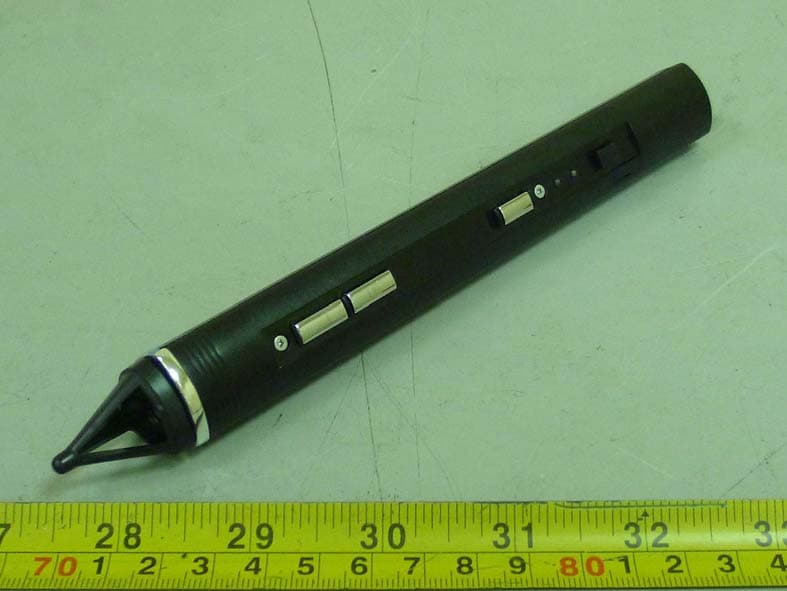
TVR-RC380P1
Oct 30, 2011Interactive pen
Equipment Class
DXX - Part 15 Low Power Communication Device Transmitter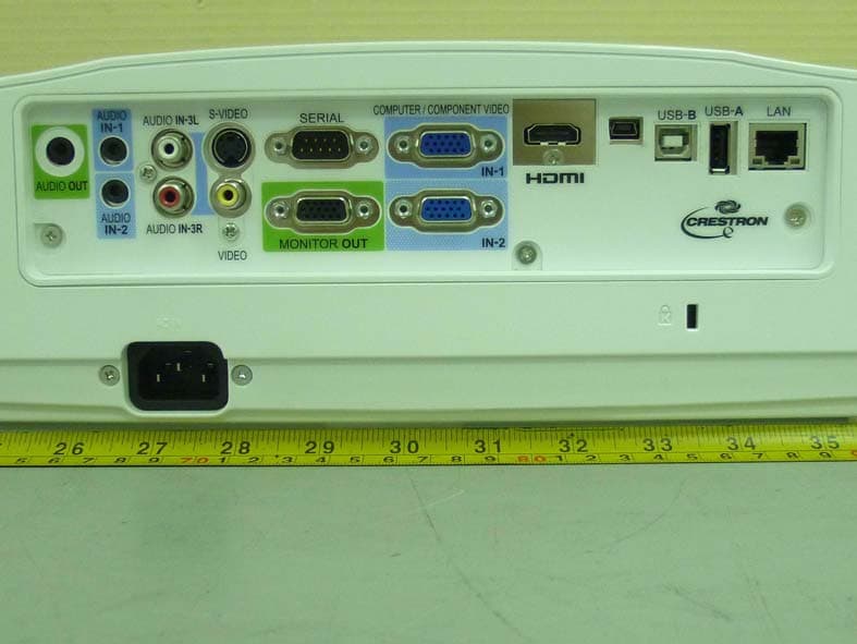
TVR-XD365UEST
Oct 30, 2011Data Projector
Equipment Class
DXX - Part 15 Low Power Communication Device Transmitter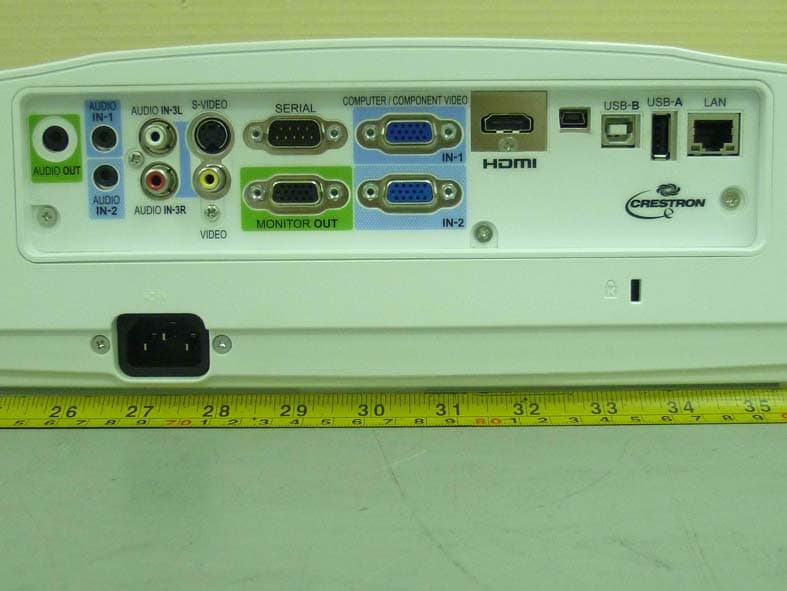
TVR-WD385UEST
Oct 27, 2011Data Projector
Equipment Class
DXX - Part 15 Low Power Communication Device Transmitter
TVRDSCS780
Dec 24, 2007Digital Still Camera
Equipment Class
JBP - Part 15 Class B Computing Device Peripheral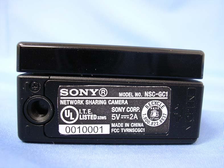
TVRNSCGC1
Jul 10, 2007Network Sharing Camera
Equipment Class
JBP - Part 15 Class B Computing Device Peripheral