TVV-PPAPPronto Intelligent Access Point
Pronto Networks, Inc
Click to zoom
Application Details
- Equipment Class
- DTS - Digital Transmission System
- Date of Grant
- Jul 07, 2014
- Application Purpose
- Original Equipment
- Date of Application
- Jul 07, 2014
- Equipment Note
- Pronto Intelligent Access Point
- Frequency Range
- 2412.00000000 - 2462.00000000
- Company
- Pronto Networks, Inc
- Country
- United States
Documents & Files
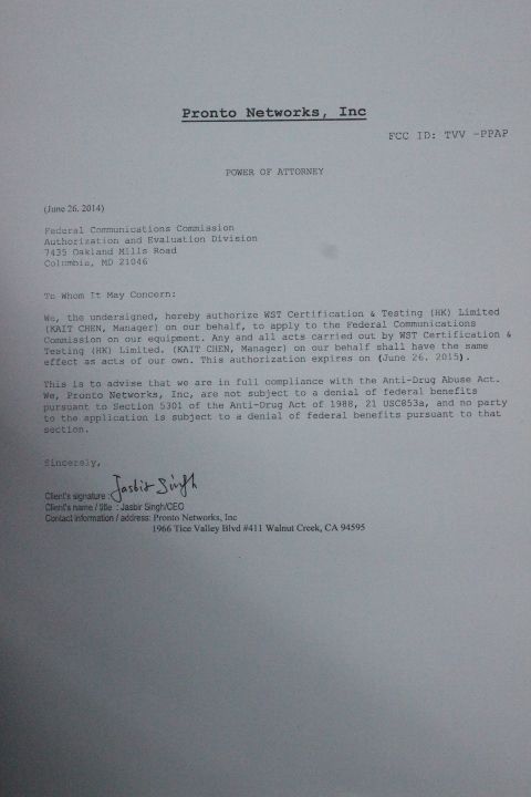
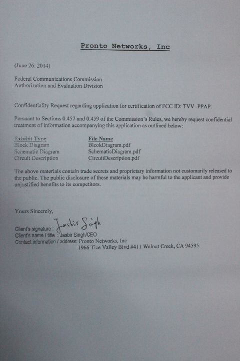
Document Text
Text extracted from the exhibit documents filed with the FCC. Open a document above to read the original.
Users Manual
Step 1: Package Contents Unbox and verify the following contents: • Pronto Point AP • Auxiliary tool for installation • Pronto Intelligence AP Quick Installation Guide • 1 RJ45 Ethernet Cable Step 2: Hardware Installation • Power on your computer • Connect one end of ethernet cable to POE switch port and the other end to Pronto Intelligent AP’s WAN port and power on the AP • Ensure that the Power LED is on (LED will glow in orange) • Ensure that the Wireless LED is on (LED will glow in blue) Pronto Intelligent Access Point Quick Start Guide Step 3: Access Point Configuration • Connect one end of the RJ45 Ethernet cable to the POE switch and other end to the Ethernet port of the computer • Ensure that the Network Connection is enabled on your computer • Assign an IP address within the range (192.168.0.2-254) e.g. 192.168.0.10 to your computer • Management IP for the AP is 192.168.0.1 • To configure the AP, open a web browser in your computer and type the following URL. http://192.168.0.1 • A login screen will appear. By default, the username of the AP is admin and password is pronto. You can set desired password after logging into the AP • Configure the AP, as you desire • By default the AP will broadcast unsecured ESSID as Pronto. The AP has provision to setup 4 ESSIDs and also to setup security for each one of them. Please refer the detailed User Manual at www.prontonetworks.com • Connect Internet back-haul to POE switch • Connect your computer to default Pronto ESSID and access Internet • Congratulations !! Your AP is configured successfully... Enjoy surfing Internet on Wi-Fi For queries call: +1 925 860 6200 or mail to [email protected] or visit www.prontonetworks.com 4. This device complies with Part 15 of the FCC Rules. Operation is subject to the following two conditions: (1) This device may not cause harmful interference, and (2) This device must accept any interference received, including interference that may cause undesired operation. Changes or modifications not expressly approved by the party responsible for compliance could void the user's authority to operate the equipment.
ID Label/Location Info
FCC LABLE: may cause undesired operation. FCC ID: TVV‐PPAP This device complies with Part 15 of the FCC Rules. Operation is subject to the following two conditions: (1) This device may not cause harmful interference, and (2) This device must accept any interference received, including interference that
ID Label/Location Info
Label Location: FCC ID: TVV‐PPAP This device complies with Part 15 of the FCC Rules. Operation is subject to the following two conditions: (1) This device may not cause harmful interference, and (2) This device must accept any interference received, including interference that
RF Exposure Info
FCC ID: TVV-PPAP Portable device According to §15.247(e)(i) and §1.1307(b)(1), systems operating under the provisions of this section shall be operated in a manner that ensures that the public is not exposed to radio frequency energy level in excess of the Commission’s guidelines. According to KDB 447498 (2)(a)(i) Frequency Range Maximum measured transmitter power 60/f SAR Limitation(mw) Low Frequency(MHZ) High Frequency(MHz) 2412 2462 2412 24.9 Maximum measured transmitter power Conducted Power(mw) Max Antenna Gain(dBi) EIRP(mw) 2412 0 12.45 Remark: The best case gain of the antenna is 0dBi. 0dBi logarithmic terms convert to numeric result is nearly 1 According to the formula. calculate the EIRP test result: EIRP= P x G = 12.45x 1 = 12.45 Threshold at which no SAR required is 24.9mw. Maximum Tx power is 12.45EIRP. Conclusion: No SAR is required. SIMULTANEOUS TRANSMISSION EVALUATION N/A
Test Report
Report No.: CTL20140622006 WST Certification & Testing (HK) Limited Page 1 of 59 FCC TEST REPORT For Pronto Networks, Inc Pronto Intelligent Access Point Trade Name : Pronto Model No. : PPAP-11n-S-48C, PPAP-11n-S-24C FCC ID : TVV-PPAP Frequency range : 2412-2462MHz Number of Channel : 11CH Type of antenna : Internal monopole Antenna Applicant : Pronto Networks, Inc 1966 Tice Valley Blvd #411 Walnut Creek, CA 94595 Regulation : FCC Rules and Regulations Part 15 Subpart C Section 15.247 Prepared by : WST Certification & Testing (HK) Limited Address : 12/F., San Toi Building,137-139 Connaught Road Central, Hong Kong, China Report No.: : WST20140622006 Test Date : June 22-26, 2014 Date of Report : June 26, 2014 Report No.: CTL20140622006 WST Certification & Testing (HK) Limited Page 2 of 59 TABLE OF CONTENT Description Page Test Report Declaration 1. TEST PROCEDURES AND RESULTS ............................................................................... 4 2. GENERAL INFORMATION ................................................................................................ 5 1.1. General Information ............................................................................................................................ 5 1.2. Test Facility ........................................................................................................................................ 6 3. TEST INSTRUMENT USED ................................................................................................. 7 4. OPERATION OF EUT DURING TESTING ........................................................................... 9 5. 6DB BANDWIDTH MEASUREMENT ................................................................................ 10 5.1. Block Diagram of Test Setup ...................................................................................................... 10 5.2. Limits .......................................................................................................................................... 10 5.3. Test Procedure .......................................................................................................................... 10 5.4. Test Result ................................................................................................................................. 10 6. MAXIMUM PEAK OUTPUT POWER ................................................................................. 16 6.1. Block Diagram of Test Setup ...................................................................................................... 16 6.2. Limits........................................................................................................................................... 16 6.3. Test Procedure ............................................................................................................................. 16 6.4. Test Result ................................................................................................................................... 16 7. POWER SPECTRAL DENSITY MEASUREMENT ............................................................ 20 7.1. Block Diagram of Test Setup ...................................................................................................... 20 7.2. Limits........................................................................................................................................... 20 7.3. Test Procedure ............................................................................................................................. 20 7.4. Test Result ................................................................................................................................... 20 8. BAND EDGE COMPLIANCE TEST .................................................................................... 26 8.1. Block Diagram of Test Setup ...................................................................................................... 26 8.2. Limits........................................................................................................................................... 26 8.3. Test Procedure ............................................................................................................................. 26 8.4. Test Result ................................................................................................................................. 27 9. RADIATED SPURIOUS EMISSION TEST .......................................................................... 37 9.1. Block Diagram of Test Setup ...................................................................................................... 37 9.2. Limits........................................................................................................................................... 38 9.3. Restricted bands of operation ...................................................................................................... 38 9.4. Test Procedure .......................................................................................................................... 39 9.5. Test Result ................................................................................................................................... 40 10. CONDUCTED SPURIOUS EMISSION COMPLIANCE TEST ........................................... 49 10.1. Block Diagram of Test Setup ...................................................................................................... 49 10.2. Limits........................................................................................................................................... 49 10.3. Test Procedure ............................................................................................................................. 49 10.4. Test Result ................................................................................................................................... 49 11. AC PO…
Text truncated - open the document above for the full version.
Test Setup Photos
PHOTOGRAPH OF TEST Radiated Emission AC power line conducted emission
Contact Information
Applicant
Jasbir Singh(CEO)
Test Firm
Shenzhen CTL Testing Technology Co., Ltd.Tracy Qi
[email protected]86-755-89486194
Technical Specifications
| # | Rule Parts | Frequency Range | Power Output |
|---|---|---|---|
| 1 | 15C | 2.41 GHz - 2.46 GHz | 12.45 mW |
Other Applications from Pronto Networks, Inc
TVV-PIAP
Oct 05, 2015Pronto Intelligent Access Point
Equipment Class
NII - Unlicensed National Information Infrastructure TX
TVV-PN-PPSC-A-10
Dec 07, 2009Pronto Point Service Controller
Equipment Class
DTS - Digital Transmission System
TVV-PN-CPP-A-1422
Jan 16, 2006802.11 b/g Wireless Router
Equipment Class
DTS - Digital Transmission System