TW5GD71044 CH Digital Wireless Security System (Monitor)
Shenzhen Gospell Smarthome Electronic Co., Ltd.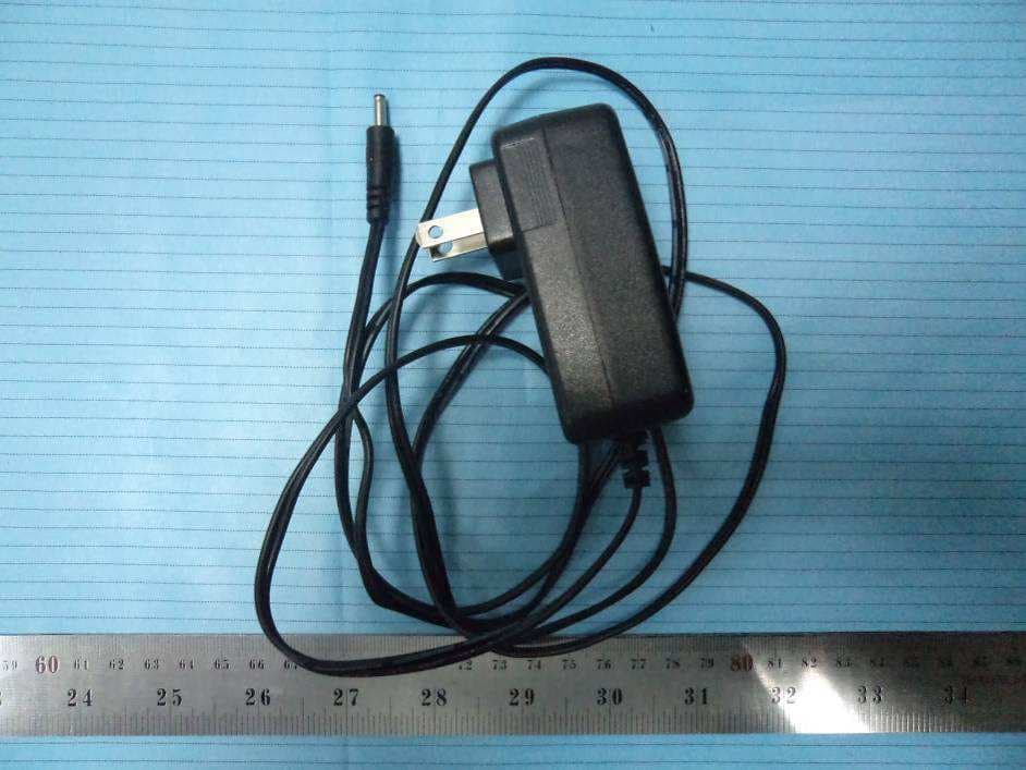
Click to zoom
Application Details
- Equipment Class
- DSS - Part 15 Spread Spectrum Transmitter
- Date of Grant
- Sep 27, 2012
- Application Purpose
- Original Equipment
- Date of Application
- Sep 27, 2012
- Equipment Note
- 4 CH Digital Wireless Security System (Monitor)
- Frequency Range
- 2403.00000000 - 2478.00000000
- Country
- China
Documents & Files
Document Text
Text extracted from the exhibit documents filed with the FCC. Open a document above to read the original.
Users Manual
01 02 CONTENTS ①Camera x 4 ② 7"TFT LCD Monitor x 1 ③ ④ Adapter x 5 ⑤ SD Card(optional) x 1 ⑥ AV Output Cable x 1 ⑦ Bracket for Monitor (optional)x 1 ⑧ (optional)x 1Remote control Packing List Welcome This product is a household monitoring recording device. It consists of four cameras installed at entrances/exits of the home and one DVR receiver with a 7-inch LCD monitor. The four-split screen of the receiver can display the monitoring pictures of four accessed cameras. In addition, the infrared sensing alarm function of human body is available. Thus, a household closed monitoring system is presented. * The pictures are for reference only, please refer to real subjects. For 8105JM, the camera has IR-cut function and image effect is better than 8104JM. Bracket for Camera x 1 ⑦ ⑧ ① ③② ⑤⑥ ④ Features ● 4CH digital wireless camera & DVR system; ● Simple installation- no cables required; ● Total digital wireless, no interferences, no privacy leak; ● 7” LCD monitor with integrated video recorder; ● Support up to 32GB SD card or external mobile disk by USB2.0 (up to 1TBmobile disk); ● Support 4 cameras/ 24hours /7days non-stop overwrite recording; ● Multiple recording modes: manual,schedule, and motion activated; ● 5m night vision range; ● Video quality: 4CH VGA 10fps, 1CH VGA 30fps; ● Weather proof outdoor cameras with 300m/1000ft transmission open range; ● Video output function for bigger monitor. ● IR-cut function. (only for 8105JM) ! Please know that this monitor is not a PC, so some of the memory devices may not work on this monitor. Welcome Features Packing List Structure Installation Operations ● Basic operations ● Video recording ● Playback ● Delete Video ● Video Output System setting ● Date / time ● Language ● Record Mode ● Format SD/USB ● Storage for Recording ● Display Items ● TV System ● System Information ● Scan Mode Period ● Mute ● Load Default ● Brightness ● Volume Record ● Timer Recording ● PIR Recording Playback Camera ● Pairing ● Active ● PIP Setting Alarm setting Specifications FAQ FCC Information Warnings 02 02 02 03 04 05 05 07 08 09 09 10 11 11 11 12 12 12 13 13 13 14 14 14 14 15 15 15 16 16 16 18 18 19 21 20 21 21 ● System Update 13 Troubleshooting 22 Structure 03 04 Installation 1. Install the camera at the proper monitoring location. The camera can be installed in two modes: 3. Insert the SD card or connect an external storage device, such as a mobile hard disk. Note: It doesn’t support hot plugging of SD card or external storage device. Antenna 7"TFT-LCD Power on/off OK Button Navigate Button Delete file/LCD、TV Switch Menu Record/stop Video Playback Video Quarter Display Button Display Mode Microphone Bracket USB Port SD Card Slot AV Output Power Port Link Indicator Power Indicator Antenna Power Input Infrared LEDs Lens Bracket Antenna Socket Link Indicator Power Indicator Pair Button Microphone ① Upright installation: Install the camera on a level plane. ② Reverse installation: Install the camera in the celilng. 2. Install the receiver at a proper location. This receiver is provided with two kinds of brackets, so it can be installed in two modes: ① Positioned on a level plane② Mounted to the wall Use screws to fix the bracket to the wall. Clamp the receiver on the bracket PIR infrared sensor Operations 05 06 ● Basic operations 1. Connect the camera to the power supply. The power Indicator on the back is turned on: 3. Press the power switch on the receiver for 2s. or press the power switch on the remote control(direct the remote control toward the receiver). The power indicator is turned on and the power-on picture appears. 4. Pair the cameras and receiver respectively (at most four cameras can be connected at the same time). Pairing is completed by default before delivery. If pairing is not completed, complete pairing according to “Pairing” on page 16. 2. Connect the receiver to the power supply. 6. Press the button to switch between four display modes: V 2011/11/05/09:30 V 2011/11/05/09:30 C2 C3 C4 2011/11/05/09:30 2011/11/05/09:30 2011/11/05/09:30 V 2011/11/05/09:30 C2 C3 C4 2011/11/05/09:30 2011/11/05/09:30 2011/11/05/09:30 图像显示区域 图像显示区域 图像显示区域 Four picturesOne picture One large picture and three small pictures One large picture and three small picture 7. Press the button to enter cyclic mode display. Five cyclic intervals are available: 5s, 10s, 15s, 20s, and 30s and can be set under “System”. Meanings of icons on the real-time monitoring picture: Mobile hard disk inserted successfully SD card inserted successfully Camera name Signal intensity Recording status Current camera C2 C3 C4 V 2011/11/05/09:30 2011/11/05/09:30 2011/11/05/09:302011/11/05/09:30 5. After successful pairing, the following real-time monitoring picture appears: V 2011/11/05/09:30 C2 C3 C4 2011/11/05/09:30 2011/11/05/09:30 2011/11/05/09:30 Picture display area Time stamp Picture display area Picture display area Picture display area Picture display areaPicture display area Picture display areaPicture display area Picture display area Picture display area Picture display area Picture display area Picture display area Picture display area 07 08 Manual Recording: 1. In the real-time monitoring status, press the and buttons to select the camera for video recording as the current camera. 2. Press the recording/stopping button on the device. The recording icon is displayed on the screen, indicating that recording starts. 3. Press the button on the device again to stop recording. Timer Recording: Set the recording start/stop time through the “Timer Recording” menu. The device automatically records according to the set start/stop time. After recording, it automatically saves the video. Specific steps are as follows: 1. Press the MENU button to enter setting interface; 2. Press the or button to select “Record” and press the OK button to enter; 3. Press the or button to select “Timer Recording” and press the OK button to enter; 4. Press the or button to select “New Schedule” and press the OK button to enter…
Text truncated - open the document above for the full version.
Cover Letter(s)
ShenZhen GOSPELL Smarthome Electronic CO.,LTD 5Floor/Block 2, Vision (SZ) Park, Hi-Tech Industrial Park,Shenzhen,China Tel:+86 755-29980909-8090 Fax:+86 755-27478338 FCC Authorization 9/24/2012 FEDERAL COMMUNICATIONS COMMISSIONS Authorization and Evaluation Division 7435 Oakland Mills Road Columbia, MD 21046 Subject: Agent Authorization To whom it may concern: We ShenZhen GOSPELL Smarthome Electronic CO.,LTD , the undersigned, Hereby authorizes Bay Area Compliance Laboratories Corporation to act on its behalf in all matters relating to application for Equipment authorization, including the signing of all documents relating to these matters. All acts carried out by Bay Area Compliance Laboratories Corp. our behalf shall have the same effect as our own action. We, the undersigned, hereby certify that we are not subject to a denial of federal benefits, that includes FCC benefits, pursuant to Section 5301 of the Anti-Drug Abuse Act of 1988, 21 U.S.C. 853(a). This authorization is valid until further written notice from the applicant. Sincerely Yours, Evan Qi Manager
Cover Letter(s)
ShenZhen GOSPELL Smarthome Electronic CO.,LTD 5Floor/Block 2, Vision (SZ) Park, Hi-Tech Industrial Park,Shenzhen,China Tel:+86 755-29980909-8090 Fax: +86755 - 27478338 FCC Confidential Authorization 9/24/2012 FEDERAL COMMUNICATIONS COMMISSIONS Authorization and Evaluation Division 7435 Oakland Mills Road Columbia, MD 21046 Confidentiality Request regarding application for certification of FCC ID: TW5GD7104 Pursuant to Sections 0.457 and 0.459 of the Commission’s Rules, we hereby request confidential treatment of information accompanying this application as outlined below: Detailed Circuit Schematics of EUT--- (Long term) Block Diagram --- (Long term) Circuit Description --- (Long term) The above materials contain trade secrets and proprietary information not customarily released to the public. The public disclosure of these materials may be harmful to the applicant and provide unjustified benefits to its competitors. The applicant understands that pursuant to Section 0.457 of the Rules, disclosure of this application and all accompanying documentation will not be made before the date of the Grant for this application. Sincerely Yours, Evan Qi Manager
External Photos
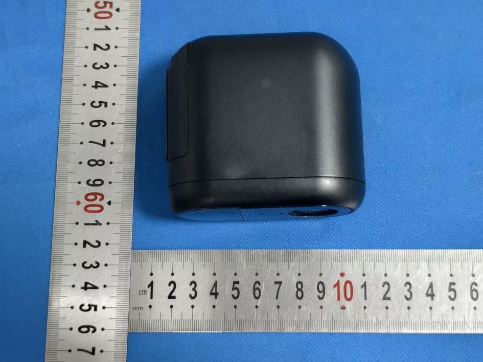
EXHIBIT B - EUT EXTERNAL PHOTOGRAPHS EUT – Front View EUT – Rear View Antenna EUT – Top View EUT – Bottom View EUT – Left Side View EUT – Right Side View EUT – Antenna View EUT – Antenna Port View EUT – Adapter View EUT – Adapter Label View
ID Label/Location Info
EXHIBIT A - FCC ID LABELING AND LOCATION FCC ID Label FCC ID Label Location The label shown shall be permanently affixed at a conspicuous location on the device and be readily visible to the user at the time purchase (Labeling requirements per 2.925) Label here
Internal Photos
EXHIBIT C - EUT INTERNAL PHOTOGRAPHS EUT – Cover off View EUT – Main Board Top View EUT – Main Board Top Shielding off View EUT – Main Board Bottom View EUT – Key Board Top View EUT – Key Board Bottom View
RF Exposure Info
Bay Area Compliance Laboratories Corp. (Shenzhen) Report No.: RSZ120823002-00 FCC Part15.247 Page 8 of 35 FCC §15.247 (i) & §2.1091 - MAXIMUM PERMISSIBLE EXPOSURE (MPE) Standard Applicable According to subpart 15.247 (i) and subpart 1.1307 (b)(1), 2.1091 systems operating under the provisions of this section shall be operated in a manner that ensures the public is not exposed to RF energy level in excess of the communication guidelines. Limits for General Population/Uncontrolled Exposure Limits for General Population/Uncontrolled Exposure Frequency Range (MHz) Electric Field Strength (V/m) Magnetic Field Strength (A/m) Power Density (mw/cm 2 ) Averaging Time (Minutes) 0.3-1.34 614 1.63 *(100) 30 1.34-30 824/f 2.19/f *(180/f 2 ) 30 30-300 27.5 0.073 0.2 30 300-1500 / / f/1500 30 1500-100,000 / / 1.0 30 f = frequency in MHz * = Plane-wave equivalent power density MPE Calculation Predication of MPE limit at a given distance S = PG/4πR² Where: S = power density (in appropriate units, e.g. mW/cm 2 ) P = power input to the antenna (in appropriate units, e.g., mW). G = power gain of the antenna in the direction of interest relative to an isotropic radiator, the power gain factor, is normally numeric gain. R = distance to the center of radiation of the antenna (appropriate units, e.g., cm) Antenna Gain Conducted Power Frequency (MHz) (dBi) (numeric)(dBm) (mW) Evaluation Distance (cm) Power Density (mW/cm 2 ) MPE Limit (mW/cm 2 ) 2478 2 1.58 17.11 51.40 20 0.016 1.0 Result: The EUT meets FCC MPE limit at 20 cm distance.
Test Report
Note: This test report is prepared for the customer shown above and for the equipment described herein. It may not be duplicated or used in part without prior written consent from Bay Area Compliance Laboratories Corp. This report must not be used by the customer to claim product certification, approval, or endorsement by NVLAP*, or any agency of the Federal Government. * This report may contain data that are not covered by the NVLAP accreditation and shall be marked with an asterisk “★” FCC PART 15.247 TEST REPORT For Shenzhen Gospell Smarthome Electronic Co., Ltd. 5 Floor/Block 2, Vision (SZ) Park, Hi-Tech Industrial Park, Shenzhen, Guangdong, China FCC ID: TW5GD7104 Report Type: Original Report Product Type: 4 CH Digital Wireless Security System (Monitor) Test Engineer: Gardon Zhang Report Number: RSZ120823002-00 Report Date: 2012-09-25 Reviewed By: Alvin Huang RF Leader Test Laboratory: Bay Area Compliance Laboratories Corp. (Shenzhen) 6/F, the 3rd Phase of WanLi Industrial Building ShiHua Road, FuTian Free Trade Zone Shenzhen, Guangdong, China Tel: +86-755-33320018 Fax: +86-755-33320008 www.baclcorp.com.cn Bay Area Compliance Laboratories Corp. (Shenzhen) Report No.: RSZ120823002-00 FCC Part15.247 Page 2 of 35 TABLE OF CONTENTS GENERAL INFORMATION.......................................................................................................................................4 PRODUCT DESCRIPTION FOR EQUIPMENT UNDER TEST (EUT) .....................................................................................4 OBJECTIVE...................................................................................................................................................................4 RELATED SUBMITTAL(S)/GRANT(S).............................................................................................................................4 TEST METHODOLOGY..................................................................................................................................................4 TEST FACILITY.............................................................................................................................................................4 SYSTEM TEST CONFIGURATION ..........................................................................................................................6 DESCRIPTION OF TEST CONFIGURATION......................................................................................................................6 EUT EXERCISE SOFTWARE..........................................................................................................................................6 EQUIPMENT MODIFICATIONS.......................................................................................................................................6 BLOCK DIAGRAM OF TEST SETUP................................................................................................................................6 SUMMARY OF TEST RESULTS ...............................................................................................................................7 FCC §15.247 (i) & §2.1091 - MAXIMUM PERMISSIBLE EXPOSURE (MPE).........................................................8 STANDARD APPLICABLE..............................................................................................................................................8 FCC §15.203 – ANTENNA REQUIREMENT ............................................................................................................9 APPLICABLE STANDARD..............................................................................................................................................9 ANTENNA CONNECTOR CONSTRUCTION......................................................................................................................9 FCC §15.207 (a) – AC LINE CONDUCTED EMISSIONS .....................................................................................10 APPLICABLE STANDARD............................................................................................................................................10 MEASUREMENT UNCERTAINTY..................................................................................................................................10 EUT SETUP................................................................................................................................................................10 EMI TEST RECEIVER SETUP.......................................................................................................................................11 TEST PROCEDURE......................................................................................................................................................11 TEST EQUIPMENT LIST AND DETAILS.........................................................................................................................11 TEST RESULTS SUMMARY..........................................................................................................................................11 TEST DATA................................................................................................................................................................11 FCC §15.209, §15.205 & §15.247(d) - SPURIOUS EMISSIONS.............................................................................14 APPLICABLE STANDARD............................................................................................................................................14 MEASUREMENT UNCERTAINTY..................................................................................................................................14 EUT SETUP................................................................................................................................................................14 EMI TEST RECEIVER & SPECTRUM ANALYZER SETUP.....…
Text truncated - open the document above for the full version.
Test Setup Photos
EXHIBIT D - TEST SETUP PHOTOGRAPHS Conduction Emissions - Front View Conduction Emissions - Side View Radiated Emissions View - Below 1 GHz Radiated Emissions View - Above 1 GHz
Contact Information
Applicant
Richie Xiao(Certified Engineer)
Test Firm
Bay Area Compliance Laboratory Corp. (Shenzhen)John Chan
Technical Specifications
| # | Rule Parts | Frequency Range | Power Output |
|---|---|---|---|
| 1 | 15C | 2.40 GHz - 2.48 GHz | 51.40 mW |
Other Applications from Shenzhen Gospell Smarthome Electronic Co., Ltd.
TW5T5200JDA
Jun 17, 2026Wireless Smart Battery Camera
Equipment Class
DTS - Digital Transmission System
TW5GD8217B
Jul 04, 20222.4GHz Digital Wireless Baby Monitor
Equipment Class
DXX - Part 15 Low Power Communication Device Transmitter
TW5GD7606
Jul 04, 20222.4GHz Digital Wireless Baby Monitor
Equipment Class
DXX - Part 15 Low Power Communication Device Transmitter
TW5T5703HCT
Jan 07, 2021HD WiFi Camera
Equipment Class
DTS - Digital Transmission System
TW5GD8205
Sep 06, 20202.4GHz Digital Wireless Baby Monitor
Equipment Class
DSS - Part 15 Spread Spectrum Transmitter