TW5GD8723WIFI REARVIEW CAMERA
Shenzhen Gospell Smarthome Electronic Co., Ltd.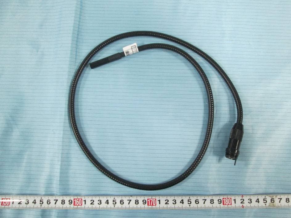
Click to zoom
Application Details
- Equipment Class
- DTS - Digital Transmission System
- Date of Grant
- Sep 15, 2014
- Application Purpose
- Original Equipment
- Date of Application
- Sep 15, 2014
- Equipment Note
- WIFI REARVIEW CAMERA
- Frequency Range
- 2422.00000000 - 2452.00000000
- Country
- China
Documents & Files
Document Text
Text extracted from the exhibit documents filed with the FCC. Open a document above to read the original.
Users Manual
Version 1.0 Please read this user manual carefully before using this product. Failure to understand operation procedures may result in injury. Model: GD8723 EU Environmental Protection Waste electrical products should not be disposed of with household waste. Please recycle where facilities exist. Check with your local authority or retailer for recycling advice. WiFi Inspection Camera Model: GD8723 INSPECTION TOOL INSPECTION TOOL CONTENTS 02 01 ※ Prevent object and liquid entry. Never spill liquid of any kind on the video display unit. Liquid increases the risk of electrical shock and damage to the product. ※ The unit is not shock-resistant. Do not use Explorer Standard as a hammer and avoid high impact resultant from things such as dropping the unit from height ※ Do not immerse camera handle in water. Avoid moisture, and store product in a dry place. Such measures reduce the risk of electric shock and damage. The lens and the tube are water when the unit is fully assembled, but the handle is not.resistant ※ Do not use the camera if condensation forms inside the lens. Let the water evaporate before using again. ※ Turn off the system if it is not in use. ※ This product can only be completely disconnected for from its power source by unplugging the power adapter. ※ Attention should be given to the environmental aspects of battery disposal. ※ Remove the batteries when cleaning the unit. ※ Remove the batteries before storing the unit for a long time. ※ When necessary, REPLACE ALL FOUR (4) BATTERIES in this unit with new ones, not one (1) or two (2) batteries at a time. ※ Use only the size and type of battery specified. ※ Be sure to install the battery with the correct polarity as indicated in the battery compartment. ※ Properly dispose of batteries. Exposure to high temperatures can cause batteries to explode, so do not dispose of in a fire. Place tape over the terminals to prevent direct contact with other objects. ※ Some countries have regulations concerning battery disposal. Please follow all applicable regulations. WARNING! Read and understand all instructions. Failure to follow all instructions listed below may result in electric shock, fire and/or serious personal injury. Installation 04 General Safety Information 02 Welcome 03 Features 03 Packing List 03 Structure 04 Operation 06 Basic Operation 06 08 Specifications FCC Information 07 07 Operations for iOS Apple system client Installation APP software WiFi Connection Device Operation Important Notes Operations for Android system client Installation APP software WiFi Connection Device Operation Important Notes * GD8723 = GT8723(handle) + GT4853(camera) SAVE THESE INSTRUCTIONS! GENERAL SAFETY INFORMATION 09 14 14 14 15 18 20 21 11 04 03 Congratulations on your purchase of WiFi inspection camera. Please read the user manual carefully before using this product. This product is designed as a remote inspection device with WiFi transmission (support iPhone, iPad and Android phone), capable of recording video/taking pictures. Appropriate for use in surveying pipes or other hard-to-reach places, equipment or furnishing installation, car repair, etc. Features include waterproof LED lens, real-time recording. ● ● Allows for easy surveying of small, hard-to-reach places ● Mini 17/9/5.8/5.5/4.5mm water-proof camera with 1m (3 ft.) flexible extended tube ● Manufactured and tested to IP67 waterproof standard ● Video recording and photo capture capability ● Increase visibility with 3×zoom capability ● Adjustable brightness on lens-mounted LED light ● 3 useful accessories included: Hook, mirror and magnet ● Lightweight, hand-held design, flexible and convenient to use WIFI transmission, support iPhone, iPad and Android phone Flexible Tube with Lens x 1 Handle x 1 Accessories (only for GD8723) x 1 Power Indicator Power Switch Flexible Tube Mini Waterproof LED Lens Battery Slot Flexible Tube Interface To Install Batteries (Dry your hands before installation or replacing batteries.) 1. Remove the cover as illustrated below: 2. Remove battery compartment and insert four (4) AA batteries into their appropriate slots, with proper orientation, as indicated on the battery compartment. 3. Reinstall battery compartment and replace battery cover and screw Reset Take a photo Rotate button 9mm Camera for GD8723 FEATURES STRUCTURE WELCOME PACKING LIST Installation 06 05 To Attach Flexible Tube with Handle To connect the flexible tube camera with control handle, first make sure that the keyed end of the tube is aligned with the slot in the handle, then use slight force to push them together. Once properly aligned, twist the treaded knob clockwise until the connection is securely in place. Fasten the treaded knob Keyed end plugs into socket To Install Accessories The three (3) included accessories (mirror, hook and magnet) are all attached to the camera in the same way as illustrated below: to prepare accessory for installation, push down on stem-side of black interface while pulling away from adjacent side. This will open the base of the accessory. Next, align inside of stem-side to either treaded surface at the base of camera head. Tighten to secure the accessory in place. Wear the rubber ring Hook the hole GD8723 Twin LEDs provide lighting 1. As you roll the power switch to turn on the camera, the power indicator on the camera handle will light. The rolling switch then acts as a dimmer for the twin LEDs that surround the camera on the end of the flexible tube. 2. When in use, the tube should easily maneuver itself into position. Do not apply excessive force. The flexible tube can be bent into numerous shapes that may help you explore areas you otherwise thought were impossible to see. 3. The accessories included with WiFi inspection camera can be used to retrieve small items like dropped rings or screws. Basic Operation 1 4. Note: Please use coins except for sharp objects to operate, so as not to damage the knob. The connecting part of the handle can be rotated, th…
Text truncated - open the document above for the full version.
Users Manual
14 13 4. Touch “Forget” to remove network records. Then, reconnect to the network using the previous WiFi connection methods. Operations for Android system client Touch “Settings” on the home screen of your device. Ulife tools ULIFE TEAM / Media and video (2) OPEN To install software for your smart mobile device that runs an Android system: 1. Turn on interlligent mobile device and enter Google Play store. Search for the software “Ulife tools”, and download. 2. Touch Install. The software can be installed on your device. 3. After the installation is complete, the icon of the software is displayed on the home screen, as shown in the following figure. Installation APP software WiFi Connection Touch “WLAN” and select your camera (The initial SSID is “ ”) and connect the WiFi with default password (). WIFICAMERA 88888888 Note handle to select WIFI channels. then reconnect the WIFI. : When the WIFI connection problem, the user can turn on / off the power switch of 16 15 Device Operation Note: If the WiFi interruption occurs when you view an image, or the picture viewing stops. In this case, exit the application and check whether the WiFi connection is proper. Open the APP, if the wifi connection is successful, the video could be seen in the APP as shown below. Settings Touch this icon to display the settings menu. You can set a new SSID or password for your WiFi network. Change the WiFi channel. Take a photo Record a video 18 17 1.Touch “Settings” on the home screen of your device. After you change the SSID or password, touch Settings on the home screen to forget this network and reconnect your device to the network. Otherwise, a message indicating a login error is always displayed. To forget this network: Important Notes: Touch the "Browsing files" in can view the picture or video.Enter the pictures can choose to send the file. the settings and 2.Touch to search for the WiFi name. 3.Then touch the modified WiFi camera. WLAN 20 19 4.Touch “Forget” to remove network records. Then, reconnect to the network using the previous WiFi connection methods. Note the batteries must be replaced. If you forget the SSID and password of the smart mobile device, you can press Reset on the product for 5 seconds to enable factory defaults. : Normally the yellow light is on. When the red light is on, the battery voltage is low and * Actual transmission range of wireless monitoring may vary according to the weather, location, interference or building construction. * All specifications are subject to minor change without prior notice. < 400mA 260 x 50 x 40 (mm) (Excluding Flexible Tube) 174g 20~85%RH -20~55/14F~122F OOOO CC camera >1 hours Minimum Illumination Horizontal Viewing Angle Consumption Current (Max.) Handle Weight Imaging Sensor Effective Pixels Power Supply Operating Temperature Operating Humidity (Max.) Waterproof Capacity Transmission Frequency Model No. Tube Diameter Working Time AA x (1.5V x 4)4 batteries CMOS 2400~2483.5MHz IP67 (for lens/tube only) Transmit Power <14dBm Receiver Sensitivity11b:-90,11g/n:-72 dBm Transmission Rate 1--150M bps Frequency Stability ±20 PPm Unobstructed Effective Range ≥10 m Working Voltage DC 4V--6.5V NTSC PAL 0 Lux (LED ON) GD8723 Specifications Dimensions (W D H)x x Modulation / Demodulation Mode 802.11g/n:OFDM (BPSK, QPSK, 16QAM, 64QAM) 802.11b:DSSS (CCK, DQPSK, DBPSK) 45 o 9mm 640 x 480 640 480x Picture/Video Pixels640480 x Frame Rate20 frame/second This device complies with part 15 of the FCC Rules. Operation is subject to the following two conditions: (1) This device may not cause harmful interference; (2) This device must accept any interference received, including interference that may cause undesired operation. Changes or modifications not expressly approved by the party responsible for compliance could void the user’s authority to operate the equipment. The graphics included in this user manual are subject to minor change without notice. FCC information 21 uncontrolled environment . FCC Radiation Exposure Statement: This equipment complies with FCC radiation exposure limits set forth for an This transmitter must not be co-located or operating in conjunction with any other antenna or transmitter.
Cover Letter(s)
ShenZhen Gospell Smarthome Electronic Co., Ltd. 5Floor/Block 2, Vision (SZ) Park, Hi-Tech Industrial Park, Shenzhen, China Tel: +86-755-29980909 Fax: +86-755-27478338 FCC Confidential Authorization 2014-8-27 FEDERAL COMMUNICATIONS COMMISSIONS Authorization and Evaluation Division 7435 Oakland Mills Road Columbia, MD 21046 Confidentiality request regarding application for certification of FCC ID: TW5GD8723 Pursuant to sections 0.457 and 0.459 of the Commission’s Rules, we hereby request confidential treatment of information accompanying this application as outlined below: Block Diagram--- (Long term) Circuit Description--- (Long term) Detailed Circuit Schematics of EUT--- (Long term) The above materials contain trade secrets and proprietary information not customarily released to the public. The public disclosure of these materials may be harmful to the applicant and provide unjustified benefits to its competitors. The applicant understands that pursuant to Section 0.457 of the Rules, disclosure of this application and all accompanying documentation will not be made before the date of the Grant for this application. Sincerely Yours, Signature: Peter Luo Title: Manager
External Photos
EXHIBIT B - EUT EXTERNAL PHOTOGRAPHS EUT – Full of View EUT – Front View EUT – Rear View EUT – Top View EUT – Bottom View EUT – Left Side View EUT – Right Side View EUT – Camera pipe View
ID Label/Location Info
EXHIBIT A - FCC ID LABELING AND LOCATION FCC ID Label Proposed FCC ID Label Location The label shown shall be permanently affixed at a conspicuous location on the device and be readily visible to the user at the time purchase (Labeling requirements per 2.925) Label here
Internal Photos
EXHIBIT C - EUT INTERNAL PHOTOGRAPHS EUT – Cover off View 1 EUT – Cover off View 2 EUT – Main Board 1 Top View EUT – Main Board 1 Bottom View EUT – Main Board 2 Top View EUT – Main Board 2 Bottom View EUT – Main Board Shielding off Bottom View Wifi antenna
Test Report
Note: This test report is prepared for the customer shown above and for the equipment described herein. It may not be duplicated or used in part without prior written consent from Bay Area Compliance Laboratories Corp. FCC PART 15.247 MEASUREMENT AND TEST REPORT For ShenZhen Gospell Smarthome Electronic Co., Ltd F12 F518 Idea Land Baoyuan Road Baoan Central Area shenzhen City P.R China Report Type: Original Report Product Type: WIFI REARVIEW CAMERA Test Engineer: Mike Hu Report Number: RSZ140627006-00B Report Date: 2014-07-23 Reviewed By: Jimmy Xiao RF En gineer Prepared By: Bay Area Compliance Laboratories Corp. (Shenzhen) 6/F, the 3rd Phase of WanLi Industrial Building ShiHua Road, FuTian Free Trade Zone Shenzhen, Guangdong, China Tel: +86-755-33320018 Fax: +86-755-33320008 www.baclcorp.com.cn FCC ID: TW5GD8723 Bay Area Compliance Laboratories Corp. (Shenzhen) Report No.: RSZ140627006-00B FCC Part 15.247 Page 2 of 51 TABLE OF CONTENTS GENERAL INFORMATION ....................................................................................................................................... 4 PRODUCT DESCRIPTION FOR EQUIPMENT UNDER TEST (EUT) ..................................................................................... 4 OBJECTIVE ................................................................................................................................................................... 4 RELATED SUBMITTAL(S)/GRANT(S) ............................................................................................................................. 4 TEST METHODOLOGY .................................................................................................................................................. 4 TEST FACILITY ............................................................................................................................................................. 4 SYSTEM TEST CONFIGURATION .......................................................................................................................... 5 DESCRIPTION OF TEST CONFIGURATION ...................................................................................................................... 5 EUT EXERCISE SOFTWARE .......................................................................................................................................... 5 EQUIPMENT MODIFICATIONS ....................................................................................................................................... 5 SUPPORT EQUIPMENT LIST AND DETAILS .................................................................................................................... 6 BLOCK DIAGRAM OF TEST SETUP ................................................................................................................................ 6 SUMMARY OF TEST RESULTS ............................................................................................................................... 7 FCC §15.247 (i) & §2.1093 – RF EXPOSURE ............................................................................................................ 8 APPLICABLE STANDARD .............................................................................................................................................. 8 FCC §15.203 - ANTENNA REQUIREMENT ............................................................................................................. 9 APPLICABLE STANDARD .............................................................................................................................................. 9 ANTENNA CONNECTOR CONSTRUCTION ...................................................................................................................... 9 FCC §15.209, §15.205 & §15.247(d) - SPURIOUS EMISSIONS ............................................................................. 10 APPLICABLE STANDARD ............................................................................................................................................ 10 MEASUREMENT UNCERTAINTY .................................................................................................................................. 10 EUT SETUP ................................................................................................................................................................ 10 EMI TEST RECEIVER & SPECTRUM ANALYZER SETUP .............................................................................................. 11 TEST PROCEDURE ...................................................................................................................................................... 11 CORRECTED AMPLITUDE & MARGIN CALCULATION ................................................................................................. 11 TEST EQUIPMENT LIST AND DETAILS ......................................................................................................................... 11 TEST RESULTS SUMMARY .......................................................................................................................................... 12 TEST DATA ................................................................................................................................................................ 12 FCC §15.247(a) (2) – 6 dB EMISSIONS BANDWIDTH ......................................................................................... 28 APPLICABLE STANDARD ............................................................................................................................................ 28 TEST PROCEDURE ...................................................................................................................................................... 28 TEST EQUIPMENT LIST AND DETAILS ......................................................................................................................…
Text truncated - open the document above for the full version.
Test Setup Photos
EXHIBIT D - TEST SETUP PHOTOGRAPHS Radiated Emissions – (Below 1 GHz) Radiated Emissions – (Above 1 GHz)
Contact Information
Applicant
Richie Xiao(Certified Engineer)
Test Firm
Bay Area Compliance Laboratory Corp. (Shenzhen)John Chan
Technical Specifications
| # | Rule Parts | Frequency Range | Power Output |
|---|---|---|---|
| 2 | 15C | 2.42 GHz - 2.45 GHz | 16.40 mW |
Other Applications from Shenzhen Gospell Smarthome Electronic Co., Ltd.
TW5T5200JDA
Jun 17, 2026Wireless Smart Battery Camera
Equipment Class
DTS - Digital Transmission System
TW5GD8217B
Jul 04, 20222.4GHz Digital Wireless Baby Monitor
Equipment Class
DXX - Part 15 Low Power Communication Device Transmitter
TW5GD7606
Jul 04, 20222.4GHz Digital Wireless Baby Monitor
Equipment Class
DXX - Part 15 Low Power Communication Device Transmitter
TW5T5703HCT
Jan 07, 2021HD WiFi Camera
Equipment Class
DTS - Digital Transmission System
TW5GD8205
Sep 06, 20202.4GHz Digital Wireless Baby Monitor
Equipment Class
DSS - Part 15 Spread Spectrum Transmitter