TXG-ZD1211B-QF-FIEEE 802.11 b+g mini Card
ZyDAS Technology Corporation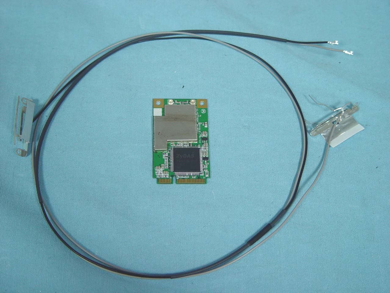
Click to zoom
Application Details
- Equipment Class
- DTS - Digital Transmission System
- Date of Grant
- Jul 23, 2006
- Application Purpose
- Original Equipment
- Date of Application
- Jul 19, 2006
- Equipment Note
- IEEE 802.11 b+g mini Card
- Frequency Range
- 2412.00000000 - 2462.00000000
- Company
- ZyDAS Technology Corporation
- Country
- Taiwan
Documents & Files
Document Text
Text extracted from the exhibit documents filed with the FCC. Open a document above to read the original.
Users Manual
Ver 0.3 ZyDAS WLAN Solution Doc. No.WLANUS1211 ZyDAS Confidential Information 1 2006/7/13 84 ZyDAS WLAN Solution ZDWlan_1211B-QF-F User Guide Version 0.3 ZyDAS ZyDAS Technology Corporation Ver 0.3 ZyDAS WLAN Solution Doc. No.WLANUS1211 ZyDAS Confidential Information 2 2006/7/13 ZDWlan_1211B-QF-F User Guide 1. How to Install ZD1211B-QF-F driver and ZDWlan Utility: 1.1 Install: Phase 1 1.1.1 Copy the driver package (ex: 1211USB_Install_4214.exe) to any directory of NoteBooK (or PC). The 1211USB_Install_4214.exe can be used at ZD1211B-QF-F Chip Set Only. It can be run on the Win98, WinME, Win2000 or WinXP OS. Figure 1-1 1.1.2 Click the package “1211USB_Install_4116.exe” then appear the installation page shown as “Figure 1-1”. Ver 0.3 ZyDAS WLAN Solution Doc. No.WLANUS1211 ZyDAS Confidential Information 3 2006/7/13 Figure 1-2 1.1.3 Press the “next” icon of Figure 1-1, then the page shown as “Figure 1-2”. Select “ZD1211 Config Tool” or “ZD1211 Diver” or all of them to install by checking the items. Ver 0.3 ZyDAS WLAN Solution Doc. No.WLANUS1211 ZyDAS Confidential Information 4 2006/7/13 Figure 1-3 1.1.4 Press the “next ” icon of Figure 1-2, then the page shown as “Figure 1-3”. Press the “Continue Anyway ” button of Figure 1-3, to finish the first phase installation. 1.1.5 After finishing the phase 1 installation of the driver, the NoteBooK (or PC) with Win98 or WinME OS shall be restarted, but Win2000 or WinXP OS doesn’t need to be restarted. Ver 0.3 ZyDAS WLAN Solution Doc. No.WLANUS1211 ZyDAS Confidential Information 5 2006/7/13 1.2 Install: Phase 2 Figure 1-4 1.2.1 Insert the Wireless Card to slot of NB, then appear the installation page shown as “Figure 1-4”. For installing the driver automatically, please check the automation item. Ver 0.3 ZyDAS WLAN Solution Doc. No.WLANUS1211 ZyDAS Confidential Information 6 2006/7/13 Figure 1-5 1.2.2 When the automation item of “Figure 1-4” is selected, press “Next” button of the page, then the “Hardware Installation” page shown as “Figure 1-5”. Ver 0.3 ZyDAS WLAN Solution Doc. No.WLANUS1211 ZyDAS Confidential Information 7 2006/7/13 Figure 1-6 1.2.3 Press the “Continue Anyway ” button of Figure 1-5, then the page “Found New Hardware Wizard” shown as “Figure 1-6”. - Press the “Finish” button of “Figure 1-6” to finish the package installation. Ver 0.3 ZyDAS WLAN Solution Doc. No.WLANUS1211 ZyDAS Confidential Information 8 2006/7/13 2. How to use the ZDWlan Utility: ( Station) 2.1 If you use the WinXP OS , the “Zero Configuration” of WinXP will be disable first , then ZDWlan Utility can be used. Figure 2-1 2.2 Open the ZDWlan Utility from “ Start menu bar \Program List \ ZyDAS 1211 Tool “. The Window is shown as “Figure 2-1”. The adapter can be set at “Station” or “Access Point” Mode from the Mode drop down menu. Station mode is selected for the item. - You can site survey the neighboring SSID site by pressing the “Refresh”, then sites name and signals strength of available SSID sites are shown on the “Available Network” field. - Double click the SSID site from “Available Network” field, and the SSID can be connected directly. - The information of the SSID is shown on the “ Current Network Ver 0.3 ZyDAS WLAN Solution Doc. No.WLANUS1211 ZyDAS Confidential Information 9 2006/7/13 Information”. - Show the BSSID of connecting AP on the “Link Status” filed. - “Signal Strength” and “Link Quality” shown on diagrammatic curve, and described with percentage. - Record the number of Tx frames on the filed of “Tx Frame”. - Record the number of Rx frames on the filed of “Rx Frame”. Ver 0.3 ZyDAS WLAN Solution Doc. No.WLANUS1211 ZyDAS Confidential Information 10 2006/7/13 . Figure 2-2 2.3 Click “ More Setting “ icon of Figure 2-1 to enter “More setting “ window. The window is shown as “ Figure 2-2 ”. 2.3.1 “General Connection Setting” group: - Read the current status from the group if the “Change” button is not pressed. - Press “Change” button for modifying the status, when the modification is finished, press “Apply” to save it. The button “Change” and “Apply” is alternately shown on the same position. - Modify the SSID name from the “SSID” field. When use the item, the “any “will be unchecked previously. - Change the channel by drop down menu “ Channel”. When use the item, the Ad_Hoc Mode will be set previously. . - Select the transmission rate by “ Tx Rate” drop down menu. Ver 0.3 ZyDAS WLAN Solution Doc. No.WLANUS1211 ZyDAS Confidential Information 11 2006/7/13 - Select the “Ad_Hoc” or “Infrastructure” Mode by the “Network Type” drop down menu. - Select the “Enable WEP” or “Disable WEP” by the “Encryption” drop down menu. - Select the “Open System” , “Shared Key” mode or “Auto” from the “Authentication Mode” drop down menu. Figure 2-3 Ver 0.3 ZyDAS WLAN Solution Doc. No.WLANUS1211 ZyDAS Confidential Information 12 2006/7/13 Figure 2-4 2.3.2 Encryption Setting : 2.3.2.1 Press “WEP Encryption Setting” to enter the “WEP Key Setting” page shown as Figure 2-3. - Select the “Open System” , “Shared Key” mode or “Auto” from the “authentication Mode” drop down menu. - Press the “Change” button to modify the contents of “WEP Key setting”, when it is finished, press “Apply” to save it. The button “Change” and “Apply” is alternately shown on the same position. - Select which key length 64,128 or 256 bits will be modified or used by “Key Length” item. - Select which key set will be use by the field of “Default Key ID” Modify the 4 sets key depending on the selected key length on the field of “Key Value”. The key value is used the hexadecimal format. Ver 0.3 ZyDAS WLAN Solution Doc. No.WLANUS1211 ZyDAS Confidential Information 13 2006/7/13 - Select which key format “hexadecimal” or “ASCII” will be used from the “Key Format” . 2.3.2.2 Press “WPA Encryption Setting” to enter the “WPA Setting” page shown as Figure 2-4. - You can select the WPA authentication protocol “TLS” , “PEAP” or “TTLS” from “Protocol” filed. - “TLS” Setting: you don’t fill out the User name and Password fiel…
Text truncated - open the document above for the full version.
Cover Letter(s)
Date: July 7, 2006 Compliance Certification Services Certification Division 561F Monterey Road Morgan Hill, CA 95037 To whom it may concern: We, the undersigned, hereby authorize the Taiwan office of Compliance Engineering Services, Inc., d.b.a. Compliance Certification Services and hereafter referred to as CCS TW, to act on our behalf in all manners relating to application for equipment authorization, including signing of all documents relating to these matters. Any and all acts carried out by CCS TW on our behalf shall have the same effect as acts of our own. We, the undersigned, hereby certify that we are not subject to a denial of federal benefits, that includes FCC benefits, pursuant to Section 5301 of the Anti-Drug Abuse Act of 1988, 21 U.S.C. 853(a). In authorizing CCS TW as our agent, we still recognize that we are responsible to: a) Comply with the relevant provisions of the certification program; b) Make all necessary arrangements for the conduct of the evaluation, including provision for examining documentation and access to all areas, records (including internal audit reports) and personnel for the purposes of evaluation (e.g. testing, inspection, assessment, surveillance, reassessment) and resolution of complaints; c) Make claims regarding certification only in respect of the scope for which certification has been granted; d) Do not use our product certification in such a manner as to bring the Certification Division into disrepute and not make any statement regarding our product certification which the Certification Division may consider misleading or unauthorized; e) Upon suspension or cancellation of certification, discontinue use of all advertising matter that contains any reference thereto and return any certification documents as required by the Certification Division; f) Use certification only to indicate the products are certified as being in conformity with specified standards; g) Endeavor to ensure that no certificate or report nor any part thereof is used in a misleading manner; h) Ensure that any reference to our product certification in communication media such as documents, brochures or advertising, complies with the requirements of the Certification Division; i) Keep a record of all complaints made known to the us relating to the product’s compliance with requirements of the relevant standard and to make these records available to the Certification Division when requested; j) Take appropriate action with respect to such complaints and any deficiencies found in products or services that affect compliance with the requirements for certification; k) Document the actions taken. This authorization is valid until further written notice from the applicant. Sincerely Yours, Reggie Hsieh/ Marketing & Sales Department/Account Manager ZyDAS Technology Corporation
Cover Letter(s)
2F,No.15,Industry E. Rd. IV,Hsinchu Science Park, Hsin-Chu,300,Taiwan, R.O.C. Te l e p h o n e n o:886-3-5773309 Fax no:886-3-5773767 July 7,2006 Federal Communications Commission Authorization and Evaluation Division FCC ID: TXG-ZD1211B-QF-F Confidentiality Request Pursuant to Sections 0.457 and 0.459 of the Commission’s Rules, the Applicant hereby requests confidential treatment of information accompanying this Application as outlined below: 1. Schematics 2. Operational Description 3. Block Diagram The above materials contain trade secrets and proprietary information not customarily released to the public. The public disclosure of these matters might be harmful to the Applicant and provide unjustified benefits to its competitors. The Applicant understands that pursuant to Rule 0.457, disclosure of this Application and all accompanying documentation will not be made before the date of the Grant for this application. Sincerely, Reggie Hsieh/ Marketing & Sales Department/Account Manager ZyDAS Technology Corporation
Cover Letter(s)
Modular Approval Request Letter July 7, 2006 Compliance Certification Services 561F Monterey Rd., Morgan Hill, CA 95037, USA To Whom It May Concern: Please be advised that IEEE 802.11 b+g mini card , with the FCC ID: TXG-ZD1211B-QF-F would be certified as the Modular Approval with the Mobile device classification. User shall be informed that keeping at least 20cm safe separation away the device. We also assure the device complies with the requirements listed in the Public Notice DA-00-1407, details are listed as follows: 1. The modular transmitter must have its own RF shielding: Reply: The radio portion of this module has been shielded, please see exhibition External Photo. 2. The modular transmitter must have buffered modulation / data inputs: Reply: The EUT has buffered data inputs, it is integrated in chip ZD1211B-QF-F. 3. The modular transmitter must have its own power supply regulation: Reply: The transceiver which will influence the frequency radiation, have to be 2.8V DC powered. The minicard interface provides 3.3VDC, so there is regulator in front of transceiver, the part number of this regulator is R1114N281D. 4. The modular transmitter must comply with the antenna requirements of the Section 15.203 and 15.204(c): Reply: The EUT meets the FCC antenna requirements. The spurious emission, unique antenna connector and photo of antennas are shown in the External and Internal Photos. 5. The modular transmitter must be tested in a stand-alone configuration: Reply: The EUT was tested in a stand-alone configuration via a PCMCIA to mini-PCI extender. Please see section Photographs of Test Configuration in the test report, the EUT was plugged in this extender. 6. The modular transmitter must be labeled with its own FCC ID number: Reply: That is label show “Contains FCC ID: TXG-ZD1211B-QF-F”in the end product. 7. The modular transmitter must comply with any specific rule or operating requirements applicable to the transmitter and the manufacturer must provide adequate instructions along with the module to explain any such requirements: Reply: The EUT is compliant with all applicable FCC rules. Detail instructions for maintaining compliance are given in the Users Manual. 8. The modular transmitter must comply with any applicable RF exposure requirements: Reply: For mobile configuration only. Refer to MPE calculation in the test report. RF Exposure is addressed in the RF exposure exhibition. Should you have any question, please don’t hesitate to ask us. Best regards, Sincerely Yours, Reggie Hsieh/ Marketing & Sales Department/Account Manager ZyDAS Technology Corporation
External Photos
Compliance Certification Services Inc. Report No: 60613006 Date of Issue: July 4, 2006 Page 1 Total Page: 4 Rev. 00 EXTERNAL PHOTOGRAPHS OF EUT Compliance Certification Services Inc. Report No: 60613006 Date of Issue: July 4, 2006 Page 2 Rev.00 Compliance Certification Services Inc. Report No: 60613006 Date of Issue: July 4, 2006 Page 3 Rev.00
ID Label/Location Info
Contains RF module FCC ID: TXG-ZD1211B-QF-F ~4178729.ufo
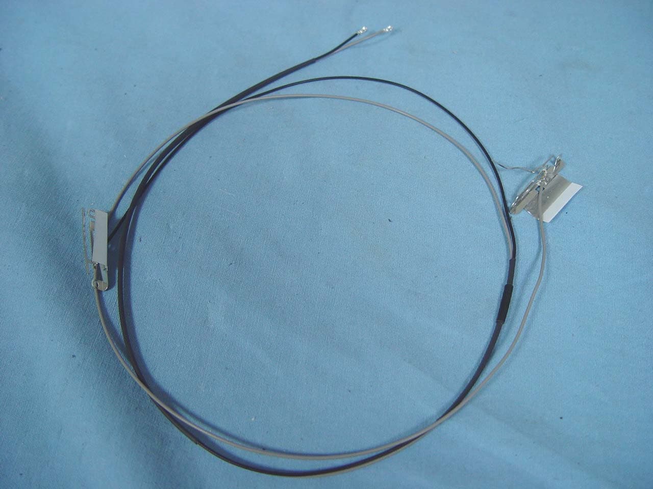
Internal Photos
Compliance Certification Services Inc. Report No: 60613006 Date of Issue: July 4, 2006 Page 4 Rev.00 INTERNAL PHOTOGRAPHS OF EUT
Parts List/Tune Up Info
Doc.No.:3.8.05 Rev – 6.0 Regulatory WLAN Antenna Information 1/28 Regulatory WLAN Antenna Information (English Language Required for Intel Regulatory Review / Approval) Brand Name Quanta Model Name TW3 Antenna Vendor Foxconn Antenna Part Number Main Antenna: WDAN-Q1TW3001-DF Aux Antenna: WDAN-Q1TW3001-DF With WLAN Module □ WM3B2100 (Check Box) □ WM3B2200BG □ WM3B2915ABG □ WM3945ABG Doc.No.:3.8.05 Rev – 6.0 Regulatory WLAN Antenna Information 2/28 Antenna Sample / Antenna Data Requirements for worldwide regulatory approval Section Description of Required OEM / ODM Antenna Information US / ICEU Japan Taiwan S.Korea 1A Part Number for Antenna only RequiredRequiredRequired Required Required 1B Antenna Manufacturer Name RequiredRequiredRequired Required Required 1C Description of Antenna Type RequiredN/A N/A N/A N/A 1D Part number of Antenna Assembly / cable impedance, length & diameter. RequiredDesiredDesired Desired Desired 1E Main & Aux antenna (Peak Gain W/ cable loss) RequiredRequiredRequired Required Required 1E OR 1F, 1G, 1H 1F Main & Aux antenna (Peak Gain only) RequiredRequiredRequired Required Required 1G VSWR of cable including connector RequiredRequiredRequired Required Required 1H Main & Aux antenna (Cable loss W/ connector) RequiredRequiredRequired Required Required 2 Dimensioned Photographs and Drawings of main & auxiliary antennas RequiredRequiredRequired Required Required 3 Radiation patterns of antennas loaded in the host platform. RequiredDesiredRequired N/A Required 4 Platform model name / number - correlated to antenna manufacturer and antenna part number RequiredRequiredDesired Required Desired 5 Photograph(s) or Drawings showing location of antennas in platform. (S. Korea requires photographs of antennas for approval submission). Taiwan requires pictures of each antenna type shown in the system. RequiredRequiredDesired Required (Photos) Required (Photos) 6 Mech. drawings / photos with dimensions of antenna locations and distance from end-user (For evaluation of SAR testing requirement). RequiredN/A N/A N/A N/A 7 Photograph(s) or Drawings showing the location of all antennas (WLAN, BT, other) and distance between those transmitting antennas. Information will be used to evaluate whether co-location testing is required. RequiredN/A N/A N/A N/A 8 Local representative contact information for LMA/ PARS process. RequiredN/A N/A N/A N/A Doc.No.:3.8.05 Rev – 6.0 Regulatory WLAN Antenna Information 3/28 Antenna Information Section 1. Antenna Assembly Specifications Antenna Assembly Summary: 1A Antenna Part Number 1B Manufacture 1C Antenna Type 1D Cable Assembly Part Number and Information 1E *Peak Gain W/ Cable loss (dBi) 1F Peak Gain w/o Cable Loss (dBi) 1G VSWR 1H Cable Loss (dBi) 2400-2488MHz 1.62 dBi (peak) 2400-2488MHz 3.385 dBi (peak) 2400-2488MHz 2.0 max 2400-2488MHz -1.765 dBi (peak) 4900-5350MHz 1.26 dBi (peak) 4900-5350MHz 3.919 dBi (peak) 4900-5350MHz 2.0 max 4900-5350MHz -2.659 dBi (peak) (P/N: WDAN-Q1TW30 01-DF) Main antenna HON HAI PRECISION IND. CO.,LTD. PIFA 1. Cable P/N: FOXCONN: 703-3200-211 2. Cable type: 32 AWG O,D. 1.13 mm 50 ohm coaxial cable 3. Cable length:650mm 4. Connector P/N: SGX0001-00 5470-5875MHz 0.19 dBi (peak) 5470-5875MHz 2.94 dBi (peak) 5470-5875MHz 2.0 max 5470-5875MHz -2.75 dBi (peak) 2400-2488MHz 0.23 dBi (peak) 2400-2488MHz 2.714 dBi (peak) 2400-2488MHz 2.0max 2400-2488MHz -2.484 dBi (peak) 4900-5350MHz 0.05 dBi (peak) 4900-5350MHz 3.794 dBi (peak) 4900-5350MHz 2.0 max 4900-5350MHz -3.744 dBi (peak) (P/N: WDAN-Q1TW30 01-DF) Auxiliary antenna HON HAI PRECISION IND. CO.,LTD. PIFA 1. Cable P/N: FOXCONN: 703-3208-211 2. Cable type: 32 AWG O,D. 1.13 mm 50 ohm coaxial cable 3. Cable length: 915mm 3. Connector P/N: SGX0001-00 5470-5875MHz -0.96 dBi (peak) 5470-5875MHz 2.912 dBi (peak) 5470-5875MHz 2.0 max 5470-5875MHz -3.872 dBi (peak) Antenna Peak Gain Table: Main antenna Aux Antenna Frequency (MHz) Horizontal (dBi) Vertical (dBi) Hori+Ver (dBi) Horizontal (dBi) Vertical (dBi) Hori+Ver (dBi) 2400 -1.03 -0.65 0.85 -1.71 -1.64 0.23 2444 -0.17 -0.39 1.62 -2.03 -2.07 -0.5 2488 -0.61 0.21 1.08 -3.02 -3.11 -1.51 4900 -0.27 -2.97 1.26 -0.49 -4.84 0.05 5125 -1.88 -0.01 1.12 -1.33 -2.38 -0.72 5350 -2.17 -2.07 -0.28 -2.73 -3.36 -0.96 5470 -1.64 -1.98 0.19 -2.86 -3.28 -0.96 5673 -1.74 -1.82 0.15 -2.76 -2.66 -1.04 5875 -2.63 -1.39 -0.01 -3.65 -3.7 -2.13 z Antenna Peak Gain required being test in system basis. z 1E frame contend absolutely peak antenna gain include H/ V/ H+V. Doc.No.:3.8.05 Rev – 6.0 Regulatory WLAN Antenna Information 4/28 Section 2. Dimensioned Photos or Drawings of Antennas Include a dimensioned photo and dimensioned drawing of main antenna here. Antenna Dimensioned Drawing: Main Antenna Photo: ( Aux Antenna ) ( Main Antenna ) Doc.No.:3.8.05 Rev – 6.0 Regulatory WLAN Antenna Information 5/28 Section 3. Radiation characteristics of antenna Loaded in Host Platform 2400-2500MHz radiation characteristic Main antenna: 2400 MHz Center Frequency 2400 MHz Horizontal (dBi) peak -1.03 Vertical (dBi) peak -0.65 Horz+Vert (dBi) peak 0.85 Doc.No.:3.8.05 Rev – 6.0 Regulatory WLAN Antenna Information 6/28 Main antenna: 2444 MHz Center Frequency 2444 MHz Horizontal (dBi) peak -0.17 Vertical (dBi) peak -0.39 Horz+Vert (dBi) peak 1.62 Doc.No.:3.8.05 Rev – 6.0 Regulatory WLAN Antenna Information 7/28 Main antenna: 2488 MHz Center Frequency 2488 MHz Horizontal (dBi) peak -0.61 Vertical (dBi) peak 0.21 Horz+Vert (dBi) peak 1.08 Doc.No.:3.8.05 Rev – 6.0 Regulatory WLAN Antenna Information 8/28 Auxiliary antenna: 2400 MHz Center Frequency 2400 MHz Horizontal (dBi) peak -1.71 Vertical (dBi) peak -1.64 Horz+Vert (dBi) peak 0.23 Doc.No.:3.8.05 Rev – 6.0 Regulatory WLAN Antenna Information 9/28 Auxiliary antenna: 2444 MHz Center Frequency 2444 MHz Horizontal (dBi) peak -2.03 Vertical (dBi) peak -2.07 Horz+Vert (dBi) peak -0.5 Doc.No.:3.8.05 Rev – 6.0 Regulatory WLAN Antenna Information 10/28 Auxiliary antenna: 2488 MHz Center Frequency 2500 MHz Horizontal (dBi) p…
Text truncated - open the document above for the full version.
Test Report
Compliance Certification Services Inc. Report No.: 60613006-RP1 FCC ID: TXG-ZD1211B-QF-F Date of Issue: July 3, 2006 Note: This report shall not be reproduced except in full, without the written approval of Compliance Certification Services Inc. This document may be altered or revised by Compliance Certification Services Inc. personnel only, and shall be noted in the revision section of the document. Page 1 Total Page: 58 Rev. 00 FCC 47 CFR PART 15 SUBPART C TEST REPORT For IEEE 802.11 b+g mini card Model: ZD1211B-QF-F Trade Name: ZyDAS Issued to ZyDAS Technology Corporation 2F,No.15,Industry E. Rd. IV, Hsinchu Science Part, Hsinchu,Taiwan, R.O.C. Issued by Compliance Certification Services Inc. No. 81-1, Lane 210, Bade Rd. 2, Luchu Hsiang, Taoyuan Hsien, (338) Taiwan, R.O.C. http://www.ccsemc.com.tw [email protected] Compliance Certification Services Inc. Report No.: 60613006-RP1 FCC ID: TXG-ZD1211B-QF-F Date of Issue: July 3, 2006 Page 2 Rev. 00 TABLE OF CONTENTS 1. TEST RESULT CERTIFICATION....................................................................................................3 2. EUT DESCRIPTION ...........................................................................................................................4 3. TEST METHODOLOGY ....................................................................................................................5 3.1 EUT CONFIGURATION........................................................................................................................5 3.2 EUT EXERCISE....................................................................................................................................5 3.3 GENERAL TEST PROCEDURES.............................................................................................................5 3.4 FCC PART 15.205 RESTRICTED BANDS OF OPERATIONS........................................................6 3.5 DESCRIPTION OF TEST MODES...........................................................................................................6 4. INSTRUMENT CALIBRATION........................................................................................................7 4.1 MEASURING INSTRUMENT CALIBRATION......................................................................................7 4.2 MEASUREMENT EQUIPMENT USED.........................................................................................7 5. FACILITIES AND ACCREDITATIONS ..........................................................................................8 5.1 FACILITIES .........................................................................................................................................8 5.2 EQUIPMENT........................................................................................................................................8 5.3 TABLE OF ACCREDITATIONS AND LISTINGS.......................................................................................9 6. SETUP OF EQUIPMENT UNDER TEST .......................................................................................10 6.1 SETUP CONFIGURATION OF EUT.......................................................................................................10 6.2 SUPPORT EQUIPMENT ...............................................................................................................10 7. FCC PART 15.247 REQUIREMENTS.............................................................................................11 7.1 6DB BANDWIDTH.............................................................................................................................11 7.2 PEAK POWER....................................................................................................................................15 7.3 AVERAGE POWER............................................................................................................................19 7.4 BAND EDGES MEASUREMENT ................................................................................................23 7.5 PEAK POWER SPECTRAL DENSITY....................................................................................................32 7.6 SPURIOUS EMISSIONS ................................................................................................................37 7.7 POWERLINE CONDUCTED EMISSIONS...............................................................................................51 APPENDIX I RADIO FREQUENCY EXPOSURE ...............................................................................54 APPENDIX II PHOTOGRAPHS OF TEST SETUP .............................................................................56 Compliance Certification Services Inc. Report No.: 60613006-RP1 FCC ID: TXG-ZD1211B-QF-F Date of Issue: July 3, 2006 Page 4 Rev. 00 2. EUT DESCRIPTION Product IEEE 802.11 b+g mini card Trade Name ZyDAS Model Number ZD1211B-QF-F Model Discrepancy N/A Power Supply Powered from host device. Frequency Range 2412 ~ 2462 MHz Transmit Power IEEE 802.11b: 19.83 dBm IEEE 802.11g: 18.71 dBm Modulation Technique IEEE 802.11b: DSSS (CCK, DQPSK, DBPSK) IEEE 802.11g: DSSS (CCK, DQPSK, DBPSK) + OFDM (QPSK, BPSK, 16-QAM, 64-QAM) Transmit Data Rate IEEE 802.11b: 11, 5.5, 2, 1 Mbps IEEE 802.11g: 54, 48, 36, 24, 18, 12, 11, 9, 6, 5.5, 2, 1 Mbps Number of Channels 11 Channels Antenna Specification Gain: 1.62 dBi Antenna Designation PIFA Antenna Remark: 1. The sample selected for test was engineering sample that approximated to production product and was provided by manufacturer. 2. This submittal(s) (test report) is intended for FCC ID: TXG-ZD1211B-QF-F filing to comply with Section 15.207, 15.209 and 15.247 of the FCC Part 15, Subpart C Rules. Compliance Certification Services Inc. Report No.: 60613006-RP1 FCC ID: TXG-ZD1211B-QF-F Date of Issue: July 3, 2006 Page 5 Rev. 00 3. TEST METHODOLOGY The tests documented in this report were performed in accordance with ANSI…
Text truncated - open the document above for the full version.
Test Setup Photos
Compliance Certification Services Inc. Report No.: 60613006-RP1 FCC ID: TXG-ZD1211B-QF-F Date of Issue: July 3, 2006 Page 56 Rev. 00 APPENDIX II PHOTOGRAPHS OF TEST SETUP Conducted Emissions Setup Photos Compliance Certification Services Inc. Report No.: 60613006-RP1 FCC ID: TXG-ZD1211B-QF-F Date of Issue: July 3, 2006 Page 57 Rev. 00 Radiated Emissions Setup Photos Compliance Certification Services Inc. Report No.: 60613006-RP1 FCC ID: TXG-ZD1211B-QF-F Date of Issue: July 3, 2006 Page 58 Rev. 00 Powerline Conducted Emissions Setup Photos
Contact Information
Applicant
Reggie Hsieh(Account Manager)
Test Firm
Compliance Certification Services Inc.Harris Lai
Technical Specifications
| # | Rule Parts | Frequency Range | Power Output |
|---|---|---|---|
| 1 | 15C | 2.41 GHz - 2.46 GHz | 96.16 mW |
Other Applications from ZyDAS Technology Corporation
TXG-ZD1211B-QF-F2
Sep 06, 2006IEEE 802.11b+g Mini Card
Equipment Class
DTS - Digital Transmission System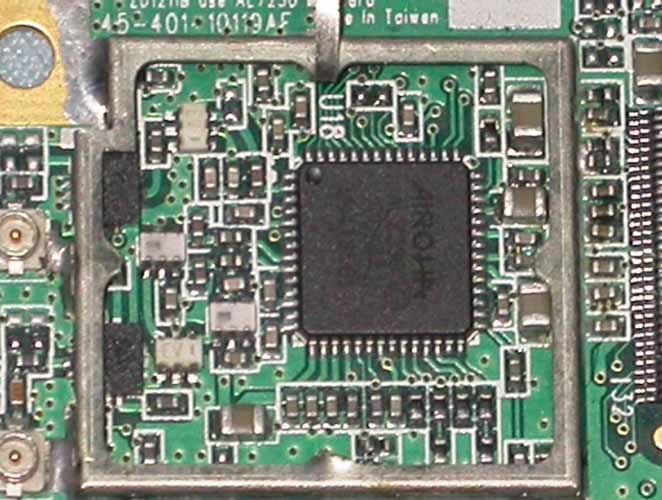
TXG-ZD1211B-QF-E
Apr 13, 2006IEEE 802.11 a+b+g (dual band) mini card
Equipment Class
DTS - Digital Transmission System