TXH-5016550165
Cognex Germany Aachen GmbH
Click to zoom
Application Details
- Equipment Class
- DTS - Digital Transmission System
- Date of Grant
- Jan 17, 2022
- Application Purpose
- Original Equipment
- Date of Application
- Oct 28, 2021
- Equipment Note
- 50165
- Frequency Range
- 2412.00000000 - 2462.00000000
- Company
- Cognex Germany Aachen GmbH
- Country
- Germany
Documents & Files
Document Text
Text extracted from the exhibit documents filed with the FCC. Open a document above to read the original.
Users Manual
Cognex Corporation One Vision Drive Natick, MA 01760-2059 (508) 650-3000 fax (508) 650-3333 www.cognex.com Wireless Module 50165 Integration Manual Revision: Rev04 Date: 2022/01/10 Model: 50165 Trademark: COGNEX 1 Description: General The 50165 wireless module is designed based on B-Link BL-M3455AT1(BL-6255) using a Cypress CYW43455 chipset. It operates in 2.4GHz band for BT classic/ BT LE and WiFi and in the 5GHz band for Wifi. The module supports standard SDIO v3.0 interfaces, backward compatible with SDIO v2.0 and supports a high-speed UART interface. Front Side With Shield Front Side Without Shield Back Side 5 5 5 Cognex Corporation One Vision Drive Natick, MA 01760-2059 (508) 650-3000 fax (508) 650-3333 www.cognex.com The module uses a PCB antenna that provides with max 3.4 dBi gain in the frequency range from 2412-2472 MHz and 5.18-5.835GHz. Features Supports with SDIO2.0/3.0; Supports a high-speed UART interface for Bluetooth 4.1 Supports IEEE 802.11a/b/g/n/ac Operating frequencies: 2.4~2.4835GHz & 5.18-5.835GHz Build in PCB Antenna with 3.4 dBi gain Applications Cognex DM8700 series Handheld Readers Cognex DM8700 series Base Stations 2 Functional Block Diagram The 50165 has two crystals. One 32.768 kHz low power oscillator for low power mode timing and one 37.4 MHz reference clock. Via the connector the module is powered with 5VDC and internally 3.3VDC are generated and filtered. The wireless connectivity is based on the B-Link BL- M3455AT1(BL-6255) chip. Cognex Corporation One Vision Drive Natick, MA 01760-2059 (508) 650-3000 fax (508) 650-3333 www.cognex.com 3 Antenna Specification 4 Pin Assignments Pin Function Description 1 +5V Main power source input 2 +5V Main power source input 3 +5V Main power source input 4 SDIO_D0 SDIO Interface 5 UART_CTS UART Interface 6 SDIO_D1 SDIO Interface 7 UART1_RXD UART Interface 8 SDIO_D2 SDIO Interface 9 UART1_TXD UART Interface 10 SDIO_D3 SDIO Interface 11 UART_RTS UART Interface 12 SDIO_CMD SDIO Interface 13 I2C_SDA I2C interface 14 SDIO_CLK SDIO Interface 15 I2C_SCL I2C interface 16 WAKE Module wake-up host 17 GND Ground 18 GND Ground 19 GND Ground 20 GND Ground Cognex Corporation One Vision Drive Natick, MA 01760-2059 (508) 650-3000 fax (508) 650-3333 www.cognex.com 5 Application Information Supported Platforms: Cognex products using Linux based operating systems based on ARM CPU framework. Integration Information: UART 50165 provides with a high-speed 4-wire CTS/RTS UART interface. It is compatible with the industry standard 16550 UART. SDIO 50165 provides support for SDIO version 3.0, including the new UHS-I modes: DS: Default speed (DS) up to 25 MHz, including 1- and 4-bit modes (3.3 V signaling). HS: High speed up to 50 MHz (3.3 V signaling). Mechanical For integration in Cognex Handheld Readers keep a minimum clearance of 1.6mm and a maximum clearance of 2mm between outer round shape of the module and Readers main plastic housing. Main housing thickness should be 3.7 +/-1mm For integration in Cognex Base Stations use part number 1000001866 underneath the 50165 Cognex Corporation One Vision Drive Natick, MA 01760-2059 (508) 650-3000 fax (508) 650-3333 www.cognex.com Or at least a similar supporting structure underneath the module in the same shape made of Makrolon 2405 and 4.9 +/- 0.1mm thickness. Labeling The module is labeled with FCC ID, IC ID and model name: Integrators have to label End-devices with: Contains FCC ID: TXH-50165; IC: 6315A-50165 Labeling shall be clear and legible and shall resist the effects of the cleaning agents specified by the End-device Manual. Warnings: FCC § 15.19 Labelling requirements This device complies with part 15 of the FCC Rules and Industry Canada license-exempt RSS standard(s). Operation is subject to the following two conditions: (1) This device may not cause harmful interference, and (2) this device must accept any interference received, including interference that may cause undesired operation. FCC § 15.21 Information to user Changes or modifications not expressly approved by the party responsible for compliance could void the user’s authority to operate the equipment. Wireless chipset Label Cognex Corporation One Vision Drive Natick, MA 01760-2059 (508) 650-3000 fax (508) 650-3333 www.cognex.com FCC RF Exposure: To comply with FCC RF exposure requirements, a minimum separation distance of 35mm must be maintained between the user's hand and the integral antenna of the device during normal handling of the device. For more information about RF exposure, please visit the FCC website at www.fcc.gov ISED Statements (Canada) Le présent appareil est conforme aux Innovation, Science and Economic Development Canada applicables aux appareils radio exempts de licence. L'exploitation est autorisée aux deux conditions suivantes: (1) l'appareil ne doit pas produire de brouillage, et (2) l'utilisateur de l'appareil doit accepter tout brouillage radioélectrique subi, même si le brouillage est susceptible d'en compromettre le fonctionnement. ESD CAUTION: Although this module is designed to be as robust as possible, Electrostatic Discharge (ESD) can damage this module. It must be protected from ESD at all times and handled under the protectionof ESD.
Cover Letter(s)
Cognex Corporation One Vision Drive Natick, MA 01760-2059 (508) 650-3000 fax (508) 650-3333 www.cognex.com FCC AGENCY AUTHORIZATION LETTER We Name: Cognex Germany Aachen GmbH Address: Krefelder Strasse 218 City: 52070 Aachen Country: Germany Declare that: Name Representative of agent: Imad Hjije, Abdellah Ahakki, Teoman Soner-Sunar (1) Agent Company name: 7layers GmbH Address: Borsigstr. 11 City: 40880 Ratingen Country Germany is authorized to apply for Certification of the following product(s): Product description: Wireless module for Cognex industrial vision systems. Type designation: 50165 Trademark: COGNEX on our behalf. Date: 08.06.2021 City: Aachen Name: Simon Jünger (2) Function: Principal Compliance Engineer Signature: . Notes: (1): Required for FCC application (2): For FCC it must be the Grantee Code “owner” or the authorized agent.
Cover Letter(s)
FCC, Request for non-disclosure Date: 21-Nov-2018 RF_501, Issue 8 Page 1 of 1 Company Name: Cognex Germany Aachen GmbH Address: Krefelder Strasse 218 City: Aachen Country: Germany To: Telefication B.V., Dept. FCC TCB Edisonstraat 12A 6902 PK ZEVENAAR The Netherlands Subject: Request for confidentiality FCC ID: TXH-50165 Reference number: ###### Dear FCC TCB, 1. Long-Term Confidentiality Pursuant to 47 CFR Section 0.459(a) & (b), we hereby requests non-disclosure and confidential treatment of the following materials submitted in support of FCC certification application: Bill(s) of Material Block Diagrams Operational Description Schematic Diagrams Tune-up Procedure Above materials contain secrets, proprietary and technical information, which would customarily be guarded from competitors under 47 CFR, section 0.457(d)(2). Disclosure or publication or any portion of this company confidential material to other parties could cause substantial competitive harm and provide unjustified benefits for competitors. 2. Short-Term Confidentiality (STC) Pursuant to Public Notice DA 04-1705 of the Commission’s policy, in order to comply with the marketing regulations in 47 CFR §2.803 and the importation rules in 47 CFR §2.1204, applicant hereby requests Short-Term Confidential treatment of the following materials (See notes below): Internal Photos User’s Manual Test Set-up Photos External Photos Justification: Protection from competitors Date: 08/17/2020 Name and signature of applicant: Imad Hjije Notes: 1) A document or type of document can only have ONE type of confidentiality! 2) Short-Term confidentiality is in principle for 45 days from date of grant; it can be extended max 3 times (total time 180 days max.)! The planned date should stated in the RF731 application form. 3) FCC must be informed when marketing begins earlier. 4) Release takes place automatically thus extension must be requested in time. Telefication does not remind you of this! 5) Request for extension or for release must be received by Telefication at least 7 days before date of actual marketing or before expiration of the STC period
Cover Letter(s)
RF_734_02 04 April 16 Modular Approval Request FCC (KDB 996369 D01 & Part 15.212) FCC ID: TXH-50165 Items to be covered by Single modular transmitters. Answer from applicant 1. The modular transmitter must have its own RF shielding. Yes 2. The modular transmitter must have buffered modulation/data inputs (if such inputs are provided) to ensure that the module will comply with Part 15 requirements under conditions of excessive data rates or over-modulation. Yes 3. The modular transmitter must have its own power supply regulation. Yes 4. The modular transmitter must comply with the antenna requirements of Section 15.203 and 15.204(b)(c). The antenna must either be permanently attached or employ a “unique” antenna coupler (at all connections between the module and the antenna, including the cable). Yes 5. The modular transmitter must be tested in a stand-alone configuration, i.e., the module must not be inside another device during testing. This is intended to demonstrate that the module is capable of complying with Part 15 emission limits regardless of the device into which it is eventually installed. Yes 6. The modular transmitter must be equipped with either a permanently affixed label or must be capable of electronically displaying its FCC identification number in accordance with 15.212 (a)(1)(vi)(A) / (B). Yes 7. The modular transmitter must comply with any specific rule or operating requirements applicable to the transmitter and the manufacturer must provide adequate instructions along with the module to explain any such requirements. A copy of these instructions must be included in the application for equipment authorization. For example, there are very strict operational and timing requirements that must be met before a transmitter is authorized for operation under Section 15.231. For instance, data transmission is prohibited, except for operation under Section 15.231(e), in which case there are separate field strength level and timing requirements. Compliance with these requirements must be assured. Yes 8. The modular transmitter must comply with any applicable RF exposure requirements. For example, FCC Rules in Sections 1.1310, 2.1091, 2.1093, and specific Sections of Part 15, including 15.319(i), 15.407(f), 15.253(f) and 15.255(g), require that Unlicensed PCS, UNII and millimeter wave devices perform routine environmental evaluation for RF Exposure to demonstrate compliance. In addition, spread spectrum transmitters operating under Section 15.247 are required to address RF Exposure compliance. Modular transmitters approved under other Sections of Part 15, when necessary, may also need to address certain RF Exposure concerns, typically by providing specific installation and operating instructions for users, installers and other interested parties to ensure compliance. Yes RF_734_02 04 April 16 Items to be covered by Split modular transmitters. Answer from applicant 1. The modular transmitter must comply with all requirements of a single modular transmitter except for items (1) & (5) of the above single modular approval requirements. 2. Only the radio front end must be shielded. The physical crystal and tuning capacitors may be located external to the shielded radio elements. The interface between the split sections of the modular system must be digital with a minimum signalling amplitude of 150 mV peak-to-peak. 3. Control information and other data may be exchanged between the transmitter control elements and radio front end. 4. The sections of a split modular transmitter must be tested installed in a host device(s) similar to that which is representative of the platform(s) intended for use. 5. Manufacturers must ensure that only transmitter control elements and radio front end components that have been approved together are capable of operating together. The transmitter module must not operate unless it has verified that the installed transmitter control elements and radio front end have been authorized together. Manufacturers may use means including, but not limited to, coding in hardware and electronic signatures in software to meet these requirements, and must describe the methods in their application for equipment authorization. Note: A limited modular approval (LMA) may be granted for single or split modular transmitters that comply partially with the requirements above. Name and surname of applicant (or authorized representative): Imad Hjije Date: 08/17/2021 Signature:
RF Exposure Info
RF Exposure – Mobile and Portable devices Model: 50165 FCC ID: TXH-50165 The module will be integrated into hosts used at a distance of at least 35 mm from the human body. Maximum output power measured for 2.4 GHz is 43.652 mW. For 5 GHz it is 42.658 mW. Therefore, the host integrating this module is exempted from SAR as per KDB 447498 D01 General RF Exposure Guidance v06. Yous sincerely, Imad Hjije
Test Report
Test Laboratory: 7layers GmbH Borsigstrasse 11 40880 Ratingen Germany Note: The following test results relate only to the devices specified in this document. This report shall not be reproduced in parts without the written approval of the test laboratory. 7layers GmbH Geschäftsführer/ Borsigstraße 11 Managing Directors: Registergericht/registered: a Bureau Veritas 40880 Ratingen, Germany Frank Spiller Düsseldorf HRB 75554 Group Company T +49 (0) 2102 749 0 Bernhard Retka USt-Id.-Nr./VAT-No. DE203159652 F +49 (0) 2102 749 350 Alexandre Norré-Oudard Steuer-Nr./TAX-No. 147/5869/0385 www.7layers.com Commerzbank AG Account No. 303 016 000 Bank Code 300 400 00 IBAN DE81 3004 0000 0303 0160 00 Swift Code COBADEFF FCC Measurement/Technical Report on 50165 Bluetooth ® / Bluetooth ® Low Energy / WLAN Wireless Module FCC ID: TXH-50165 IC: 6315A-50165 Test Report Reference: MDE_COGNEX_1803_FCC_05 TEST REPORT REFERENCE: MDE_COGNEX_1803_FCC_05 Page 2 of 73 Table of Contents 1 Applied Standards and Test Summary 3 1.1 Applied Standards 3 1.2 FCC-IC Correlation Table 4 1.3 Measurement Summary 5 2 Revision History / Signatures 9 3 Administrative Data 10 3.1 Testing Laboratory 10 3.2 Project Data 10 3.3 Applicant Data 10 3.4 Manufacturer Data 10 4 Test object Data 11 4.1 General EUT Description 11 4.2 EUT Main components 12 4.3 Ancillary Equipment 12 4.4 Auxiliary Equipment 13 4.5 EUT Setups 14 4.6 Operating Modes / Test Channels 14 4.7 Product labelling 14 4.8 Duty Cycle Plots 15 5 Test Results 18 5.1 Conducted Emissions at AC Mains 18 5.2 Occupied Bandwidth (6 dB) 23 5.3 Occupied Bandwidth (99%) 26 5.4 Peak Power Output 29 5.5 Spurious RF Conducted Emissions 33 5.6 Transmitter Spurious Radiated Emissions 37 5.7 Band Edge Compliance Conducted 47 5.8 Band Edge Compliance Radiated 53 5.9 Power Density 59 6 Test Equipment 63 7 Antenna Factors, Cable Loss and Sample Calculations 67 7.1 LISN R&S ESH3-Z5 (150 kHz – 30 MHz) 67 7.2 Antenna R&S HFH2-Z2 (9 kHz – 30 MHz) 68 7.3 Antenna R&S HL562 (30 MHz – 1 GHz) 69 7.4 Antenna R&S HF907 (1 GHz – 18 GHz) 70 7.5 Antenna EMCO 3160-09 (18 GHz – 26.5 GHz) 71 7.6 Antenna EMCO 3160-10 (26.5 GHz – 40 GHz) 72 8 Photo Report 72 9 Measurement Uncertainties 73 TEST REPORT REFERENCE: MDE_COGNEX_1803_FCC_05 Page 3 of 73 1 APPLIED STANDARDS AND TEST SUMMARY 1.1 APPLIED STANDARDS Type of Authorization Certification for an Intentional Radiator. Applicable FCC Rules Prepared in accordance with the requirements of FCC Rules and Regulations as listed in 47 CFR Ch.1 Parts 2 and 15 (10-1-19 Edition). The following subparts are applicable to the results in this test report. Part 2, Subpart J - Equipment Authorization Procedures, Certification Part 15, Subpart C – Intentional Radiators § 15.201 Equipment authorization requirement § 15.207 Conducted limits § 15.209 Radiated emission limits; general requirements § 15.247 Operation within the bands 902-928 MHz, 2400-2483.5 MHz Note: The tests were selected and performed with reference to the FCC Public Notice “Guidance for Compliance Measurements on Digital Transmission System, Frequency Hopping Spread Spectrum System, and Hybrid System Devices Operating under Section 15.247 of the FCC Rules, 558074 D01 15.247 Meas Guidance v05r02, 2019-04-02”. ANSI C63.10–2013 is applied. Note: This test report comprises the tests for WLAN technology. Bluetooth and Bluetooth Low Energy results have already been reported in other test reports. TEST REPORT REFERENCE: MDE_COGNEX_1803_FCC_05 Page 4 of 73 1.2 FCC-IC CORRELATION TABLE Correlation of measurement requirements for DTS (e.g. WLAN 2.4 GHz, BT LE) equipment from FCC and IC DTS equipment Measurement FCC reference IC reference Conducted emissions on AC Mains § 15.207 RSS-Gen Issue 5+A1+A2: 8.8 Occupied bandwidth § 15.247 (a) (2) RSS-247 Issue 2: 5.2 (a) Peak conducted output power § 15.247 (b) (3), (4) RSS-247 Issue 2: 5.4 (d) Transmitter spurious RF conducted emissions § 15.247 (d) RSS-Gen Issue 5+A1+A2: 6.13 / 8.9/8.10; RSS-247 Issue 2: 5.5 Transmitter spurious radiated emissions § 15.247 (d); § 15.209 (a) RSS-Gen Issue 5+A1+A2: 6.13 / 8.9/8.10; RSS-247 Issue 2: 5.5 Band edge compliance § 15.247 (d) RSS-247 Issue 2: 5.5 Power density § 15.247 (e) RSS-247 Issue 2: 5.2 (b) Antenna requirement § 15.203 / 15.204 RSS-Gen Issue 5+A1+A2: 6.8 Receiver spurious emissions – – TEST REPORT REFERENCE: MDE_COGNEX_1803_FCC_05 Page 5 of 73 1.3 MEASUREMENT SUMMARY 47 CFR CHAPTER I FCC PART 15 Subpart C §15.247 § 15.207 Conducted Emissions at AC Mains The measurement was performed according to ANSI C63.10 Final Result OP-Mode Operating mode, Connection to AC mains Setup Date FCC IC worst case, via ancillary/auxiliary equipment Remark: target power set to: 18 dBm S02_AE02 2020-03-12 Passed Passed 47 CFR CHAPTER I FCC PART 15 Subpart C §15.247 § 15.247 (a) (2) Occupied Bandwidth (6 dB) The measurement was performed according to ANSI C63.10 Final Result OP-Mode Radio Technology, Operating Frequency Setup Date FCC IC WLAN b, high Remark: target power set to: 18 dBm S01_AH02 2020-02-14 Passed Passed WLAN b, low Remark: target power set to: 18 dBm S01_AH02 2020-02-14 Passed Passed WLAN b, mid Remark: target power set to: 18 dBm S01_AH02 2020-02-14 Passed Passed WLAN g, high Remark: target power set to: 18 dBm S01_AH02 2020-02-14 Passed Passed WLAN g, low Remark: target power set to: 18 dBm S01_AH02 2020-02-14 Passed Passed WLAN g, mid Remark: target power set to: 18 dBm S01_AH02 2020-02-14 Passed Passed WLAN n 20 MHz, high Remark: target power set to: 18 dBm S01_AH02 2020-02-17 Passed Passed WLAN n 20 MHz, low Remark: target power set to: 18 dBm S01_AH02 2020-02-17 Passed Passed WLAN n 20 MHz, mid Remark: target power set to: 18 dBm S01_AH02 2020-02-17 Passed Passed 47 CFR CHAPTER I FCC PART 15 Subpart C §15.247 IC RSS-Gen & IC TRC-43; Ch. 6.7 & Ch. 8 Occupied Bandwidth (99%) The measurement was performed according to ANSI C63.10 Final Result OP-Mode Radio Technology, Operating Frequency Setup Date FCC IC WLAN b, high Remark: …
Text truncated - open the document above for the full version.
Test Setup Photos
Test Laboratory: 7layers GmbH Borsigstrasse 11 40880 Ratingen Germany Note: The following test results relate only to the devices specified in this document. This report shall not be reproduced in parts without the written approval of the test laboratory. 7layers GmbH Geschäftsführer/ Borsigstraße 11 Managing Directors: Registergericht/registered: a Bureau Veritas 40880 Ratingen, Germany Frank Spiller Düsseldorf HRB 75554 Group Company T +49 (0) 2102 749 0 Bernhard Retka USt-Id.-Nr./VAT-No. DE203159652 F +49 (0) 2102 749 350 Alexandre Norré-Oudard Steuer-Nr./TAX-No. 147/5869/0385 www.7layers.com Commerzbank AG Account No. 303 016 000 Bank Code 300 400 00 IBAN DE81 3004 0000 0303 0160 00 Swift Code COBADEFF Photo Report on Test Setups FCC_05, FCC_06 & FCC_07 FCC ID: TXH-50165 IC: 6315A-50165 Report Reference: MDE_COGNEX_1803_FCC_Photo_Setups_FCC_05_06_07 Test report Reference: MDE_COGNEX_1803_FCC_Photo_Setups_FCC_05_06_07 Page 2 of 8 Photo 1: Test setup for radiated measurements (Enclosure, below 30 MHz, intentional radiator §15.209, ANSI C63.10) Test report Reference: MDE_COGNEX_1803_FCC_Photo_Setups_FCC_05_06_07 Page 3 of 8 Photo 2: Test setup for radiated measurements (Enclosure, semi-anechoic chamber, 30 MHz to 1 GHz, intentional radiator §15, ANSI C63.10 Test report Reference: MDE_COGNEX_1803_FCC_Photo_Setups_FCC_05_06_07 Page 4 of 8 Photo 3: Test setup for radiated measurements (Enclosure, fully-anechoic chamber, 1-26 GHz intentional radiator §15, ANSI C63.10 Test report Reference: MDE_COGNEX_1803_FCC_Photo_Setups_FCC_05_06_07 Page 5 of 8 Photo 4: Test setup for radiated measurements (Enclosure, fully-anechoic chamber, 26-40 GHz intentional radiator §15, ANSI C63.10 Test report Reference: MDE_COGNEX_1803_FCC_Photo_Setups_FCC_05_06_07 Page 6 of 8 Photo 5: Test setup for conducted measurements (AC Port (power line), EUT supplied by AC/DC adapter, intentional radiator §15, ANSI C63.10) Test report Reference: MDE_COGNEX_1803_FCC_Photo_Setups_FCC_05_06_07 Page 7 of 8 Photo 6: Test setup for conducted RF measurements (at temporary antenna connector using test system TS8997, intentional radiator §15.247, ANSI C63.10) Test report Reference: MDE_COGNEX_1803_FCC_Photo_Setups_FCC_05_06_07 Page 8 of 8 Photo 7: Test setup for conducted RF measurements (EUT in Cradle and temporary antenna connector, intentional radiator §15.247, ANSI C63.10)
Contact Information
Applicant
Simon Juenger(Compliance Engineer)
Technical Contact
Cognex Germany Aachen GmbHSimon Juenger
[email protected]49-241-9426-3559
Krefelder Strasse 218 Aachen · Germany
Non-Technical Contact
Cognex Germany Aachen GmbHSimon Juenger
[email protected]49-241-9426-3559
Test Firm
7layers GmbHBernhard Retka
Technical Specifications
| # | Rule Parts | Frequency Range | Power Output |
|---|---|---|---|
| 2 | 15C | 2.41 GHz - 2.46 GHz | 44.00 mW |
Other Applications from Cognex Germany Aachen GmbH
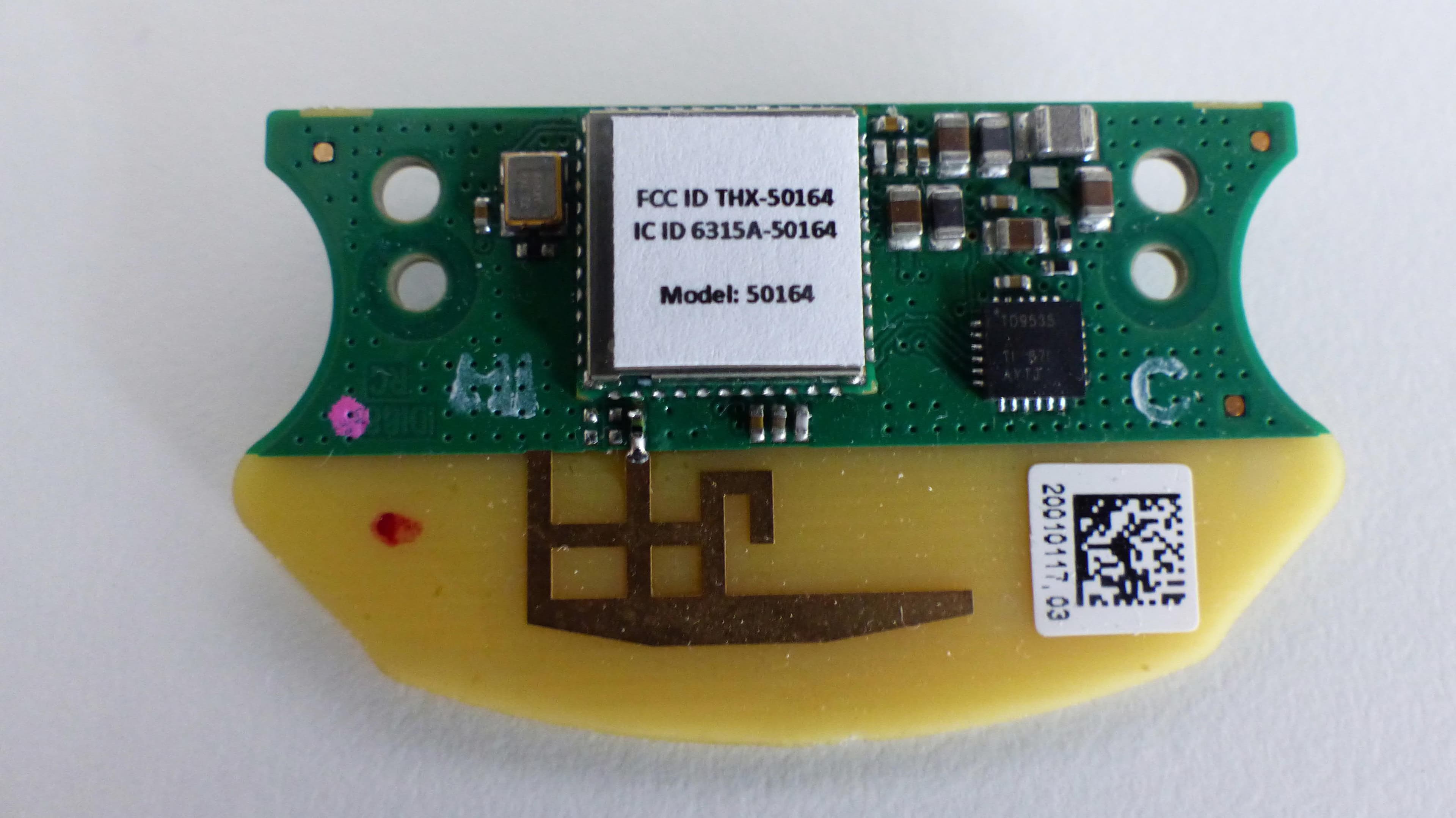
TXH-50164
Sep 21, 2020Wireless Module 50164
Equipment Class
DSS - Part 15 Spread Spectrum Transmitter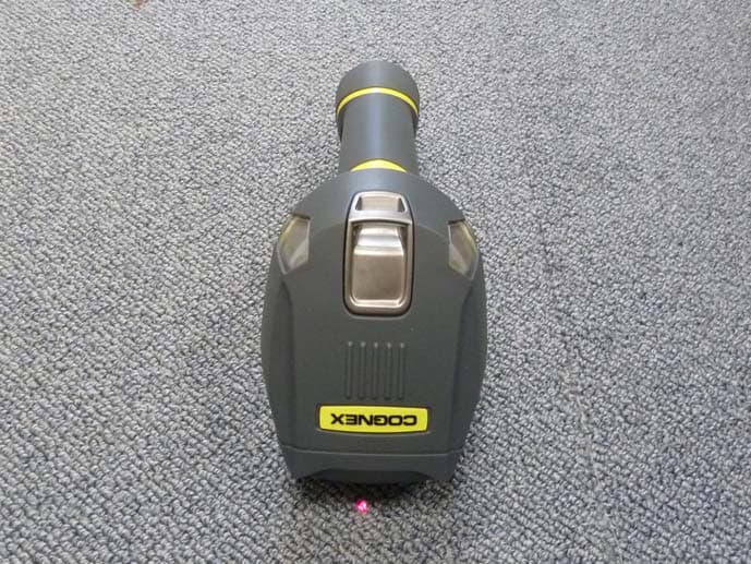
TXH-DM8000
Dec 18, 2011Barcode Scanner
Equipment Class
DTS - Digital Transmission System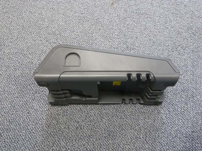
TXH-IBASE
Dec 18, 2011Bar code scanner base station
Equipment Class
DTS - Digital Transmission System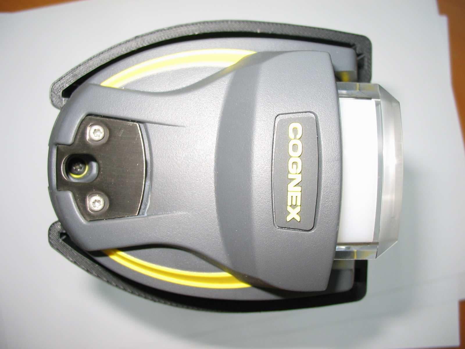
TXH-DM7550
Feb 06, 2006Handheld Reader for Industrial ID
Equipment Class
DSS - Part 15 Spread Spectrum Transmitter