TXH-DM8000Barcode Scanner
Cognex Germany Aachen GmbH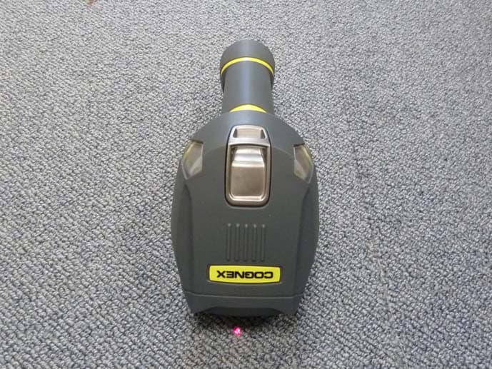
Click to zoom
Application Details
- Equipment Class
- DTS - Digital Transmission System
- Date of Grant
- Dec 18, 2011
- Application Purpose
- Original Equipment
- Date of Application
- Dec 18, 2011
- Equipment Note
- Barcode Scanner
- Frequency Range
- 2412.00000000 - 2462.00000000
- Company
- Cognex Germany Aachen GmbH
- Country
- Germany
Documents & Files
Document Text
Text extracted from the exhibit documents filed with the FCC. Open a document above to read the original.
Users Manual
COGNEX ® DataMan ® 8000 Series Quick Reference Guide ii DataMan 8000 Quick Reference GuideDataMan 8000 Quick Reference Guide iii Getting Started About DataMan 8000 • DataMan 8000 Accessories • Physical Layout of the Reader and the Base Station Page 4 1 DataMan 8000 Software Overview of Setting Up the Reader • Install DataMan 8000 Software • Start the Setup Tool • Use the Setup Tool Menu Bar Page 10 2 Connection Options Connecting through Ethernet • Troubleshooting an Ethernet Connection • Connecting through RS-232 • Keyboard Emulation • Connecting through USB 3 Using DataMan 8000 Series Wireless Readers Connecting to a Wireless DataMan 8000 • Base Station Routing Capabilities • Buffering Data • Charging • Changing Batteries 4 Industrial Protocols, Compliance Information, Warnings and Notices Industrial Protocols • DataMan 8000 Reader and Base Station Specifications • Laser Information • Agency Compliance Statements 6 Reading Codes with the DataMan 8000 Field of View and Reading Distances • Trigger Types 5 Page 16 Page 26 Page 41 Page 45 ii DataMan 8000 Quick Reference Guide Ethernet RS-232 USB Wireless 4 DataMan 8000 Quick Reference GuideDataMan 8000 Quick Reference Guide 5 About DataMan 8000 The DataMan 8000 series of readers offers the industry’s most advanced technology for reading 1D and 2D codes regardless of size, quality, printing method or surface, and is the only handheld ID reader that offers Industrial Ethernet communication and liquid lens technology. The DataMan 8000 series is available in two models, each with patented 1DMax and 2DMax algorithms, liquid lens technology, and future-proof modular communication slide-ins with optional Industrial Ethernet capability. The DataMan 8500 readers use Cognex’s patented UltraLight® technology for superior image formation on any mark type and surface. UltraLight illumination provides dark field, bright field and diffuse lighting all in one electronically controlled light. The DataMan 8100 readers feature integrated bright field illumination ideal for applications that require superior performance without specialty lighting. Both models are available with the following communication options: An intelligent base station is also provided when the DataMan 8000 reader uses the wireless communication module. The base station acts as a router between the reader and your computer or network. POE Adapter CPS-AC-POE1A-xx Serial/USB slide-in DMCM-SERIALM-00 Ethernet slide-in DMCM-ENETM-00 Wireless slide-in DMCM-WLESSM-00 Intelligent Base Station DMA-IBASE-00 Wall Mount DMA-WALL-8000-00 Power Supply for base station DMA-24VPWR-xx Power Supply for reader DM100-PWR-00 POE Adapter CPS-24V-POE1 POE Adapter CPS-24V-POE4 Battery for the wireless reader DMA-HHBATTERY-00 Stand DM-STAND-00 RS-232 coiled cable for reader, 2.5 m DM8000-RS232-02 RS-232 coiled cable for reader, 5 m DM8000-RS232-05 USB cable, 2.5 m DM8500-USB-02 USB coiled cable, 2.5 m DM8000-USBC-02 Ethernet cable, 5 m DM8000-ECABLE-05 Ethernet cable, 30 m DM8000-ECABLE-30 PS/2 adapter cable DM700-PS2-00 DataMan 8000 Reader Cables DataMan Base Station Cables RS-232 cable for base station, 5 m DMA-RS232-05 • USB cable for base station: Use any standard USB-A to USB-B 2.0 cable up to 3 meters • Ethernet cable for base station: Use any standard CAT5/5e, SF/FTP or S/FTP cable Ethernet cable, 2.5 m DM8000-ECABLE-02 6 DataMan 8000 Quick Reference GuideDataMan 8000 Quick Reference Guide 7 DataMan 8000 Accessories DataMan 8000 Accessories: Cables Laser aimer UltraLight (DataMan 8500 only) Lanyard hook Indicator Light Trigger (press and hold to read) Communication module Connection point with the reader: • pairing reader and base station • non-wireless communication • charging RS-232 USB Ethernet (with optional Class 3 PoE power) power plug (24V, max. 13W) spare battery charger status indicator base station status indicators spare battery charger Communication module insertion point 8 DataMan 8000 Quick Reference GuideDataMan 8000 Quick Reference Guide 9 Physical Layout of the Reader LASER LIGHT, DO NOT STARE INTO BEAM Physical Layout of the Base Station To be able to connect to your reader or base station on your computer, you must perform the following steps: 1. Install the Setup Tool on your computer. 2. Select the connection type: Ethernet, Serial, or USB. 3. Connect the appropriate cabling. 4. Power on your device(s). Ethernet RS-232 USB 10 DataMan 8000 Quick Reference GuideDataMan 8000 Quick Reference Guide 11 Overview of Setting Up the Reader RS-232/USB connection Install DataMan 8000 Software 1. Check the DataMan Release Notes for a full list of system requirements. 2. Insert CD-ROM and follow the on-screen prompts. 3. Connect the DataMan 8000 to your PC. 4. Launch the Setup Tool and click Refresh. The reader or the base station appears under COM ports or Network devices. 5. Select a COM port or a Network devices listing and click Connect. Ethernet connection “DM8_00” with last 6 characters of MAC address, printed on back of the reader or the base station 12 DataMan 8000 Quick Reference GuideDataMan 8000 Quick Reference Guide 13 Latest imageContext based help Connection status/Signal strength Battery level indicator Start the Setup Tool Connect the reader to the Setup Tool to configure it with the type of symbologies it will decode as well as other parameters, such as the type of trigger it will use and the format of the results it will generate. Alternatively, configure your reader by scanning the appropriate reader configuration code from the Reader Configuration Codes document, available through the Windows Start menu. Trigger button Read history Quick Setup Configure your reader in a few basic steps Connect to Reader Establish a connection to the reader Results Display View results Light and Imager Settings/ UltraLight Settings Choose a trigger type and other acquisition parameters System Settings Configure visual and audio feedback, trigger and output actions Use the Edit menu for standard…
Text truncated - open the document above for the full version.
Cover Letter(s)
1 Cognex Corporation One Vision Drive Natick, MA 01760-2059 (508) 650-3000 fax (508) 650-3333 www.cognex.com CONFIDENTIALITY REQUEST for Certification Service in USA Federal Communication Commission Equipment Authorization Division, Application Processing Branch 7435 Oakland Mills Road Columbia, MD 21048 December 8, 2011 TO WHOM IT MAY CONCERN Pursuant to Paragraphs §0.457 and 0.459 of the Commission’s Rules (47 C.F.R.) and Section §552(b)(4) of the Freedom of Information Act, we requests confidentiality for the following products: FCC ID Model name TXH-DM8000 DMR-8000 (or DataMan 8000) For the product stated above, we request permanent confidentiality for exhibits which contain Operational Description, Block Diagram, Schematics, Parts Lists or Tune Up Information. The above exhibits contain our trade secrets and proprietary information that could be of benefit to our competitors. If you have any questions, please feel free to contact me at the address shown below. Sincerely, Name: Guido Schuetzeichel Company: Cognex Ltd. Address: Vaalser Strasse 259, 52074 Aachen, Germany Phone: +49 241 17301426 Fax: +49 241 17301444 Email: [email protected]
External Photos
1 Cognex Corporation One Vision Drive Natick, MA 01760-2059 (508) 650-3000 fax (508) 650-3333 www.cognex.com External photos: top side bottom side 2 Cognex Corporation One Vision Drive Natick, MA 01760-2059 (508) 650-3000 fax (508) 650-3333 www.cognex.com side view
ID Label/Location Info
1 Cognex Corporation One Vision Drive Natick, MA 01760-2059 (508) 650-3000 fax (508) 650-3333 www.cognex.com ID Label/Label Location: Two labels will be permanently on the DM8000: Label 1 Label 2 2 Cognex Corporation One Vision Drive Natick, MA 01760-2059 (508) 650-3000 fax (508) 650-3333 www.cognex.com Label location ID label
Internal Photos
1 Cognex Corporation One Vision Drive Natick, MA 01760-2059 (508) 650-3000 fax (508) 650-3333 www.cognex.com Internal Photos: top side Antenna WiFi module 2 Cognex Corporation One Vision Drive Natick, MA 01760-2059 (508) 650-3000 fax (508) 650-3333 www.cognex.com bottom side
RF Exposure Info
Page 1 of 29 TEST REPORT Test Report No.: 1-3933/11-01-06 Testing Laboratory Applicant CETECOM ICT Services GmbH Untertürkheimer Straße 6 – 10 66117 Saarbrücken/Germany Phone: + 49 681 5 98 - 0 Fax: + 49 681 5 98 - 9075 Internet: http://www.cetecom.com e-mail: [email protected] Accredited Test Laboratory: The testing laboratory (area of testing) is accredited according to DIN EN ISO/IEC 17025 (2005) by the Deutsche Akkreditierungsstelle GmbH (DAkkS) The accreditation is valid for the scope of testing procedures as stated in the accreditation certificate with the registration number: D-PL-12076-01-01 Cognex Vaalser Straße 259 52074 Aachen/GERMANY Phone: --- Contact: Guido Schützeichel e-mail: [email protected] Phone: +49 241 173014 Fax: +49 241 1730144426 Manufacturer Cognex Vaalser Straße 259 52074 Aachen/GERMANY Test Standard/s IEEE 1528-2003 Recommended Practice for Determining the Peak Spatial-Average Specific Absorption Rate (SAR)in the Human Head from Wireless Communications Devices: Measurement Techniques OET Bulletin 65 Supplement C Evaluating Compliance with FCC Guidelines for Human Exposure to Radiofrequency Electromagnetic Fields RSS-102 Issue 4 Radio Frequency Exposure Compliance of Radiocommunication Apparatus (All Frequency Bands) For further applied test standards please refer to section 3 of this test report. Test Item Kind of test item: Barcode Scanner Device type: handheld device Model name: DataMan 8000 S/N serial number: 1A1132XN005051 FCC-ID: TXH-DM8000 IC: 6315A-DM8000 Hardware status: V4.2_a2 Software status: V4.2_a2 Frequency: see technical details Antenna: integrated antenna Battery option: Rechargeable Li-ion Battery 3.7V / 2200mAh Accessories: --- Test sample status: identical prototype Exposure category: Industrial rang / Controlled Environment Occupational This test report is electronically signed and valid without handwriting signature. For verification of the electronic signatures, the public keys can be requested at the testing laboratory. Test Report authorised: Test performed: Thomas Vogler Oleksandr Hnatovskiy Senior Testing Manager Testing Manager Test report no.: 1-3933/11-01-06 Page 2 of 29 1 Table of contents 1 Table of contents ....................................................................................................................................... 2 2 General information .................................................................................................................................. 3 2.1 Notes and disclaimer ..................................................................................................................... 3 2.2 Application details ......................................................................................................................... 3 2.3 Statement of compliance ............................................................................................................... 3 2.4 Technical details............................................................................................................................. 4 3 Test standard/s: ......................................................................................................................................... 5 3.1 RF exposure limits ......................................................................................................................... 5 4 Summary of Measurement Results ......................................................................................................... 6 5 Test Environment ...................................................................................................................................... 6 6 Test Set-up ................................................................................................................................................. 7 6.1 Measurement system ..................................................................................................................... 7 6.1.1 System Description ................................................................................................................ 7 6.1.2 Test environment ................................................................................................................... 8 6.1.3 Probe description ................................................................................................................... 8 6.1.4 Phantom description .............................................................................................................. 9 6.1.5 Device holder description ...................................................................................................... 9 6.1.6 Scanning procedure ............................................................................................................ 10 6.1.7 Spatial Peak SAR Evaluation .............................................................................................. 11 6.1.8 Data Storage and Evaluation............................................................................................... 12 6.1.9 Tissue simulating liquids: dielectric properties .................................................................... 14 6.1.10 Tissue simulating liquids: parameters ................................................................................. 14 6.1.11 Measurement uncertainty evaluation for SAR test .............................................................. 15 6.1.12 Measurement uncertainty evaluation for system validation ................................................ 16 6.1.13 System validation ................................................................................................................ 17 6.1.14 Validation procedure ............................................................................................................ 17 7 Detailed Test Results ....................................................................................................…
Text truncated - open the document above for the full version.
RF Exposure Info
Page 1 of 7 Annex C Photo documentation Appendix to Test Report No.: 1-3933/11-01-06 Testing Laboratory CETECOM ICT Services GmbH Untertürkheimer Straße 6 – 10 66117 Saarbrücken/Germany Phone: + 49 681 5 98 - 0 Fax: + 49 681 5 98 - 9075 Internet: http://www.cetecom.com e-mail: [email protected] Accredited Test Laboratory: The testing laboratory (area of testing) is accredited according to DIN EN ISO/IEC 17025 (2005) by the Deutsche Akkreditierungsstelle GmbH (DAkkS) The accreditation is valid for the scope of testing procedures as stated in the accreditation certificate with the registration number: D-PL-12076-01-01 Annex C to Test report no.: 1-3933/11-01-06 Page 2 of 7 Photo 1: Measurement System DASY 4 Photo 2: DUT - rear view Annex C to Test report no.: 1-3933/11-01-06 Page 3 of 7 Photo 3: DUT - side view Photo 4: DUT - front view Annex C to Test report no.: 1-3933/11-01-06 Page 4 of 7 Photo 5: DUT (label) Photo 6: The battery Annex C to Test report no.: 1-3933/11-01-06 Page 5 of 7 Photo 7: Test position rear side Photo 8: Test position front side Annex C to Test report no.: 1-3933/11-01-06 Page 6 of 7 Photo 9: Test position left side Photo 10: Test position right side Annex C to Test report no.: 1-3933/11-01-06 Page 7 of 7 Photo 11: Test position top side
Test Report
2011-12-13 Page 1 of 72 TEST REPORT Test report no.: 1-3933/11-01-03 Testing laboratory Applicant CETECOM ICT Services GmbH Untertuerkheimer Strasse 6 – 10 66117 Saarbruecken / Germany Phone: + 49 681 5 98 - 0 Fax: + 49 681 5 98 - 9075 Internet: http://www.cetecom.com e-mail: [email protected] Accredited Testing Laboratory: The testing laboratory (area of testing) is accredited according to DIN EN ISO/IEC 17025 (2005) by the Deutsche Akkreditierungsstelle GmbH (DAkkS) The accreditation is valid for the scope of testing procedures as stated in the accreditation certificate with the registration number: D-PL-12076-01-01 Area of Testing: Radio/Satellite Communications Cognex Vaalser Straße 259 52074 Aachen / GERMANY Phone: +49 241 17301426 Fax: +49 241 17301444 Contact: Guido Schuetzeichel e-mail: [email protected] Phone: +49 241 17301426 Manufacturer Cognex Vaalser Straße 259 52074 Aachen / GERMANY Test standard/s 47 CFR Part 15 Title 47 of the Code of Federal Regulations; Chapter I Part 15 - Radio frequency devices RSS - 210 Issue 8 Spectrum Management and Telecommunications - Radio Standards Specification Low-power Licence-exempt Radiocommunication Devices (All Frequency Bands): Category I Equipment For further applied test standards please refer to section 3 of this test report. Test Item Kind of test item: Barcode Scanner Model name: DM8500 FCC ID: TXH-DM8000 IC: 6315A-DM8000 Frequency [MHz]: ISM-band 2400 MHz – 2483.5 MHz (Lowest Channel 2412 MHz – Highest Channel 2462 MHz) Technology tested: WLAN Antenna: Integrated Antenna Power Supply: 3.70 V DC by Li-Ion battery Temperature Range: -20°C to +55 °C This test report is electronically signed and valid without handwriting signature. For verification of the electronic signatures, the public keys can be requested at the testing laboratory. Test report authorised: Test performed: Marco Bertolino Stefan Bös Testing Manager Senior Testing Manager Test report no.: 1-3933/11-01-03 2011-12-13 Page 2 of 72 1 Table of contents 1 Table of contents ............................................................................................................................................ 2 2 General information ....................................................................................................................................... 3 2.1 Notes and disclaimer .......................................................................................................................... 3 2.2 Application details ............................................................................................................................... 3 3 Test standard/s ............................................................................................................................................... 3 4 Test environment ............................................................................................................................................ 4 5 Test item .......................................................................................................................................................... 4 6 Test laboratories sub-contracted ................................................................................................................. 4 7 Summary of measurement results ............................................................................................................... 5 8 RF measurements .......................................................................................................................................... 6 8.1 Description of test setup .................................................................................................................... 6 8.1.1 Radiated measurements............................................................................................................. 6 8.1.2 Conducted measurements.......................................................................................................... 7 8.2 Additional comments .......................................................................................................................... 7 8.3 RSP100 test report cover sheet / performance test data ................................................................ 8 9 Measurement results ...................................................................................................................................... 9 9.1 Maximum output power (conducted) ................................................................................................ 9 9.2 Antenna gain ........................................................................................................................................ 9 9.3 Maximum output power ...................................................................................................................... 9 9.4 Power spectral density ..................................................................................................................... 11 9.5 Spectrum bandwidth of a FHSS system – 6 dB bandwidth .......................................................... 11 9.6 Spectrum bandwidth of a FHSS system – 20 dB bandwidth ........................................................ 11 9.7 Band edge compliance conducted .................................................................................................. 11 9.8 Band edge compliance radiated ...................................................................................................... 12 9.9 TX spurious emissions conducted .................................................................................................. 17 9.10 TX spurious emissions radiated................................................................................................... 18 9.11 RX spurious emissions radiated .................................................................................................. 44 9.12 TX spurious emissions radiat…
Text truncated - open the document above for the full version.
Test Setup Photos
Test report no.: 1-3933/11-01-03 2011-12-13 Page 57 of 72 Annex A Photographs of the test setup Photo documentation: Photo 1: Photo 2:
Contact Information
Applicant
Simon Juenger(Compliance Engineer)
Test Firm
Cetecom ICT Services GmbHRalf Hoehn
Technical Specifications
| # | Rule Parts | Frequency Range | Power Output |
|---|---|---|---|
| 1 | 15C | 2.41 GHz - 2.46 GHz | 30.00 mW |
Other Applications from Cognex Germany Aachen GmbH

TXH-50165
Jan 17, 202250165
Equipment Class
DTS - Digital Transmission System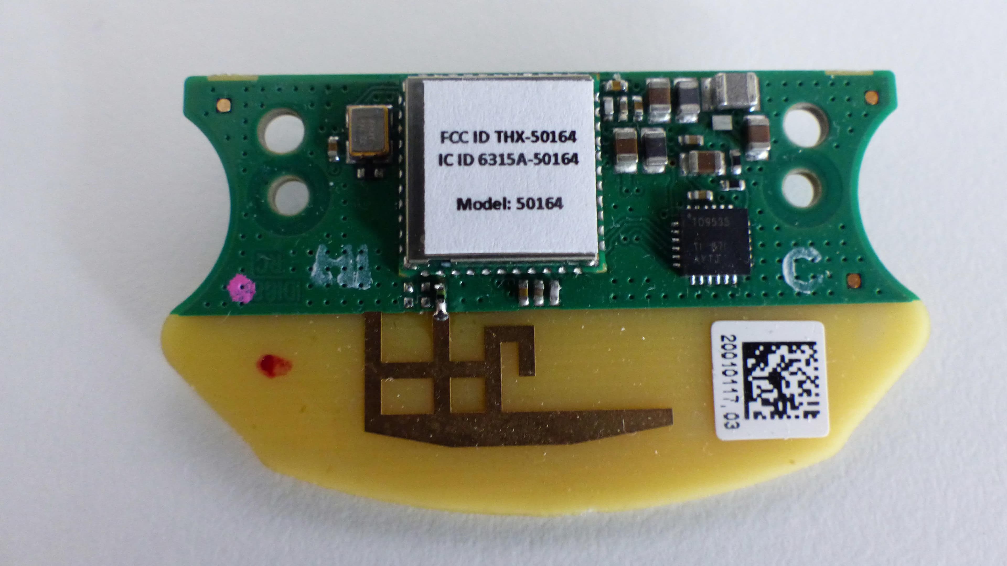
TXH-50164
Sep 21, 2020Wireless Module 50164
Equipment Class
DSS - Part 15 Spread Spectrum Transmitter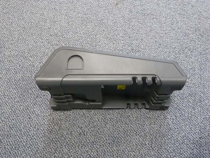
TXH-IBASE
Dec 18, 2011Bar code scanner base station
Equipment Class
DTS - Digital Transmission System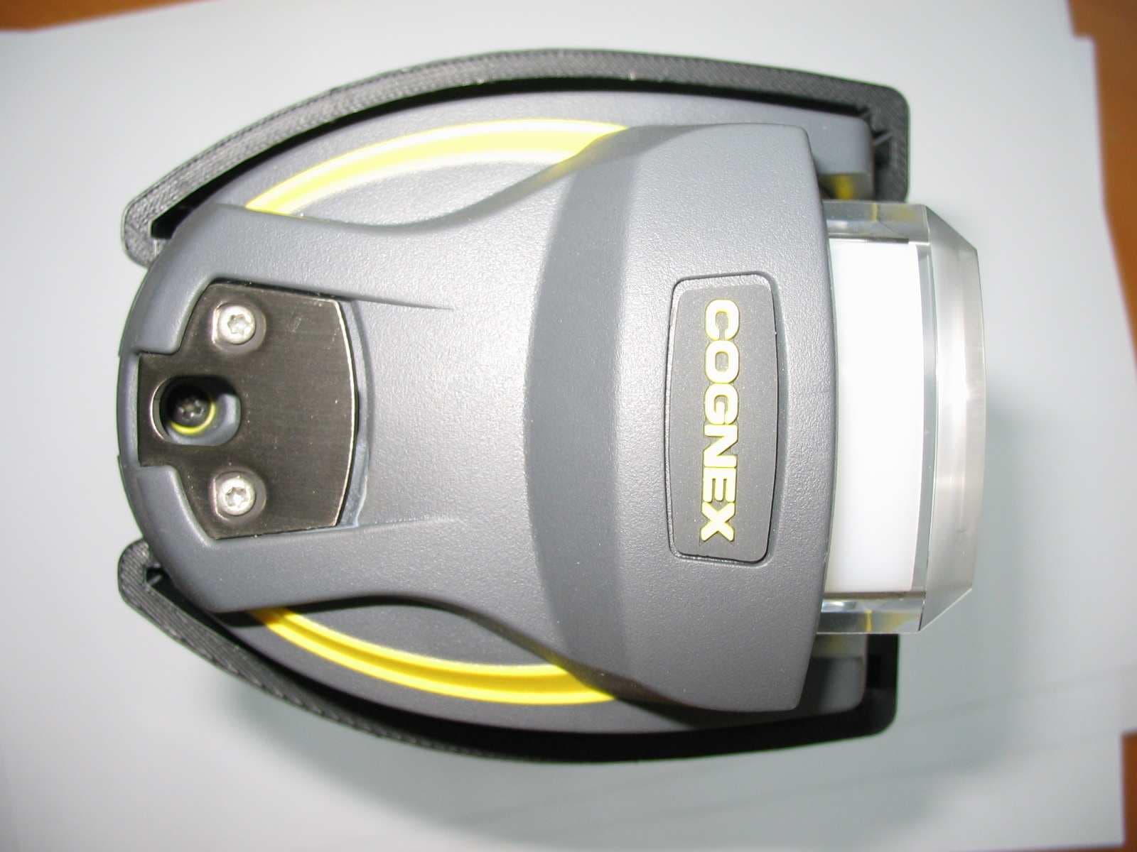
TXH-DM7550
Feb 06, 2006Handheld Reader for Industrial ID
Equipment Class
DSS - Part 15 Spread Spectrum Transmitter