TZIUX598Bluetooth & WIFI & 5G WIFI VR All-in-One HMD
Arts Electronics Co., Ltd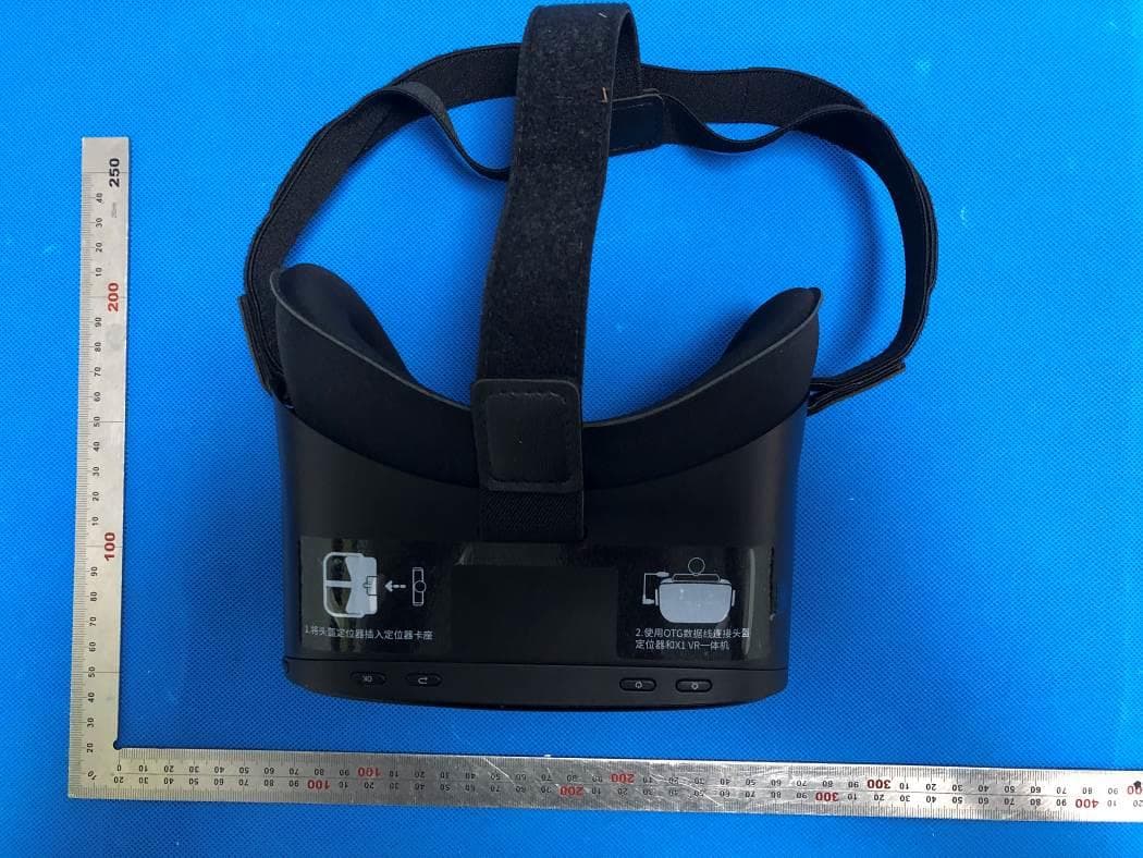
Click to zoom
Application Details
- Equipment Class
- DTS - Digital Transmission System
- Date of Grant
- Sep 15, 2020
- Application Purpose
- Original Equipment
- Date of Application
- Sep 15, 2020
- Equipment Note
- Bluetooth & WIFI & 5G WIFI VR All-in-One HMD
- Frequency Range
- 2412.00000000 - 2462.00000000
- Company
- Arts Electronics Co., Ltd
- Country
- China
Documents & Files
Document Text
Text extracted from the exhibit documents filed with the FCC. Open a document above to read the original.
Users Manual
ARTS UX598C VR All-in-One User Manual Dear users Thank you for using our ARTS UX598C VR all-in-one machine. It is a virtual reality display device that will bring you an unprecedented visual experience. In order for you to operate this product as quickly and easily as possible, it is recommended that you read the user manual carefully before use. 1、Matters needing attention In order to avoid damage to this product, please observe the following: Do not place the product under high humidity, frequent vibration, persistent high temperature (such as under sunlight) or other adverse conditions, otherwise the product may be deformed and damaged. Do not drop, press, bend or use heavy objects to press the product. There are precision optical components in the product, so avoid hitting and scratching the mirror surface when using. Please kee p the window lens clean and clean. You can quickly wipe it with a soft lens cleaning cloth, neutral paper, alcohol cleaner, etc. If there is a problem with the product, please carry out after -sales treatment through professional maintenance channels. Please do not try to disassemble the product yourself. Do not use the device where wireless devices are prohibited. Please use original accessories such as power adapter. If you encounter a software card machine, you can press and hold the power button for 10 seconds to restart the device. 2、Spec Model: UX598C Operating system: Android 8.1 Central processor: Qualcomm XR1 octa -core Graphics processor: Adreno 615 Running memory: 3G LPDDR3 Storage memory: 32G EMMC Optical lens: Fresnel and aspheric combined lens FOV100 degrees Display: 5.5 inches, Fast LCD, 2560 * 1440 (optional 4k Fast LCD), 75HZ Weight: 385g (including headband) Battery: Lithium polymer battery, 4000Mah, support 4H to play movies Charging input: DC 5V / 3A Interf ace: TypeC, TF card slot, standard 3.5mm headphone jack Audio output: external headphone output, built -in dual speakers Camera (optional): 13 million, 60 frames Support Wi -Fi: 2.4G / 5G Support Bluetooth: Bluetooth 5.0 Sensors: gyroscope, geomagn etometer, gravity sensor, distance sensor Operating temperature: -5 to 40 degrees Supported languages: Simplified Chinese, English, etc. Certification: CCC / CE / FCC / RoHS 3、Wearing instructions Before wearing it for the first time, please remove the protective film of the optical lens to avoid affecting the viewing effect. Before wearing, press the power button to ensure that the device is turned on. Open the elastic band, adjust the left, right, a nd middle elastic bands respectively, so that the headset matches your head shape, and finally move the device to achieve the best viewing effect. 4、Appearance 4.1、Key Instruction Power button: short press to realize sleep / wake function Press and hold for 10 seconds to realize the forced shutdown function Volume ➕ key: short press to increase volume Volume ➖ key: short press to realize volume down function Confirm key: short press to realize the confirmation function Back key: short press to rea lize the return function MENU key: short press to realize the MENU function, such as recalling volume, brightness adjustment and other optional functions Up / Down / Left / Right key: Short press to realize Up / Down / Left / Right function 4.2. Interface Description Support external 3.5mm standard headphones Support external TF card Support TypeC interface USB function Support MIC function 4.3. Description of parts Built-in dual stereo speakers on the left and right side of the device With high-definition professional optical lenses Equipped with high -soft skin-friendly eye mask sponge and headwear to increase wearing comfort 5. Product function description Main page The main page includes settings, media player, application store, all application software, power display, time display, access device display, wireless network status. Settings The setting options include five parts: wireless network connection, Bluetooth, universal, system, and peripherals. Wireless network Select the corresponding wireless network to disconnect and cancel the saved password. Bluetooth After turning on Bluetooth, it automatically searches for Bluetooth devices, and users choose to connect to Bluetooth devices as needed. General options Through general options, adjust the screen brightness, volume size, select language, select theme, sleep time, and change the time zone. System Through system options, update the system, restore factory settings and view device information Peripherals Under this option, you can view and manage the peripherals connected to the VR all-in-one, such as the remote control and game gun. Media playback The player contains two parts: local video and online video playback. App store Users can download games and applications in the application market by connecting to Wi-Fi. All applications All games and applications installed by the user will be displayed in all applications, and the user can manage and uninstall the installed applications. Please select the interface that needs to be opened according to the instruction map path according to the usage requirements. 6、Packing List UX598C VR HMD *1 Adaptor *1 Type C Cable *1 User Manual *1 7、Security Information This safety information contains important content applicable to this product. Before using the device, to ensure safe and correct use of the device, please refer to all safety information to ensure the normal use of the device, while avoiding danger or abnormal use, affecting the experience. Saf ety warning * Some people may experience severe dizziness, vomiting, palpitations and other symptoms when using VR devices. If any similar situation occurs, please suspend the use of VR devices and consult a doctor before using them again. * Children under 12 years of age should be used under adult supervision to a…
Text truncated - open the document above for the full version.
Cover Letter(s)
Arts Electronics Co., Ltd. NO. 1, SHANGXING LU, SHANGJIAO COMMUNITY, CHANGAN TOWN, DONGGUAN CITY, GUANGDONG PROVINCE, China Aug. 06, 2020 Office of Engineering Technology Federal Communications Commission 7435 Oakland Mills Road Columbia, MD 21046 USA Subject: Explanation of differences between product types FCC ID: TZIUX598 Models: UX598C, CVR-255, UX598 To Whom It May Concern: We, The Arts Electronics Co., Ltd. hereby declare that the model: CVR-255, UX598 is identical with the model: UX598C, except the following difference: UX598C Model: Face board with camera; 5.5-inch 2560 x 1440 resolution display. And it corresponding to the brand ARTS. For CVR-255 Model: It is consistent with UX598C except that the appearance color, model name and brand names are different. And it corresponding to the brand ClassVR. For UX598 Model: Face board without camera. It is consistent with UX598C. Except for the different above, no other modification is performed. Sincerely, Arts Electronics Co., Ltd. Signature: [SH Lee, Safety Engineer]
Cover Letter(s)
Arts Electronics Co., Ltd. NO. 1, SHANGXING LU, SHANGJIAO COMMUNITY, CHANGAN TOWN, DONGGUAN CITY, GUANGDONG PROVINCE, China Office of Engineering Technology Federal Communications Commission 7435 Oakland Mills Road Columbia, MD 21046 USA Date: Aug. 06, 2020 Subject; Request for Confidentiality FCC ID: TZIUX598 To Whom It May Concern, Pursuant to the provisions of the Commission’s rules Title 47 Sections §0.457 and §0.459, we are requesting the Commission to withhold the following attachment(s) as confidential documents from public disclosure indefinitely. These documents contain detailed system and equipment descriptions and are considered as proprietary information in operation of the equipment. The public disclosure of these documents might be harmful to our company and would give competitors an unfair advantage in the market. Schematic Diagram Block Diagram Operational Description FCC Software Security Description It is our understanding that all measurement test reports, FCC ID label format and correspondence during the certification review process cannot be granted as confidential documents and this information will be available for public review once the grant of equipment authorization is issued. Sincerely, Signature: Name: SH Lee Title: Safety Engineer
Cover Letter(s)
Arts Electronics Co., Ltd. NO. 1, SHANGXING LU, SHANGJIAO COMMUNITY, CHANGAN TOWN, DONGGUAN CITY, GUANGDONG PROVINCE, China UNII Declaration Letter We have declared below featured for FCC equipment authorization, device FCC ID: TZIUX598 (1) DFS Device -- Master, Client with Radar detection capability , Client without radar detection capability, N/A (2) Active / Passive Scanning , adhoc mode access point capability Frequency Band (MHz) Active Scanning (the device can transmit a probe (beacon)) passive scanning (where the device is can listen only with no probes) Ad Hoc Mode capability Access point capability 2412 – 2462 MHz Yes, No Yes, No Yes, No Yes, No 2422 – 2452 MHz Yes, No Yes, No Yes, No Yes, No 5745 – 5825 MHz Yes, No Yes, No Yes, No Yes, No 5755 – 5795 MHz Yes, No Yes, No Yes, No Yes, No 5180 – 5240 MHz Yes, No Yes, No Yes, No Yes, No 5190 – 5230 MHz Yes, No Yes, No Yes, No Yes, No (3) Country code selection ability - Yes , No If no, pls explain how was implemented : (4) Meet 15.202 requirement - Yes , No , pls check below : A master device is defined as a device operating in a mode in which it has the capability to transmit without receiving an enabling signal. In this mode it is able to select a channel and initiate a network by sending enabling signals to other devices A client device is defined as a device operating in a mode in which the transmissions of the device are under control of the master. A device in client mode is not able to initiate a network. (5) For client devices that have software configuration control to operate in different modes (active scanning in some and passive scanning in others) in different bands (devices with multiple equipment classes or those that operate on non-DFS frequencies) or modular devices which configure the modes of operations through software, the application must provide software and operations description on how the software and / or hardware is implemented to ensure that proper operations modes can not be modified by end user or an installer. Apply , No Apply , (If apply , pls help to provide explanation on how it was implement (By hardware or software , and how software was controlled) If you have any questions, please feel free to contact me at the address shown below. Yours sincerely, Signatory Name: SH Lee Title: Safety Engineer
External Photos
External Photos ALL VIEW OF EUT UX598C& CVR-255 UX598 Test model: UX598C TOTAL VIEW OF EUT TOP VIEW OF EUT BOTTOM VIEW OF EUT FRONT VIEW OF EUT BACK VIEW OF EUT LEFT VIEW OF EUT RIGHT VIEW OF EUT VIEW OF EUT(PORT) VIEW OF ADAPTER Series model: CVR-255 TOTAL VIEW OF EUT TOP VIEW OF EUT BOTTOM VIEW OF EUT FRONT VIEW OF EUT BACK VIEW OF EUT LEFT VIEW OF EUT RIGHT VIEW OF EUT VIEW OF EUT(PORT) Series model: UX598 (White color) TOTAL VIEW OF EUT TOP VIEW OF EUT BOTTOM VIEW OF EUT FRONT VIEW OF EUT BACK VIEW OF EUT LEFT VIEW OF EUT RIGHT VIEW OF EUT VIEW OF EUT(PORT) Series model: UX598 (Black color) TOTAL VIEW OF EUT TOP VIEW OF EUT BOTTOM VIEW OF EUT FRONT VIEW OF EUT BACK VIEW OF EUT LEFT VIEW OF EUT RIGHT VIEW OF EUT
ID Label/Location Info
FCC ID and IC Label Location 20mm*20mm FCC ID: TZIUX598 IC: 7234A-UX598 HVIN: UX598C 20mm*20mm FCC ID: TZIUX598 IC: 7234A-UX598 HVIN: CVR-255 20mm*20mm FCC ID: TZIUX598 IC: 7234A-UX598 HVIN: UX598
Internal Photos
Internal Photos Test model: UX598C OPEN VIEW OF EUT-1 OPEN VIEW OF EUT-2 OPEN VIEW OF EUT-3 OPEN VIEW OF EUT-4 BT/WIFI Antenna 0 WIFI Antenna 1 OPEN VIEW OF EUT-4 OPEN VIEW OF EUT-5 INTERNAL VIEW-1 OF EUT INTERNAL VIEW-2 OF EUT INTERNAL VIEW-3 OF EUT INTERNAL VIEW-4 OF EUT INTERNAL VIEW-5 OF EUT INTERNAL VIEW-6 OF EUT INTERNAL VIEW-7 OF EUT INTERNAL VIEW-8 OF EUT INTERNAL VIEW-9 OF EUT VIEW OF BATTERY Series model: CVR-255 OPEN VIEW OF EUT-1 OPEN VIEW OF EUT-2 OPEN VIEW OF EUT-3 INTERNAL VIEW-1 OF EUT INTERNAL VIEW-2 OF EUT INTERNAL VIEW-3 OF EUT INTERNAL VIEW-4 OF EUT INTERNAL VIEW-5 OF EUT INTERNAL VIEW-6 OF EUT INTERNAL VIEW-7 OF EUT INTERNAL VIEW-8 OF EUT INTERNAL VIEW-9 OF EUT INTERNAL VIEW-10 OF EUT INTERNAL VIEW-11 OF EUT
Internal Photos
VIEW OF BATTERY Series model: UX598 (White color) OPEN VIEW OF EUT-1 OPEN VIEW OF EUT-2 INTERNAL VIEW-1 OF EUT INTERNAL VIEW-2 OF EUT INTERNAL VIEW-3 OF EUT INTERNAL VIEW-4 OF EUT INTERNAL VIEW-5 OF EUT INTERNAL VIEW-6 OF EUT INTERNAL VIEW-7 OF EUT INTERNAL VIEW-8 OF EUT VIEW OF BATTERY Series model: UX598 (Black color) OPEN VIEW OF EUT-1 OPEN VIEW OF EUT-2 OPEN VIEW OF EUT-3 OPEN VIEW OF EUT-4 BT/WIFI Antenna 0 WIFI Antenna 1 INTERNAL VIEW-1 OF EUT INTERNAL VIEW-2 OF EUT INTERNAL VIEW-3 OF EUT INTERNAL VIEW-4 OF EUT INTERNAL VIEW-5 OF EUT INTERNAL VIEW-6 OF EUT INTERNAL VIEW-7 OF EUT
RF Exposure Info
RF EXPOSURE EVALUATION 1. PRODUCT INFORMATION Product Description VR All-in-One HMD Model Name UX598C, CVR-255, UX598 FCC ID TZIUX598 2. EVALUATION METHOD According to KDB 447498 D01 cl. 4.3.1: a) For 100 MHz to 6 GHz and test separation distances ≤ 50 mm, the 1-g and 10-g SAR t est exclusion thresholds are determined by the following: [(max. power of channel, including tune-up tolerance, mW) / (min. test separation distanc e, mm)] • [√f(GHz)] ≤ 3.0 b) For 100 MHz to 6 GHz and test separation distances > 50 mm, the 1-g and 10-g SAR t est exclusion thresholds are determined by the following: 1) {[Power allowed at numeric threshold for 50 mm in step a)] + [(test separation distance – 50 mm)•(f(MHz)/150)]} mW, for 100 MHz to 1500 MHz 2) {[Power allowed at numeric threshold for 50 mm in step a)] + [(test separation distance – 50 mm)•10]} mW, for > 1500 MHz and ≤ 6 GHz 3. CALCULATION Take 2.4G WIFI as an example P t =14.14dBm=25.94mW The value of the Maximum output power P t is referred to the test report of the AGC03195200602FE05. The test separation distance of UX598C& CVR-255 is 65mm. The test separation distance of antenna0 is 30mm and antenna1 is 37mm for UX598. As long as antenna 0 can be exempted, antenna 1 can also be exempted. 65mm 37mm 30mm For UX598C and CVR-255, 2.4GHz WLAN SAR test exclusion threshold =(3.0*50mm)/[√2.412(GHz)]+[(65mm-50mm).10]=246.58mW>25.94mW, SAR evaluation for 2.4G WIFI are not required. For UX598C and CVR-255, 2.4GHz WLAN-MIMO SAR test exclusion threshold =(3.0*50mm)/[√2.412(GHz)]+[(65mm-50mm).10]=246.58mW>28.71mW. SAR evaluation for 2.4G WIFI-MIMO are not required. Similarly, the SAR exemption thresholds for the following frequency bands can be obtained. SAR test exclusion thresholds for UX598C and CVR-255 Mode Frequency(GHz) Maximum source-based time averaged conducted output power including tune-up tolerance (mW) SAR test exclusion thresholds (mW) for 1-g SAR Minimum separation distance (mm) Verdict BT 2.402-2.480 5.46 246.01 65 Exempt from SAR WLAN 2.412-2.462 25.94 246.58 65 Exempt from SAR U-NII-1 5.15-5.25 19.19 215.91 65 Exempt from SAR U-NII-2A 5.25-5.35 14.09 215.40 65 Exempt from SAR U-NII-2C 5.47-5.725 12.97 212.83 65 Exempt from SAR U-NII-3 5.725-5850 14.22 212.15 65 Exempt from SAR SAR test exclusion thresholds for UX598C and CVR-255 Mode Frequency(GHz) Maximum source-based time averaged conducted output power including tune-up tolerance (mW) SAR test exclusion thresholds (mW) for 1-g SAR Minimum separation distance (mm) Verdict WLAN-MIMO 2.412-2.462 28.71 246.58 65 Exempt from SAR U-NII-1-MIMO 5.15-5.25 20.00 215.91 65 Exempt from SAR U-NII-2A-MIMO 5.25-5.35 13.74 215.40 65 Exempt from SAR U-NII-2C-MIMO 5.47-5.725 12.30 212.83 65 Exempt from SAR U-NII-3-MIMO 5.725-5850 13.52 212.15 65 Exempt from SAR For UX598, 2.4GHz WLAN SAR test exclusion threshold =(3.0*30mm)/[√2.412(GHz)] =57.95mW>25.94mW, SAR evaluation for 2.4G WIFI are not required. For UX598, 2.4GHz WLAN-MIMO SAR test exclusion threshold =(3.0*30mm)/[√2.412(GHz)] =57.95mW>28.71mW, SAR evaluation for 2.4G WIFI-MIMO are not required. Similarly, the SAR exemption thresholds for the following frequency bands can be obtained. SAR test exclusion thresholds for UX598 Mode Frequency(GHz) Maximum source-based time averaged conducted output power including tune-up tolerance(mW) SAR test exclusion thresholds(mW) for 1-g SAR Minimum separation distance (mm) Verdict BT 2.402-2.480 5.46 57.60 30 Exempt from SAR WLAN 2.412-2.462 25.94 57.95 30 Exempt from SAR U-NII-1 5.15-5.25 19.19 39.54 30 Exempt from SAR U-NII-2A 5.25-5.35 14.09 39.24 30 Exempt from SAR U-NII-2C 5.47-5.725 12.97 37.70 30 Exempt from SAR U-NII-3 5.725-5850 14.22 37.29 30 Exempt from SAR SAR test exclusion thresholds for UX598 Mode Frequency(GHz) Maximum source-based time averaged conducted output power including tune-up tolerance(mW) SAR test exclusion thresholds(mW) for 1-g SAR Minimum separation distance (mm) Verdict WLAN-MIMO 2.412-2.462 28.71 57.95 30 Exempt from SAR U-NII-1-MIMO 5.15-5.25 20.00 39.54 30 Exempt from SAR U-NII-2A-MIMO 5.25-5.35 13.74 39.24 30 Exempt from SAR U-NII-2C-MIMO 5.47-5.725 12.30 37.70 30 Exempt from SAR U-NII-3-MIMO 5.725-5850 13.52 37.29 30 Exempt from SAR 4. CONCLUSION The SAR evaluation is not required.
Test Report
Page 1 of 90 Report No.: AGC03195200602FE05 FCC ID : TZIUX598 APPLICATION PURPOSE : Original Equipment PRODUCT DESIGNATION : VR All-in-One HMD BRAND NAME : ARTS, ClassVR MODEL NAME : UX598C, CVR-255, UX598 APPLICANT : Arts Electronics Co., Ltd. DATE OF ISSUE : Jul. 01, 2020 STANDARD(S) TEST PROCEDURE(S) : FCC Part 15.247 ANSI C63.10 REPORT VERSION : V1.0 Attestation of Global Compliance (Shenzhen) Co., Ltd CAUTION: This report shall not be reproduced except in full without the written permission of the test laboratory and shall not be quoted out of context. FCC Test Report Report No.: AGC03195200602FE05 Page 2 of 90 REPORT REVISE RECORD Report Version Revise Time Issued Date Valid Version Notes V1.0 / Jul. 01, 2020 Valid Initial Release Report No.: AGC03195200602FE05 Page 3 of 90 TABLE OF CONTENTS 1. VERIFICATION OF CONFORMITY .................................................................................................................. 5 2. GENERAL INFORMATION .............................................................................................................................. 6 2.1. PRODUCT DESCRIPTION ........................................................................................................................ 6 2.2. TABLE OF CARRIER FREQUENCYS ....................................................................................................... 7 2.3. IEEE 802.11N MODULATION SCHEME .................................................................................................... 8 2.4. RELATED SUBMITTAL(S) / GRANT (S) .................................................................................................... 8 2.5. TEST METHODOLOGY ............................................................................................................................. 8 2.6. SPECIAL ACCESSORIES ......................................................................................................................... 8 2.7. EQUIPMENT MODIFICATIONS ................................................................................................................. 8 2.8. ANTENNA REQUIREMENT ....................................................................................................................... 9 3. MEASUREMENT UNCERTAINTY ................................................................................................................. 10 4. DESCRIPTION OF TEST MODES ................................................................................................................. 11 5. SYSTEM TEST CONFIGURATION ................................................................................................................ 12 5.1. CONFIGURATION OF EUT SYSTEM ...................................................................................................... 12 5.2. EQUIPMENT USED IN EUT SYSTEM ..................................................................................................... 12 5.3. SUMMARY OF TEST RESULTS .............................................................................................................. 12 6. TEST FACILITY .............................................................................................................................................. 13 7. OUTPUT POWER ........................................................................................................................................... 14 7.1. MEASUREMENT PROCEDURE ............................................................................................................. 14 7.2. TEST SET-UP (BLOCK DIAGRAM OF CONFIGURATION) .................................................................... 14 7.3. LIMITS AND MEASUREMENT RESULT .................................................................................................. 15 8. 6 DB BANDWIDTH ......................................................................................................................................... 17 8.1. MEASUREMENT PROCEDURE ............................................................................................................. 17 8.2. TEST SET-UP (BLOCK DIAGRAM OF CONFIGURATION) .................................................................... 17 8.3. LIMITS AND MEASUREMENT RESULTS ............................................................................................... 18 9. CONDUCTED SPURIOUS EMISSION........................................................................................................... 26 Report No.: AGC03195200602FE05 Page 4 of 90 9.1. MEASUREMENT PROCEDURE ............................................................................................................. 26 9.2. TEST SET-UP (BLOCK DIAGRAM OF CONFIGURATION) .................................................................... 26 9.3. MEASUREMENT EQUIPMENT USEDJN ................................................................................................ 26 9.4. LIMITS AND MEASUREMENT RESULT .................................................................................................. 26 10. MAXIMUM CONDUCTED OUTPUT POWER SPECTRAL DENSITY ........................................................ 45 10.1 MEASUREMENT PROCEDURE ............................................................................................................ 45 10.2 TEST SET-UP (BLOCK DIAGRAM OF CONFIGURATION) ................................................................... 45 10.3 MEASUREMENT EQUIPMENT USED ................................................................................................... 45 10.4 LIMITS AND MEASUREMENT RESULT ................................................................................................. 45 11. RADIATED EMISSION ................................................................................................................................. 59 11.1. MEASUREMENT PROCEDURE..........................................................…
Text truncated - open the document above for the full version.
Test Report
Report No.: AGC03195200602FE05 Page 51 of 90 TEST PLOT OF SPECTRAL DENSITY FOR HIGH CHANNEL 802.11g TEST RESULT AT CHAIN 1 TEST PLOT OF SPECTRAL DENSITY FOR LOW CHANNEL Report No.: AGC03195200602FE05 Page 52 of 90 TEST PLOT OF SPECTRAL DENSITY FOR MIDDLE CHANNEL TEST PLOT OF SPECTRAL DENSITY FOR HIGH CHANNEL Report No.: AGC03195200602FE05 Page 53 of 90 802.11n 20 TEST RESULT AT CHAIN 0 TEST PLOT OF SPECTRAL DENSITY FOR LOW CHANNEL TEST PLOT OF SPECTRAL DENSITY FOR MIDDLE CHANNEL Report No.: AGC03195200602FE05 Page 54 of 90 TEST PLOT OF SPECTRAL DENSITY FOR HIGH CHANNEL 802.11n 20 TEST RESULT AT CHAIN 1 TEST PLOT OF SPECTRAL DENSITY FOR LOW CHANNEL Report No.: AGC03195200602FE05 Page 55 of 90 TEST PLOT OF SPECTRAL DENSITY FOR MIDDLE CHANNEL TEST PLOT OF SPECTRAL DENSITY FOR HIGH CHANNEL Report No.: AGC03195200602FE05 Page 56 of 90 802.11n 40 TEST RESULT AT CHAIN 0 TEST PLOT OF SPECTRAL DENSITY FOR LOW CHANNEL TEST PLOT OF SPECTRAL DENSITY FOR MIDDLE CHANNEL Report No.: AGC03195200602FE05 Page 57 of 90 TEST PLOT OF SPECTRAL DENSITY FOR HIGH CHANNEL 802.11n 40 TEST RESULT AT CHAIN 1 TEST PLOT OF SPECTRAL DENSITY FOR LOW CHANNEL Report No.: AGC03195200602FE05 Page 58 of 90 TEST PLOT OF SPECTRAL DENSITY FOR MIDDLE CHANNEL TEST PLOT OF SPECTRAL DENSITY FOR HIGH CHANNEL Report No.: AGC03195200602FE05 Page 59 of 90 11. RADIATED EMISSION 11.1. MEASUREMENT PROCEDURE 1. The EUT was placed on the top of the turntable 0.8 or 1.5 meter above ground. The phase center of the receiving antenna mounted on the top of a height-variable antenna tower was placed 3 meters far away from the turntable. 2. Power on the EUT and all the supporting units. The turntable was rotated by 360 degrees to determine the position of the highest radiation. 3. The height of the broadband receiving antenna was varied between one meter and four meters above ground to find the maximum emissions field strength of both horizontal and vertical polarization. 4. For each suspected emissions, the antenna tower was scan (from 1 M to 4 M) and then the turntable was rotated (from 0 degree to 360 degrees) to find the maximum reading. 5. Set the test-receiver system to Peak or CISPR quasi-peak Detect Function with specified bandwidth under Maximum Hold Mode. 6. For emissions above 1GHz, use 1MHz RBW and 3MHz VBW for peak reading. Place the measurement antenna away from each area of the EUT determined to be a source of emissions at the specified measurement distance, while keeping the measurement antenna aimed at the source of emissions at each frequency of significant emissions, with polarization oriented for maximum response. The measurement antenna may have to be higher or lower than the EUT, depending on the radiation pattern of the emission and staying aimed at the emission source for receiving the maximum signal. The final measurement antenna elevation shall be that which maximizes the emissions. The measurement antenna elevation for maximum emissions shall be restricted to a range of heights of from 1 m to 4 m above the ground or reference ground plane. 7. When the radiated emissions limits are expressed in terms of the average value of the emissions, and pulsed operation is employed, the measurement field strength shall be determined by averaging over one complete pulse train, including blanking intervals, as long as the pulse train does not exceed 0.1 seconds. As an alternative (provided the transmitter operates for longer than 0.1 seconds) or in cases where the pulse train exceeds 0.1 seconds, the measured field strength shall be determined from the average absolute voltage during a 0.1 second interval during which the field strength is at its maximum values. 8.If the emissions level of the EUT in peak mode was 3 dB lower than the average limit specified, then testing will be stopped and peak values of EUT will be reported, otherwise, the emissions which do not have 3 dB margin will be repeated one by one using the quasi-peak method for below 1GHz. 9. For testing above 1GHz, the emissions level of the EUT in peak mode was lower than average limit (that means the emissions level in peak mode also complies with the limit in average mode), then testing will be stopped and peak values of EUT will be reported, otherwise, the emissions will be measured in average mode again and reported. 10. In case the emission is lower than 30MHz, loop antenna has to be used for measurement and the recorded data should be QP measured by receiver. High - Low scan is not required in this case. Report No.: AGC03195200602FE05 Page 60 of 90 11.2. TEST SETUP Radiated Emission Test-Setup Frequency Below 30MHz RADIATED EMISSION TEST SETUP 30MHz-1000MHz RADIATED EMISSION TEST SETUP ABOVE 1000MHz Report No.: AGC03195200602FE05 Page 61 of 90 11.3. LIMITS AND MEASUREMENT RESULT 15.209(a) Limit in the below table has to be followed Frequencies (MHz) Field Strength (micorvolts/meter) Measurement Distance (meters) 0.009~0.490 2400/F(KHz) 300 0.490~1.705 24000/F(KHz) 30 1.705~30.0 30 30 30~88 100 3 88~216 150 3 216~960 200 3 Above 960 500 3 Note: All modes were tested For restricted band radiated emission, the test records reported below are the worst result compared to other modes. 11.4. TEST RESULT RADIATED EMISSION BELOW 30MHZ The amplitude of spurious emissions from 9kHz to 30MHz which are attenuated more than 20 dB below the permissible value need not be reported. Report No.: AGC03195200602FE05 Page 62 of 90 RADIATED EMISSION BELOW 1GHZ EUT VR All-in-One HMD Model Name UX598C Temperature 25°C Relative Humidity 55.4% Pressure 960hPa Test Voltage Normal Voltage Test Mode 802.11b with date rate 1 2412MHZ Antenna Horizontal RESULT: PASS Report No.: AGC03195200602FE05 Page 63 of 90 EUT VR All-in-One HMD Model Name UX598C Temperature 25°C Relative Humidity 55.4% Pressure 960hPa Test Voltage Normal Voltage Test Mode 802.11b with date rate 1 2412MHZ Antenna Vertical RESULT: PASS Note: 1. Factor=Antenna Factor + Cable loss, Margin=Measurement-Limit. 2. The “Factor” value …
Text truncated - open the document above for the full version.
Test Setup Photos
Test Setup Photos RADIATED EMISSION TEST SETUP BELOW 1GHZ RADIATED EMISSION TEST SETUP ABOVE 1GHZ CONDUCTED EMISSION TEST SETUP CONDUCTED TEST SETUP
Contact Information
Applicant
SH Lee(Safety Engineer)
Technical Contact
Test Firm
Attestation of Global Compliance (Shenzhen) Co., LDoris Li
[email protected]+86-755-25234088
Technical Specifications
| # | Rule Parts | Frequency Range | Power Output |
|---|---|---|---|
| 1 | 15C | 2.41 GHz - 2.46 GHz | 28.70 mW |
Other Applications from Arts Electronics Co., Ltd

TZIXRM10
Mar 26, 2020Job Site Charger Radio
Equipment Class
DSS - Part 15 Spread Spectrum Transmitter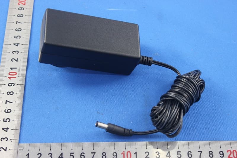
TZISDL9030DB
Nov 16, 2015PROFESSIONAL HD KARAOKE SYSTEM WITH BLUETOOTH
Equipment Class
DSS - Part 15 Spread Spectrum TransmitterTZISDL366
Sep 14, 2015HD KARAOKE SYSTEM WITH BLUETOOTH
Equipment Class
DSS - Part 15 Spread Spectrum Transmitter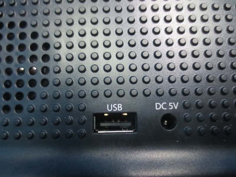
TZI-CN897153
Sep 08, 2015Bluetooth Alarm Clock
Equipment Class
DSS - Part 15 Spread Spectrum Transmitter
TZI-BT054
Sep 23, 2014Smart Bulb
Equipment Class
DTS - Digital Transmission System