TZQWQ110HUB4Wireless USB 4-Port Hub
WiQuest Communications Inc.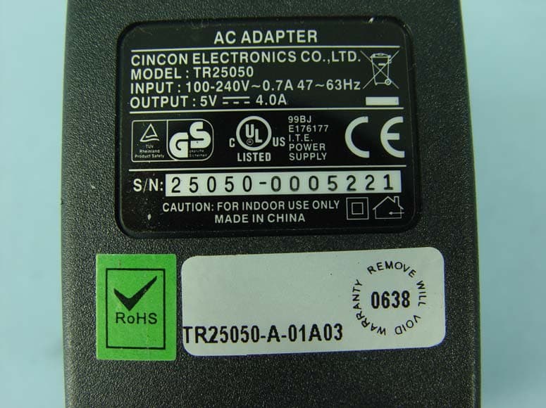
Click to zoom
Application Details
- Equipment Class
- UWB - Ultra Wideband Transmitter
- Date of Grant
- Jan 24, 2008
- Application Purpose
- Original Equipment
- Date of Application
- Sep 20, 2007
- Equipment Note
- Wireless USB 4-Port Hub
- Frequency Range
- 3100.00000000 - 4800.00000000
- Company
- WiQuest Communications Inc.
- Country
- United States
Documents & Files
Document Text
Text extracted from the exhibit documents filed with the FCC. Open a document above to read the original.
Users Manual
915 Enterprise Blvd, Suite 200 Allen, Texas 75013 www.WiQuest.com WiQuest Wireless USB 4-Port Hub OEM Evaluation Manual Version 0.1 WiQuest Communications, Inc. WQST110RDK-HUB-USB4 UG 915 Enterprise Blvd, Suite 200 Allen, Texas 75013 www.WiQuest.com 1 Wireless 4-Port USB Hub Users Guide WQST110RDK-HUB-USB4 UG Revision 0.1, September 21, 2007 CONTENTS : RIGHTS.......................................................................................................................................................................................... 2 REGULATORY NOTICES........................................................................................................................................................ 3 INTRODUCTION.......................................................................................................................................................................... 4 1 WQST110RDK-HUB-USB4 FEATURES........................................................................................................................ 4 1.1 HARDWARE FEATURES............................................................................................................................................... 4 1.2 SYSTEM REQUIREMENTS............................................................................................................................................ 4 2 INSTALLING THE WQST110RDK-HUB-USB4 WIRELESS USB HUB DRIVER AND SOFTWARE.................................. 4 2.1 INSTALLING THE WQST110RDK-HUB-USB4 WIRELESS USB DRIVER................................................................. 4 2.2 INSTALLING THE USB DRIVERS AND THE EVK CONTROL CENTER (ECC)............................................................... 5 2.3 CONNECT THE WQST110RDK-HUB-USB4 WIRELESS USB HUB HARDWARE..............................................10 3 EVK CONTROL CENTER (ECC)......................................................................................................................................13 3.1 RUNNING THE EVK CONTROL CENTER APPLICATION.............................................................................................14 3.2 SELECT THE HOST INTERFACE...................................................................................................................................14 3.2.1 SELECT THE DEVICE IDENTIFIER (ADDRESS) AND TIME FREQUENCY CODE # ........................................................14 3.2.2 TRANSMIT WINDOW...................................................................................................................................................15 3.2.3 RECEIVE WINDOW.....................................................................................................................................................17 4 APPENDIX A: TROUBLESHOOTING..................................................................................................................................19 4.1 THE WIRELESS USB HUB IS NOT FUNCTIONAL......................................................................................................19 4.2 I CAN’T CONNECT TO THE WIRELESS USB HUB.....................................................................................................19 www.WiQuest.com 2 Wireless 4-Port USB Hub Users Guide WQST110RDK-HUB-USB4 UG Revision 0.1, September 21, 2007 Rights Rights to use this documentation are set forth in the License Agreement included with the WQST110RDK-HUB-USB4 Wireless USB Hub module. © WiQuest Communications, Inc. 2006. All rights reserved. All right, title and interest, copyrights, patents, know-how, trade secrets, and other intellectual property relating to this publication and to the WQST110RDK-HUB-USB4 product are proprietary products of WiQuest Communications, Inc. (“WiQuest”). Any and all other trademarks, product names, and other intellectual property rights are the sole property of their respective owners. If this guide is distributed with software that includes an end user agreement, this guide, as well as the software describe in it, is furnished under license and may be used in accordance with the terms of such license. Except as permitted by such license, no part of this guide may be reproduced, stored in a retrieval system, or transmitted, in any form, or by any means, electronic, mechanical, recording, or otherwise, without the prior written permission of WiQuest Communications, Inc. Please note that the content in this guide is protected under copyright law even if it is not distributed with software that includes an end user license agreement. The content of this guide is furnished for information al use only and does not form part of any quotation or contract. It is subject to change without notice, and should not be construed as a commitment by WiQuest Communications, Inc. WiQuest Communications, Inc. assumes no responsibility or liability for any errors or inaccuracies that may appear in the information content contained in this guide. Microsoft and Windows are either registered trademarks or trademarks of Microsoft Corporation in the United States and/or other countries. WiQuest™ and WiDV™ are registered trademarks of WiQuest Communications, Inc.. No right, license, or interest to such trademark is granted hereunder. www.WiQuest.com 3 Wireless 4-Port USB Hub Users Guide WQST110RDK-HUB-USB4 UG Revision 0.1, September 21, 2007 Regulatory Notices Federal Communication Commission Interference Statement This equipment has been tested and found to comply with the limits for a Class B digital device, pursuant to Part 15 of the FCC Rules. These limits are designed to provide reasonable protection against harmful interference in a residential installation. This equipment generates, uses and can radiate radio frequency energy and, if not installed and used in accordance with the instructions, may cause harmful interference to radio communications. However, there is no guarantee that interference will not occ…
Text truncated - open the document above for the full version.
Cover Letter(s)
2428x3490x16M jpeg
Cover Letter(s)
2552x3508x16M jpeg
External Photos
Page 1 CONSTRUCTION PHOTOS OF EUT Page 2
ID Label/Location Info
LABEL LOCATION FCC ID: TZQWQ110HUB4
ID Label/Location Info
900x300x16M bmp
Internal Photos
Page 3 Page 4 Page 5
Operational Description
WiQuest Communications, Inc. 915 Enterprise Blvd, Suite 200 Allen, Texas 75013 The New Frontier of Wireless Main: +1 214-547-1600 www.wiquest.com Fax: +1 214-547-1606 Theory of Operation WiQuest’s Wireless USB 4-Port Hub is a cost-effective, highly-integrated design that provides wireless UWB high- speed services for wired USB devices. With this reference design, WiQuest enables equipment manufacturers to build a complete Device Wired Adapter (DWA). The Wireless USB Hub design provides a complete end-to-end solution based on the Certified Wireless USB specification from the USB-IF while leveraging WiQuest breakthrough wireless performance. The WiQuest Wireless USB 4-Port Hub Reference Design Kit is shipped as a complete package including both hardware and software support. The hardware information includes a working Hub sample along with schematics, layout source files, a detailed bill-of-material, design manual, user’s guide, and a quick-start guide. The software package includes DWA firmware along with the WiQuest Microsoft Windows-based utility which supports device discovery, multiple association options, field upgrade functionality, and comprehensive diagnostics. The WiQuest Wireless USB 4-Port Hub is designed around WiQuest’s WQST110 and WQST101, the industry’s leading high-performance ultrawideband (UWB) chipset. The WQST110 includes a WiMedia-based ultrawideband media access controller (MAC) and physical layer (PHY) baseband processor. The WQST101 is a direct conversion UWB RF transceiver. WiQuest Communications Wireless USB Hub (WQST110RDK-HUB-USB4) Reference Design is an Ultrawideband (UWB) WiMedia Mode 1-compliant device that operates in the 3168-4752MHz Band group. The WiQuest Wireless USB Hub transmits a WiMedia UWB signal that has instantaneous bandwidth (BW) greater than 500MHz, or fractional occupied BW greater than 20 percent. The 1584MHz wide band represents 40 percent bandwidth (fractional bandwidth equals 2*(Fh-Fl)/(Fh+Fl), where Fh is upper boundary and Fl is lower boundary). Band Group 1 is divided into 3 individual bands, each 528MHz wide, with center frequencies of 3432MHz, 3960MHz and 4488MHz, respectively. The WiQuest Wireless USB transmits either by hopping between the 3 bands or stationary on each band. FCC Part 15 regulation in Subpart F, Section 15.517 and 15.519 specifies maximum average Equivalent Iso-tropically Radiated Power (EIRP) of –41.3dBm (53.9dBuV/m) measured using a resolution bandwidth of 1MHz. EIRP in dBm could be converted to a field strength, in dBuV/m at 3 meters, by adding 95.2dB. Since the WiQuest Wireless USB Hub occupies approximately 1584MHz while hopping (528MHz instantaneously) the average transmitted power is on the order of -9.3dBm (or -14dBm when not hopping). The 528MHz wide signal is composed of 122 modulated Orthogonal Frequency Division Multiplexed (OFDM) sub-carriers.
Test Report
Report No.:RF960308L02 1 Report Format Version 2.0.6 FCC TEST REPORT REPORT NO.: RF960308L02 MODEL NO.: WQ110-HUB4 RECEIVED: Mar. 08, 2007 TESTED: Mar. 16 ~ Jul. 24, 2007 ISSUED: Jul. 25, 2007 APPLICANT: WiQuest Communications, Inc. ADDRESS: 915 Enterprise, Allen, Texas, United States, 75013 ISSUED BY: Advance Data Technology Corporation LAB ADDRESS: 47 14 th Lin, Chiapau Tsun, Linko, Taipei, Taiwan, R.O.C. TEST LOCATION: No. 19, Hwa Ya 2 nd Rd., Kueishan, Taoyuan, Taiwan, R.O.C. This test report consists of 44 pages in total. It may be duplicated completely for legal use with the approval of the applicant. It should not be reproduced except in full, without the written approval of our laboratory. The client should not use it to claim product endorsement by TAF or any government agencies. The test results in the report only apply to the tested sample. Report No.:RF960308L02 2 Report Format Version 2.0.6 Table of Contents 1 CERTIFICATION ........................................................................................................4 2 SUMMARY OF TEST RESULTS ................................................................................5 2.1 MEASUREMENT UNCERTAINTY .............................................................................5 3 GENERAL INFORMATION.........................................................................................6 3.1 GENERAL DESCRIPTION OF EUT...........................................................................6 3.2 DESCRIPTION OF TEST MODES.............................................................................7 3.2.1 CONFIGURATION OF SYSTEM UNDER TEST ........................................................7 3.2.2 TEST MODE APPLICABILITY AND TESTED CHANNEL DETAIL.............................8 3.3 GENERAL DESCRIPTION OF APPLIED STANDARDS ..........................................10 3.4 DESCRIPTION OF SUPPORT UNITS ..................................................................... 11 3.5 OPEARTIONAL LIMIATIONS ...................................................................................12 4 TEST TYPES AND RESULTS ..................................................................................14 4.1 CONDUCTED EMISSION MEASUREMENT ...........................................................14 4.1.1 LIMITS OF CONDUCTED EMISSION MEASUREMENT ........................................14 4.1.2 TEST INSTRUMENTS .............................................................................................14 4.1.3 TEST PROCEDURES ..............................................................................................15 4.1.4 DEVIATION FROM TEST STANDARD ....................................................................15 4.1.5 TEST SETUP ...........................................................................................................16 4.1.6 EUT OPERATING CONDITIONS .............................................................................16 4.1.7 TEST RESULTS .......................................................................................................17 4.2 RADIATED EMISSION MEASUREMENT (FOR 15.517 (c)) ....................................19 4.2.1 LIMITS OF RADIATED EMISSION MEASUREMENT .............................................19 4.2.2 INSTRUMENT SETUP VALUE AND MEASUREMENT DISTANCE ........................20 4.2.3 TEST INSTRUMENTS .............................................................................................21 4.2.4 TEST PROCEDURES ..............................................................................................22 4.2.5 DEVIATION FROM TEST STANDARD ....................................................................22 4.2.6 TEST SETUP ...........................................................................................................23 4.2.7 EUT OPERATING CONDITIONS .............................................................................23 4.2.8 TEST RESULTS .......................................................................................................24 4.3 RADIATED EMISSION MEASUREMENT (FOR 15.517 (d))....................................27 4.3.1 LIMITS OF RADIATED EMISSION MEASUREMENT .............................................27 4.3.2 INSTRUMENT SETUP VALUE AND MEASUREMENT DISTANCE ........................28 4.3.3 TEST INSTRUMENTS .............................................................................................29 4.3.4 TEST PROCEDURES ..............................................................................................30 4.3.5 DEVIATION FROM TEST STANDARD ....................................................................30 4.3.6 TEST SETUP ...........................................................................................................31 4.3.7 EUT OPERATING CONDITIONS .............................................................................31 4.3.8 TEST RESULTS .......................................................................................................32 4.4 UWB BANDWIDTH MEASUREMENT .....................................................................33 4.4.1 LIMITS OF UWB BANDWIDTH MEASUREMENT...................................................33 4.4.2 INSTRUMENT SETUP VALUE AND MEASUREMENT DISTANCE ........................33 4.4.3 TEST INSTRUMENT................................................................................................33 Report No.:RF960308L02 3 Report Format Version 2.0.6 4.4.4 TEST PROCEDURE ................................................................................................33 4.4.5 DEVIATION FROM TEST STANDARD ....................................................................33 4.4.6 TEST SETUP ...........................................................................................................34 4.4.7 EUT OPERATING CONDITIONS .............................................................................34 4.4.8 TEST RESULTS ..........................…
Text truncated - open the document above for the full version.
Test Setup Photos
1 PHOTOGRAPHS OF THE TEST CONFIGURATION CONDUCTED EMISSION TEST 2 RADIATED EMISSION TEST
Contact Information
Applicant
Jovica Jovanovski(Hardware Core Engineering Manager)
Technical Contact
Advance Data Technology Corporation (Hwa Ya)Gary Chang
[email protected]886-3-3183232
No. 19, Hwa Ya 2nd Rd., Kwei Shan Hsiang · Taoyuan Hsien · Taiwan
Non-Technical Contact
Advance Data Technology CorporationEllis Wu
[email protected]886-3-3183232
Test Firm
Bureau Veritas CPS (H.K.) Ltd. Taoyuan BranchRichard Chen
Technical Specifications
| # | Rule Parts | Frequency Range | Power Output |
|---|---|---|---|
| 1 | 15F | 3.10 GHz - 4.80 GHz | - |
Other Applications from WiQuest Communications Inc.
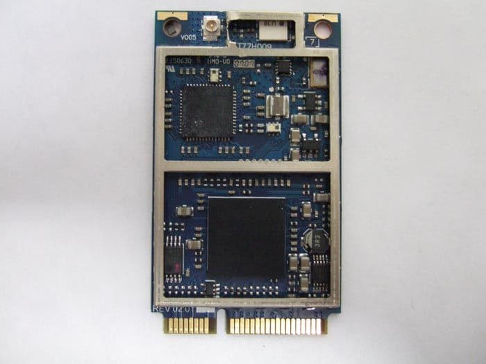
TZQWQ110MC
Aug 08, 2007Wireless USB Mini Card Module
Equipment Class
UWB - Ultra Wideband Transmitter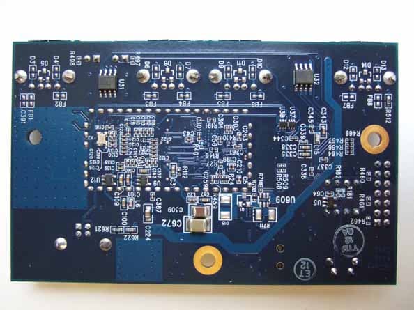
TZQ110USB4HUB
Oct 29, 2006Wireless USB HUB
Equipment Class
UWB - Ultra Wideband Transmitter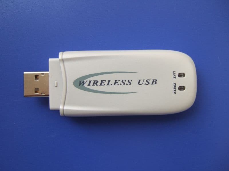
TZQ100ADA
Oct 22, 2006Wireless USB Dongle
Equipment Class
UWB - Ultra Wideband Transmitter