U28FU2BTEPPhearing instrument with short range low power wireless radio
Oticon A/S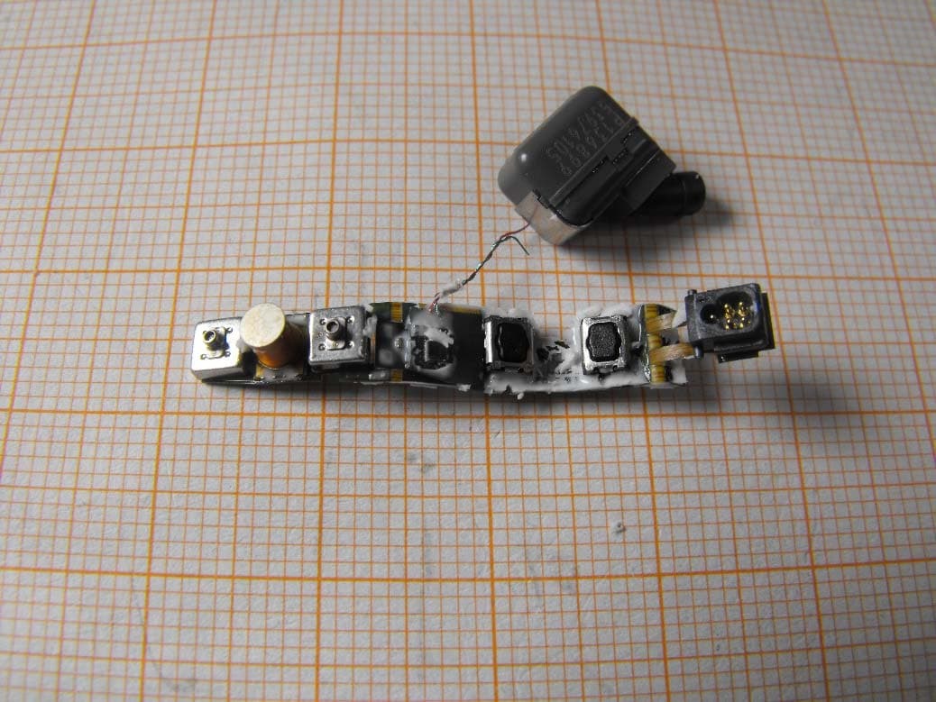
Click to zoom
Application Details
- Equipment Class
- DXX - Part 15 Low Power Communication Device Transmitter
- Date of Grant
- Jun 29, 2015
- Application Purpose
- Original Equipment
- Date of Application
- Jun 29, 2015
- Equipment Note
- hearing instrument with short range low power wireless radio
- Frequency Range
- 3.84000000 - 3.84000000
- Company
- Oticon A/S
- Country
- Denmark
Documents & Files
Document Text
Text extracted from the exhibit documents filed with the FCC. Open a document above to read the original.
Users Manual
PEOPLE FIRST Oticon Radio Model - Quick Installation Guide Radio Model Name: Fusion 2 BTE13PP The Fusion 2 BTE13PP radio model is a low power, short range, inductive radio transceiver working at 3.84 MHz. It can be seen below: Fusion 2 BTE13PP Radio Model – Top Side The most important parts of the radio module are a Digital-Signal-Processor (DSP), a radio Front-End (FE), an EEPROM memory, a telecoil and an antenna coil – all mounted on the same main flex PCB. On the top side besides the radio Front-End, EEPROM and telecoil, also switches for user inter action (e.g. volume control), two microphones, a programming plug and pads for connecting the battery can be seen. The radio model is intended to be installed in Oticon, Bernafon, Sonic and affiliated wireless hearing aid devices of the BTE (Behind-The-Ear) PP (Power Plus) wearing styles. Oticon A/S Kongebakken 9 DK-2765 Smørum www.oticon.com Main +45 39 17 71 00 Fax +45 39 27 79 00 Denmark CVR-no. 42334219 1 PEOPLE FIRST Oticon Radio Model - Quick Installation Guide Radio Model Name: Fusion 2 BTE13PP The DSP is the main processor controlling the functionality of the amplifier and the FE is a complete radio transceiver, including both transmitter, receiver and local oscillators. The Fusion 2 BTE13PP radio module also includes all voltage regulators inside the DSP and FE and buffered data programming inputs (PC_DATA and PC_CLOCK) on board . Fusion 2 BTE13PP Radio Model – Bottom Side On the bottom side of the radio model the DSP, the antenna coil and pads for connecting the audio receiver can be seen. The module only requires a single cell battery and an external audio receiver (speaker) to be attached and plastic shells holding everything together in order to be operational. Oticon A/S Kongebakken 9 DK-2765 Smørum www.oticon.com Main +45 39 17 71 00 Fax +45 39 27 79 00 Denmark CVR-no. 42334219 2 PEOPLE FIRST Oticon Radio Model - Regulatory Label Information Radio Model Name: Fusion 2 BTE13PP Contains: FCC ID: U28FU2BTEPP IC: 1350B-FU2BTEPP NOTICE: This device complies with Part 15 of the FCC Rules and with RSS-210 of Industry Canada. Operation is subject to the following two conditions: (1) This device may not cause harmful interference, and (2) This device must accept any interference received, including interference that may cause undesired operation. Changes or modifications made to this equipment not expressly approved by Oticon A/S may void the FCC authorization to operate this equipment. Le présent appareil est conforme aux CNR d'Industrie Canada applicables aux appareils radio exempts de licence. L'exploitation est autorisée aux deux conditions suivantes: (1) l'appareil ne doit pas produire de brouillage, et (2) l'utilisateur de l'appareil doit accepter tout brouillage radioélectrique subi, même si le brouillage est susceptible d'en compromettre le fonctionnement. Oticon A/S Kongebakken 9 DK-2765 Smørum www.oticon.com Main +45 39 17 71 00 Fax +45 39 27 79 00 Denmark CVR-no. 42334219 3
Cover Letter(s)
PEOPLE FIRST CONFIDENTIALITY REQUEST for Certification Service in USA Federal Communication Commission Equipment Authorization Division, Application Processing Branch 7435 Oakland Mills Road Columbia, MD 21048 June 19, 2015. TO WHOM IT MAY CONCERN Pursuant to Paragraphs §0.457 and 0.459 of the Commission’s Rules (47 C.F.R.) and Section §552(b)(4) of the Freedom of Information Act, we request confidentiality for the following product(s) : FCC ID Model name U28FU2BTEPP Fusion 2 BTE13PP For the product(s) stated above, we request that the following information be held confidential: 1. Circuit diagrams, BOM, and PCBs submitted as Equipment Authorization Electronic Filing attachment: “Bill of Material”, “Circuit Diagram” and “PCB Layout”. 2. Block diagram submitted as Equipment Authorization Electronic Filing attachment: “Block diagram”. 3. Operational description submitted as Equipment Authorization Electronic Filing attachment: “Operational Description” or “Product Description”. The above exhibits contain our trade secrets and proprietary information that could be of benefit to our competitors. If you have any questions, please feel free to contact me at the address shown below. Sincerely, Lars Bresler, QM-manager Oticon A/S Kongebakken 9 2765 Smorum DK-Denmark Phone: +45 3913 7100
Cover Letter(s)
PEOPLE FIRST FCC/IC Modular Approval Statement Receiver Federal Communication Commission Equipment Authorization Devision, Application Processing Branch 7435 Oakland Mills Road Columbia, MD 21048 Certification and Engineering Bureau Industry Canada Spectrum Engineering Branch 3701 Carling Avenue, Building 94 Ottawa, Ontario K2H 8S2 Subject: Limited Modular Approval Statement Date: 23 rd of June, 2015. FCC Certification Number: U28FU2BTEPP Only applicable for IC certification: IC Company Number: 1350B UPN: (Unique Product No) FU2BTEPP HVIN (Hardware Ver. ID): Fusion 2 BTE13PP PMN: (Product Marketing Name) Fusion 2 BTE13PP HMN: (Host Marketing Name) N/A FVIN: (Firmware Version Identification Number) Fusion 2 esw - ver. 5.5.0.b TO WHOM IT MAY CONCERN Pursuant to Paragraphs RSP-100 Issue 10 November 2014 Item 7.3 and CFR § 15.212, we herewith declare for our module. Modular approval requirement Yes No * (a) The radio elements must have the radio frequency circuitry be shielded. Physical/discrete and tuning capacitors may be located external to the shield, but must be on the module assembly. X *Please provide a detailed explanation if the answer is “No.”: There is no complete RF shield attached to the radio module, only the ground layer in its PCB. Therefore Oticon is only requesting a limited modular approval for the module. (b) The module shall have buffered modulation/data input(s) (if such inputs are provided) to ensure that the module will comply with the requirements set out in the applicable RSS standard under conditions of excessive data rates or over-modulation. X *Please provide a detailed explanation if the answer is “No.”: (c) The module shall have its own power supply regulation on the module. This is to ensure that the module will comply with the requirements set out in the applicable standard regardless of the design of the power supplying circuitry in the host device which houses the module. X *Please provide a detailed explanation if the answer is “No.”: 1 PEOPLE FIRST FCC/IC Modular Approval Statement (d) The module shall comply with the provisions for external power amplifiers and antennas detailed in this standard. The equipment certification submission shall contain a detailed description of the configuration of all antennas that will be used with the module. X *Please provide a detailed explanation if the answer is “No.”: (e) The module shall be tested for compliance with the applicable standard in a stand-alone configuration, i.e. the module must not be inside another device during testing. X *Please provide a detailed explanation if the answer is “No.”: (f) The module shall comply with the Category I equipment labeling requirements and CFR § 15.212(a)(1)(vi). (X) *Please provide a detailed explanation if the answer is “No.”: The module is intended to be used inside Oticon affiliated hearing instruments only, which are too small to carry the IC label legible without magnification. Therefore the label is put in the installation guide and/or user manual, but not on the products carrying the module inside. This is possible due to a label exemption granted by Industry Canada. (g) The module shall comply with applicable RSS-102 exposure requirements and any applicable FCC RF exposure requirement which are based on the intended use/configurations. X *Please provide a detailed explanation if the answer is “No.”: Only applicable for IC certification: (h) Is the modular device for an Industry Canada licensed exempt service? X Only applicable for FCC certification: (i) The modular transmitter complies with all applicable FCC rules. Instructions for maintaining compliance are given in the user instructions. X If you have any questions, please feel free to contact us at the address shown below Best Regards, Lars Bresler, QM-manager Oticon A/S Kongebakken 9 2765 Smorum - DK-Denmark Phone: +45 3913 7100 INFO for applicant: LMA may be granted when one or more of the requirements in the table above cannot be demonstrated. LMA will also be issued in those instances where applicants can demonstrate that they will retain control over the final installation of the device, such that compliance of the end product is assured. In such cases, an operating condition on the LMA for the module must state that the module is only approved for use when installed in devices produced by a specific manufacturer. When LMA is sought, the application for equipment certification must specifically state how control of the end product, into which the module will be installed, will be maintained, such that full compliance of the end product is always ensured. 2
Cover Letter(s)
PEOPLE FIRST SHORT-TERM CONFIDENTIALITY REQUEST Federal Communication Commission Equipment Authorization Division, Application Processing Branch 7435 Oakland Mills Road Columbia, MD 21048 June 19, 2015. TO WHOM IT MAY CONCERN Pursuant to the recent upgrade to the Office of Engineering and Technology’s (OET) Equipment Authorization System on 6/15/04 (ref. DA 04 –1705), Oticon A/S requests temporarily confidentiality for the following product: FCC ID Number Product Title/Model U28FU2BTEPP Fusion 2 BTE13PP For the product stated above, we request that the following information be held confidential: 1. External and Internal Photographs 2. Test Setup Photos 3. User Manual We request this confidentiality on the basis of ensuring that business sensitive information remains confidential for 97 days. If you have any questions, please feel free to contact me at the address shown below. Sincerely, Lars Bresler, QM-manager Oticon A/S Kongebakken 9 2765 Smorum DK-Denmark Phone: +45 3913 7100
External Photos
Test report no.: 1-9507_15-01-01_AnnexB Page 1 of 6 Annex B This test report annex is electronically signed and valid without handwriting signature. For verification of the electronic signatures, the public keys can be requested at the testing laboratory. Test report annex authorised: Tobias Wittenmeier Testing Manager Radio Communications & EMC Test report no.: 1-9507_15-01-01_AnnexB Page 2 of 6 Internal photos of the EUT Photo 1: Photo 2: Test report no.: 1-9507_15-01-01_AnnexB Page 3 of 6 Photo 3: Photo 4: Test report no.: 1-9507_15-01-01_AnnexB Page 4 of 6 Photo 5: Photo 6: Test report no.: 1-9507_15-01-01_AnnexB Page 5 of 6 Photo 7: Test report no.: 1-9507_15-01-01_AnnexB Page 6 of 6 Document history Version Applied changes Date of release Initial release 2015-05-19
ID Label/Location Info
PEOPLE FIRST Oticon Radio Model - Regulatory Label Information Radio Model Name: Fusion 2 BTE13PP Contains: FCC ID: U28FU2BTEPP IC: 1350B-FU2BTEPP NOTICE: This device complies with Part 15 of the FCC Rules and with RSS-210 of Industry Canada. Operation is subject to the following two conditions: (1) This device may not cause harmful interference, and (2) This device must accept any interference received, including interference that may cause undesired operation. Changes or modifications made to this equipment not expressly approved by Oticon A/S may void the FCC authorization to operate this equipment. Le présent appareil est conforme aux CNR d'Industrie Canada applicables aux appareils radio exempts de licence. L'exploitation est autorisée aux deux conditions suivantes: (1) l'appareil ne doit pas produire de brouillage, et (2) l'utilisateur de l'appareil doit accepter tout brouillage radioélectrique subi, même si le brouillage est susceptible d'en compromettre le fonctionnement. Oticon A/S Kongebakken 9 DK-2765 Smørum www.oticon.com Main +45 39 17 71 00 Fax +45 39 27 79 00 Denmark CVR-no. 42334219 1
Internal Photos
Test report no.: 1-9507_15-01-01_AnnexB Page 1 of 6 Annex B This test report annex is electronically signed and valid without handwriting signature. For verification of the electronic signatures, the public keys can be requested at the testing laboratory. Test report annex authorised: Tobias Wittenmeier Testing Manager Radio Communications & EMC Test report no.: 1-9507_15-01-01_AnnexB Page 2 of 6 Internal photos of the EUT Photo 1: Photo 2: Test report no.: 1-9507_15-01-01_AnnexB Page 3 of 6 Photo 3: Photo 4: Test report no.: 1-9507_15-01-01_AnnexB Page 4 of 6 Photo 5: Photo 6: Test report no.: 1-9507_15-01-01_AnnexB Page 5 of 6 Photo 7: Test report no.: 1-9507_15-01-01_AnnexB Page 6 of 6 Document history Version Applied changes Date of release Initial release 2015-05-19
Test Report
TEST REPORT Test report no.: 1-9507/15-01-03-A Testing laboratory Applicant CETECOM ICT Services GmbH Untertuerkheimer Strasse 6 – 10 66117 Saarbruecken / Germany Phone: + 49 681 5 98 - 0 Fax: + 49 681 5 98 - 9075 Internet: http://www.cetecom.com e-mail: [email protected] Accredited Testing Laboratory: The testing laboratory (area of testing) is accredited according to DIN EN ISO/IEC 17025 (2005) by the Deutsche Akkreditierungsstelle GmbH (DAkkS) The accreditation is valid for the scope of testing procedures as stated in the accreditation certificate with the registration number: D-PL-12076-01-00 Oticon A/S Kongebakken 9 2765 Smørum / DENMARK Phone: +45 39 17 71 00 Fax: -/- Contact: Jørgen Peter Hanuscheck e-mail: [email protected] Phone: +45 39 13 85 38 Manufacturer Oticon A/S Kongebakken 9 2765 Smørum / DENMARK Test standard/s 47 CFR Part 15 Code of Federal Regulations; Title 47: Telecommunication; Vol. 1: Part 15 – Radio Frequency Devices. RSS - 210 Issue 8 Spectrum Management and Telecommunications Radio Standards Specification - Licence-exempt Radio Apparatus (All Frequency Bands): Category I Equipment RSS - 210 Issue 8 Amendment 1 RSS-210, Amendment 1 — Licence-Exempt, Low-Power Radio Apparatus Operating in the Television Bands (February 2015) For further applied test standards please refer to section 3 of this test report. Test Item Kind of test item: Hearing Aid Model name: Fusion 2 BTE13PP FCC ID: U28FU2BTEPP IC: 1350B-FU2BTEPP Frequency: 3.84 MHz Technology tested: Magnetic coupling Antenna: Integrated ferrite coil antenna Power supply: 1.40 V DC by zinc – air battery Temperature range: 0°C to +35°C This test report is electronically signed and valid without handwriting signature. For verification of the electronic signatures, the public keys can be requested at the testing laboratory. Test report authorised: Test performed: Stefan Bös Tobias Wittenmeier Lab Manager Testing Manager Radio Communications & EMC Radio Communications & EMC Test report no.: 1-9507/15-01-03-A Page 2 of 24 1 Table of contents 1 Table of contents ............................................................................................................................................ 2 2 General information ....................................................................................................................................... 3 2.1 Notes and disclaimer .......................................................................................................................... 3 2.2 Application details ............................................................................................................................... 3 3 Test standard/s ............................................................................................................................................... 3 4 Test environment ............................................................................................................................................ 4 5 Test item .......................................................................................................................................................... 4 Additional information ................................................................................................................................... 4 6 Test laboratories sub-contracted ................................................................................................................. 4 7 Description of the test setup ......................................................................................................................... 5 7.1 Shielded semi anechoic chamber ...................................................................................................... 6 7.2 Shielded fully anechoic chamber ...................................................................................................... 7 7.3 Conducted measurements ................................................................................................................. 8 8 Summary of measurement results ............................................................................................................... 9 9 Additional comments ................................................................................................................................... 10 10 Measurement results ................................................................................................................................ 11 10.1 Timing of the transmitter ............................................................................................................... 11 10.2 Bandwidth of the modulated carrier ............................................................................................ 12 10.3 Field strength of the fundamental ................................................................................................ 15 10.4 Fieldstrength of the harmonics and spurious ............................................................................ 16 10.5 Receiver spurious emissions ....................................................................................................... 19 10.6 Conducted limits ............................................................................................................................ 21 11 Observations ............................................................................................................................................. 22 Annex A Document history .......................................................................................................................... 23 Annex B Further information ........................................................................................................................ 23 Annex C Accreditation Certificate ............................................................................................................... 24 Test report no.: 1-9507/15-01-03-A Pa…
Text truncated - open the document above for the full version.
Test Setup Photos
Test report no.: 1-9507_15-01-01_AnnexD Page 1 of 7 Annex D This test report annex is electronically signed and valid without handwriting signature. For verification of the electronic signatures, the public keys can be requested at the testing laboratory. Test report annex authorised: Tobias Wittenmeier Testing Manager Radio Communications & EMC Test report no.: 1-9507_15-01-01_AnnexD Page 2 of 7 EUT Test setup photos Photo 1: Photo 2: Test report no.: 1-9507_15-01-01_AnnexD Page 3 of 7 Photo 3: Photo 4: Test report no.: 1-9507_15-01-01_AnnexD Page 4 of 7 Photo 5: Photo 6: Test report no.: 1-9507_15-01-01_AnnexD Page 5 of 7 Photo 7: Photo 8: Test report no.: 1-9507_15-01-01_AnnexD Page 6 of 7 Photo 9: Test report no.: 1-9507_15-01-01_AnnexD Page 7 of 7 Document history Version Applied changes Date of release Initial release 2015-05-19
Contact Information
Applicant
Per Klaus Nielsen(Certification Manager)
Test Firm
cetecom advanced GmbHGerald Schmidt
Technical Specifications
| # | Rule Parts | Frequency Range | Power Output |
|---|---|---|---|
| 1 | 15C | 3.84 MHz - 3.84 MHz | - |
Other Applications from Oticon A/S
U28FU2DRIT
Aug 10, 2014Hearing Aid Module
Equipment Class
DXX - Part 15 Low Power Communication Device Transmitter
U28FU2CICWL
Jun 22, 2014Hearing Aid
Equipment Class
DXX - Part 15 Low Power Communication Device Transmitter
U28WLPS10
Apr 09, 2014WLP Special
Equipment Class
DXX - Part 15 Low Power Communication Device Transmitter
U28TVBOX03
Aug 19, 2013TV Adapter 2.0
Equipment Class
DSS - Part 15 Spread Spectrum Transmitter
U28CL2STRM
Dec 19, 2012Audio Streaming Module
Equipment Class
DSS - Part 15 Spread Spectrum Transmitter