U2BRL039AT92.4G Digital Proportional R/C system
Radiolink Electronic Limited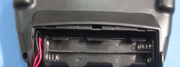
Click to zoom
Application Details
- Equipment Class
- DSS - Part 15 Spread Spectrum Transmitter
- Date of Grant
- Dec 21, 2014
- Application Purpose
- Original Equipment
- Date of Application
- Dec 20, 2014
- Equipment Note
- 2.4G Digital Proportional R/C system
- Frequency Range
- 2409.00000000 - 2474.00000000
- Company
- Radiolink Electronic Limited
- Country
- China
Documents & Files
Document Text
Text extracted from the exhibit documents filed with the FCC. Open a document above to read the original.
Users Manual
RADIOLINK AT9 (FHSS) INSTRUCTION MANUAL RADIOLINK ELETRONIC LIMITED Technical updates and additional programming examples available at: http://www. radiolink.com.cn 1 INTRODUCTION Thank you for purchasing Radiolink 2.4 GHz 9 shift remote control system -- AT9 . This system is extremely versatile, it is the most complete remote control device as so far in our product series, it can operate helicopter, fixed-wing glider, aircraft all four models . Communication system adopts anti-interference strongest FHSS. Despite the powerful function, humanized menu design applicable to both beginners and skilled person. In order to better use remote control equipment and ensure flight safety, please read the instructions carefully, when we write the instruction to u se the familiar and simple words to make it easy for beginners to understand the name and formulation. Suggestion: when you read this manual, please open the remote control and receiver and connect the receiver steering gear and other related equipment, operating while reading. When you read get some difficulties, please refer to the manual or call our after-sales (+86-0755-88361717) and login BBS (such as www.5imx.com, www.5imx.com, www.5imx.com, www.rcfans.com) to check the issues related answer to questions. Due to unforeseen changes in production procedures, the information contained in this manual is subject to change without notice. More information please check our website as below: http://www.radiolink.com.cn Support and Service: It is recommended to have your Radiolink equipment serviced annually during your hobby’s “off season” to ensure safe operation. Please feel free to browse our GUEST BOOK for assistance in operation, use and programming. Please be sure to regularly visit the Service and Support web site at www.radiolink.com.cn. This page includes extensive programming, use, set up and safety information on the AT9 radio system and is updated regularly. Any technical updates and manual corrections will be available on this web pages.If you do not find the answers to your questions there, please see the end of our contact area for information on contacting us via email for the most rapid and convenient response. FOR SERVICE ONLY: Please start here for getting more service. www.radiolink.com.cn Phone:+86-755-88361717 Email:[email protected] FOR SUPPORT : (PROGRAMMING AND USER QUESTIONS) Please start here for answers to most questions: www.radiolink.com.cn Phone:86-755-88361717 Email:[email protected] 2 Note:About flying While you are getting ready to fly,if you place your transmitter on the ground ,be sure that the wind won’t tip it over. If it is knocked over,the throttle stick may be accidentally moved, causing the engine to speed up. Also, damage to your transmitter may occur. Other than 2.4GHz system: Before taxiing, be sure to extend the transmitter antenna to its full length.collapsed antenna will reduce your flying range and cause a loss of control.It is a good idea to avoid pointing the transmitter antenna directly at the model, since the signal is weakest in that direction. In order to maintain complete control of your aircraft it is important that it remains visible at all times . Flying behind large objects such as buildings, grain bins, etc. is not suggested. Doing so may result in the reduction of the quality of the radio frequency link to the model. 2.4GHz system: DO not grasp the transmitter module’s antenna during flight.Doing so may degrade the quality of the radio frequency transmission. 2.4GHz system: As with all radio frequency transmissions, the strongest area of signal transmission is from the sides of the 9 shift transmitter module's antenna. As such, the antenna should not be pointed directly at the model.If yo ur flying style creates this situation,easily move the antenna to correct this situation. Warning!!! please don't fly in the rain! Rain or moisture may enter the transmitter internal through gaps in the antenna or joystick flight and cause your flight to instability even out of control. If inevitable will fly in the wet weather (such as game), please be sure to use plastic bags or waterproof cloth to cover your transmitter, please don't flight if there is lightning. This device complies with part 15 of the FCC Rules. Operation is subject to the following two conditions: (1) This device may not cause harmful interference, and (2) This device must accept any interference received, including interference that may cause undesired operation. This equipment has been tested and found to comply with the limits for a Class B digital device, pursuant to Part 15 of the FCC Rules. These limits are designed to provide reasonable protection against harmful interference in a residential installation. This equipment generates, uses and can radiate radio frequency energy and, if not installed and used in accordance with the instructions, may cause harmful interference to radio communications. However, there is no guarantee that interference will not occur in a particular installation. If this equipment does cause harmful interference to radio or television reception, which can be determined by turning the equipment off and on, the user is encouraged to try to correct the interference by one or more of the following measures: -- Reorient or relocate the receiving antenna. -- Increase the separation between the equipment and receiver. -- Connect the equipment into an outlet on a circuit different from that to which the receiver is connected. -- Consult the dealer or an experienced radio/TV technician for help. Changes or modifications not expressly approved by the party responsible for compliance could void your authority to operate the equipment. 3 TABLE OF CONTENTS 1 Part 1. INTRODUCTION OF AT9 SYSTEM...............................................................................5 1.1.1 Function of transmitter................................................................................................…
Text truncated - open the document above for the full version.
ID Label/Location Info
This device complies with part 15 of the FCC Rules. Operation is subject to the following two conditions: (1) this device may not cause harmful interference, and (2) this device must accept any interference received, including interference that maycause undesired operation.
ID Label/Location Info
Label location
RF Exposure Info
FCC ID: U2BRL039AT9 This device has a standalone transmission, and support handheld operations (extremity SAR exposure conditions). According to 447498 D01 General RF Exposure Guidance v05r02, section 4.3.1, the 1-g and 10-g SAR test exclusion thresholds for 100 MHz to 6 GHz at test separation distances ≤ 50 mm are determined by: [(max. power of channel, including tune-up tolerance, mW)/(min. test separation distance, mm)]·[√f(GHz)] ≤ 3.0 for 1-g SAR and ≤ 7.5 for 10-g extremity SAR. Worst Case Antenna Position Refer to above photos of the worst case antenna position, and minimum separation (10 mm) between antenna structure and the switch of the device may be touched during the transmissions. The maximum peak power is 14.97dBm (31.405mW) @ 2.409GHz, minimum test separation distance is 10 mm. [(max. power of channel, including tune-up tolerance, mW)/(min. test separation distance, mm)]·[√f(GHz)] =(31.405x1.55)/10=4.868 ≤ 7.5 SAR test for 10-g extremity exposure conditions is exempted.
Test Report
Global United Technology Services Co., Ltd. Report No.: GTSE14100174901 FCC REPORT Applicant: Radiolink Electronic Limited Address of Applicant: 3/F, BLD2, FuGuo industrial park, KaiFeng North Road, MeiLin Shenzhen China Equipment Under Test (EUT) Product Name: 2.4G Digital Proportional R/C system Model No.: AT9 FCC ID: U2BRL039AT9 Applicable standards: FCC CFR Title 47 Part 15 Subpart C Section 15.247:2013 Date of sample receipt: October 23, 2014 Date of Test: November 24-26, 2014 Date of report issued: November 26, 2014 Test Result : PASS * * In the configuration tested, the EUT complied with the standards specified above. Authorized Signature: Robinson Lo Laboratory Manager This report details the results of the testing carried out on one sample. The results contained in this test report do not relate to other samples of the same product and does not permit the use of the GTS product certification mark. The manufacturer should ensure that all products in series production are in conformity with the product sample detailed in this report. This report may only be reproduced and distributed in full. If the product in this report is used in any configuration other than that detailed in the report, the manufacturer must ensure the new system complies with all relevant standards. Any mention of GTS or testing done by GTS in connection with, distribution or use of the product described in this report must be approved by GTS in writing. This document cannot be reproduced except in full, without prior written approval of the Company. Any unauthorized alteration, forgery or falsification of the content or appearance of this document is unlawful and offenders may be prosecuted to the fullest extent of the law. Unless otherwise stated the results shown in this test report refer only to the sample(s) tested and such sample(s) are retained for 90 days only. Report No.: GTSE14100174901 2 Version Version No. Date Description 00 November 26, 2014 Original Prepared By: Date: November 26, 2014 Project Engineer Check By: Date: November 26, 2014 Reviewer Global United Technology Services Co., Ltd. Project No.: GTSE141001749RF 2nd Floor, Block No.2, Laodong Industrial Zone, Xixiang Road Baoan District, Shenzhen, China 518102 Telephone: +86 (0) 755 2779 8480 Fax: +86 (0) 755 2779 8960 Page 2 of 42 Report No.: GTSE14100174901 3 Contents Page 1 COVER PAGE ........................................................................................................................................... 1 2 VERSION .................................................................................................................................................. 2 3 CONTENTS .............................................................................................................................................. 3 4 TEST SUMMARY ..................................................................................................................................... 4 5 GENERAL INFORMATION ...................................................................................................................... 5 5.1 CLIENT INFORMATION ......................................................................................................................... 5 5.2 GENERAL DESCRIPTION OF EUT ......................................................................................................... 5 5.3 TEST MODE ........................................................................................................................................ 7 5.4 TEST FACILITY .................................................................................................................................... 7 5.5 TEST LOCATION ................................................................................................................................. 7 5.6 OTHER INFORMATION REQUESTED BY THE CUSTOMER ......................................................................... 7 5.7 DESCRIPTION OF SUPPORT UNITS ....................................................................................................... 7 5.8 TEST INSTRUMENTS LIST ..................................................................................................................... 8 6 TEST RESULTS AND MEASUREMENT DATA ...................................................................................... 9 6.1 ANTENNA REQUIREMENT ..................................................................................................................... 9 6.2 CONDUCTED PEAK OUTPUT POWER .................................................................................................. 10 6.3 20DB EMISSION BANDWIDTH ............................................................................................................ 12 6.4 CARRIER FREQUENCIES SEPARATION ................................................................................................ 14 6.5 HOPPING CHANNEL NUMBER ............................................................................................................ 16 6.6 DWELL TIME ..................................................................................................................................... 17 6.7 BAND EDGE ..................................................................................................................................... 21 6.7.1 Conducted Emission Method ..................................................................................................... 21 6.7.2 Radiated Emission Method ........................................................................................................ 23 6.8 SPURIOUS EMISSION ......................................................................................................................... 26 6.8.1 Conducted Emission Method ..................................................................................................... 26 6.8.2 Radiated Emission Method ...........…
Text truncated - open the document above for the full version.
Test Setup Photos
Radiated Emission
Contact Information
Applicant
Bo Xie(General Manager)
Test Firm
Global United Technology Service Co., LtdRobinson Lo
Technical Specifications
| # | Rule Parts | Frequency Range | Power Output |
|---|---|---|---|
| 1 | 15C | 2.41 GHz - 2.47 GHz | 31.40 mW |
Other Applications from Radiolink Electronic Limited
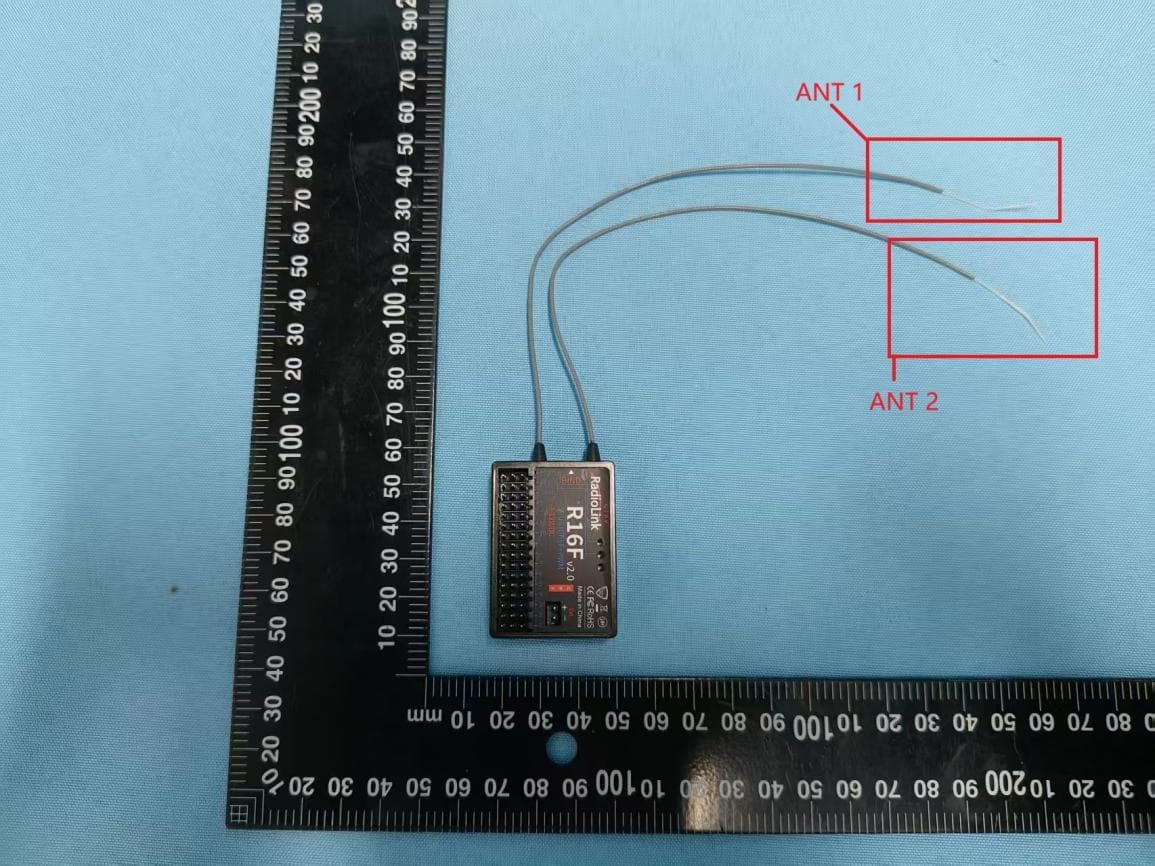
U2BRECEIVERR16F
May 19, 2026Receiver
Equipment Class
DSS - Part 15 Spread Spectrum TransmitterU2BRL039RECEIVER
Apr 16, 2024Receiver
Equipment Class
DSS - Part 15 Spread Spectrum Transmitter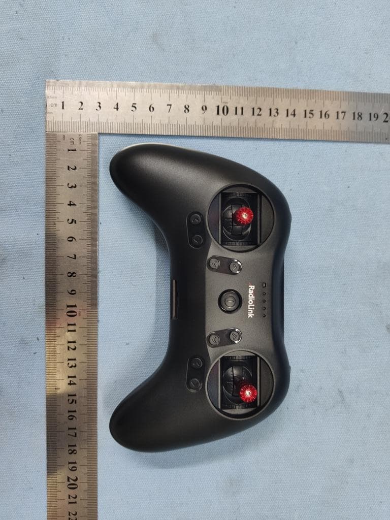
U2BRL039T8S
Mar 02, 2020Radio control
Equipment Class
DSS - Part 15 Spread Spectrum Transmitter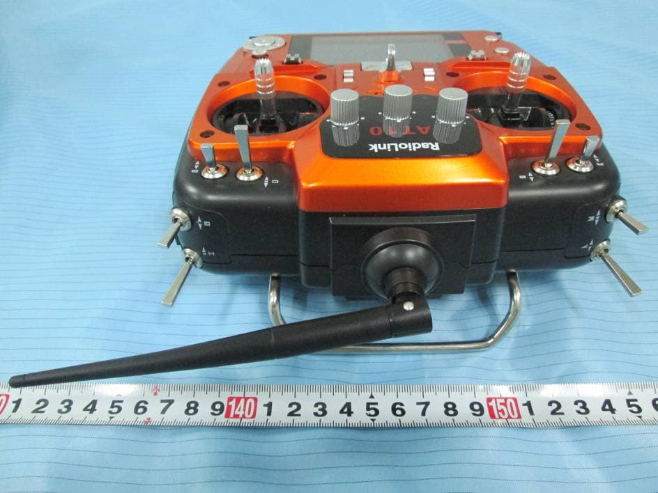
U2BRL039AT10
Sep 12, 2014Remote control
Equipment Class
DTS - Digital Transmission System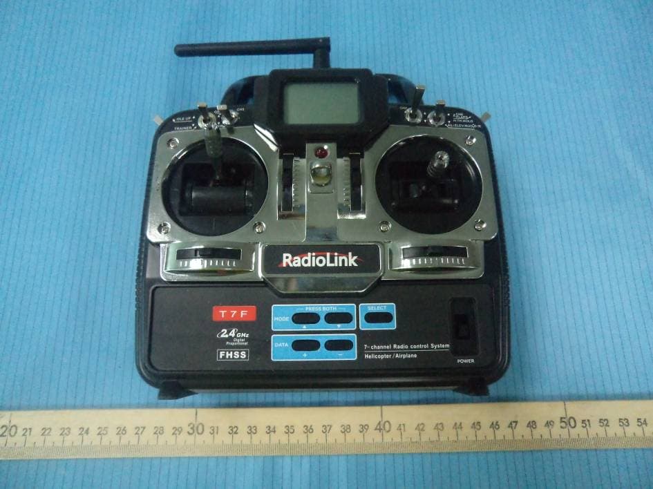
U2BRL037T001A
Jun 01, 20122.4G Digital Proportional R/C System
Equipment Class
DXX - Part 15 Low Power Communication Device Transmitter