U2C-FMPWR-2-32.4GHz TOUCHPOINT
Outsite Networks, Inc.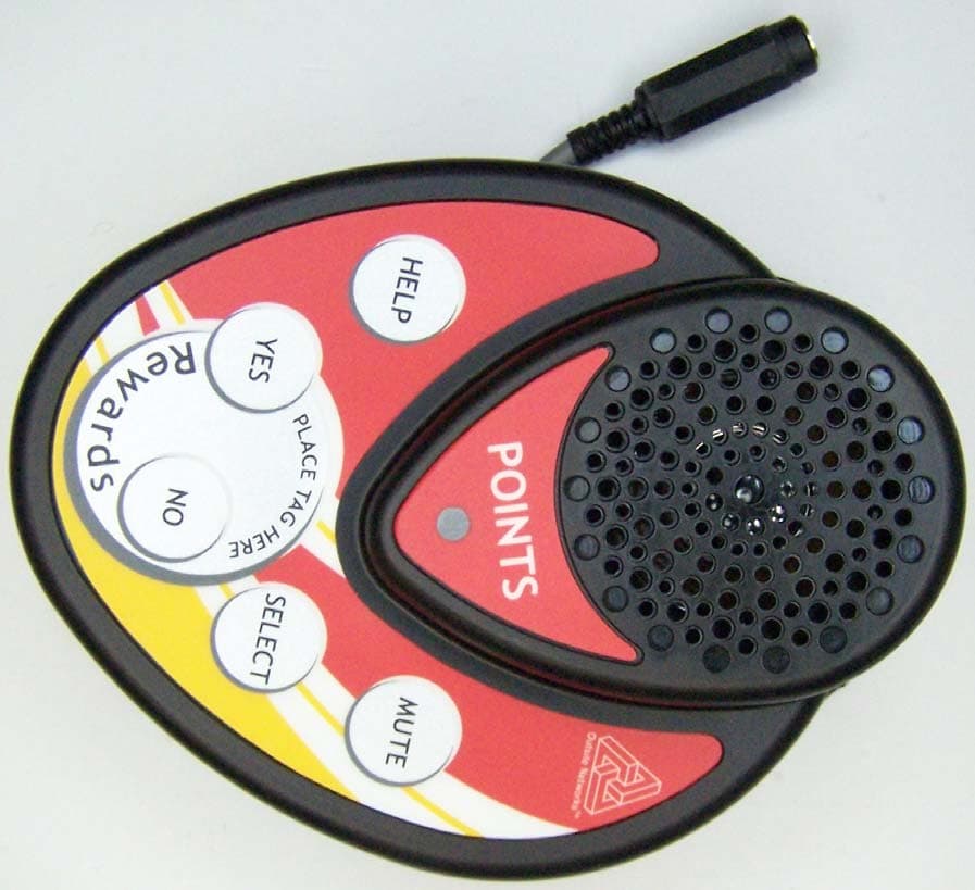
Click to zoom
Application Details
- Equipment Class
- DTS - Digital Transmission System
- Date of Grant
- Mar 07, 2007
- Application Purpose
- Original Equipment
- Date of Application
- Mar 07, 2007
- Equipment Note
- 2.4GHz TOUCHPOINT
- Frequency Range
- 2405.00000000 - 2480.00000000
- Company
- Outsite Networks, Inc.
- Country
- United States
Documents & Files
Document Text
Text extracted from the exhibit documents filed with the FCC. Open a document above to read the original.
Users Manual
Outsite Networks, Inc. 4855 Brookside Court Norfolk, VA 23502 Office: (757) 853-3000 Fax: (757) 853-3089 In-Touch Loyalty Marketing System Dispenser TouchPoint Unit Installation Manual Includes important information for the installation of TouchPoint units. Version 3.1 November 2006 Model FMPWR-2 Outsite Networks, Inc. Dispenser TouchPoint Unit Installation Manual Version 3.1 November 2006 Model FMPWR-2 Outsite Networks, Inc. 4855 Brookside Court Norfolk, VA 23502 Office: (757) 853-3000 Fax: (757) 853-3089 Copyright © 2006 Outsite Networks, Inc.™ All rights reserved. Outsite Networks, Inc. created this document. No part of this publication may be reproduced, stored in a retrieval system, modified, or transmitted in any form or by any means (electronic, mechanical, photocopying, recording or otherwise) without the express, prior written consent of the Outsite Networks, Inc. Changes or modifications not expressly approved by the party responsible for compliance could void the user’s authority to operate the equipment. NOTE: This equipment has been tested and found to comply with the limits for a Class A digital device, pursuant to part 15 of the FCC Rules. These limits are designed to provide reasonable protection against harmful interference when the equipment is operated in a commercial environment. This equipment generates, uses, and can radiate radio frequency energy and, if not installed and used in accordance with the instruction manual, may cause harmful interference to radio communications. Operation of this equipment in a residential area is likely to cause harmful interference in which case the user will be required to correct the interference at his own expense. This Class A digital apparatus complies with Canadian ICES-003. Cet appareil numérique de la classe A est conforme à la norme NMB-003 du Canada. Outsite Networks, Inc. Dispenser TouchPoint Unit Installation Manual Version 3.1 November 2006 Model FMPWR-2 Outsite Networks, Inc. 4855 Brookside Court Norfolk, VA 23502 Office: (757) 853-3000 Fax: (757) 853-3089 Dispenser TouchPoint Unit Installation Manual Contents Section Page PagePage Page 1 Electrical Connection Specifications 1 11 1 2 Physical and Power Specifications 1 11 1 3 Site Preparation 2 22 2 4 Secure Working Area 2 22 2 5 Turn Dispenser A\C Power Off 3 33 3 6 Prepare to Mount the Dispenser TouchPoint Unit 3 33 3 7 Connect Power 4 44 4 8 Connect the TouchPoint to the Dispenser 5 55 5 9 Enter Programming Mode 5 55 5 10 Program the Volume Level 6 66 6 11 Program the Fueling Position 6 66 6 12 Test the Dispenser TouchPoint Units 7 77 7 13 Post Installation 7 77 7 Limited Warranty 8 88 8 Gasoline Dispensing and Service Stations Diagram 9 99 9 Dispenser TouchPoint Unit Drilling Template Outsite Networks, Inc. Dispenser TouchPoint Unit Installation Manual Version 3.1 November 2006 Model FMPWR-2 Outsite Networks, Inc. 4855 Brookside Court Norfolk, VA 23502 Office: (757) 853-3000 Fax: (757) 853-3089 Page 1 of 9 1. Electrical Connection Specifications 1.1 Read this guide completely prior to installing the Dispenser TouchPoint Unit. 1.2 All electrical connections must comply with the following: o Equipment must be installed and used in accordance with the National Electric Code (NEC), and the National Fire Protection Association (NFPA) – Automotive and Marine Service Station Code. 1.3 Equipment must be installed in compliance with instructions set forth in this manual. 1.4 This manual contains wiring diagrams, drawings, and photographs to assist in the proper installation of the In-Touch System equipment. Any questions regarding this manual or the proper installation of the TouchPoint Unit should be addressed to the Service department of Outsite Networks, Inc. at 800-371-1118. 2. Physical and Power Specifications 2.1 Dispenser TouchPoint AC to DC Power Supply 2.1.1 Physical Dimensions: Height 1 ½” Width 2” Length 4 ½” Weight 2 lbs. 2. 1.2 Power Requirements: Single Phase 120VAC / 50-60Hz .6 Amps @ 120VAC .125 Amps (typical value) 2.1.3 Operating Environment: Rain Proof Enclosure Minimum Temperature -20°C ambient Maximum Temperature +40°C ambient 2.2 Dispenser TouchPoint Physical and Power Specifications 2.2.1 Physical Dimensions: Height 5 ¼” Width 4” Length 2” Weight 1 lbs. 2.2.2 Power Requirements: 12VDC .5 Amps @ 12VDC .25 Amps (typical value) 2.2.3 Operating Environment: Rain Proof Enclosure Outsite Networks, Inc. Dispenser TouchPoint Unit Installation Manual Version 3.1 November 2006 Model FMPWR-2 Outsite Networks, Inc. 4855 Brookside Court Norfolk, VA 23502 Office: (757) 853-3000 Fax: (757) 853-3089 Page 2 of 9 Minimum Temperature -20°C ambient Maximum Temperature +40°C ambient 3. Site Preparation 3.1 Installation must comply with the National Electric Code, the National Fire Protection Association codes and all applicable state and local codes. 3.2 Follow all safety precautions appropriate to working at locations where flammable liquids are stored; refer to Appendix A. 3.3 The site must be equipped with electrical service to meet the requirements of the installation instructions. 3.4 Supplied Materials • TouchPoint Unit • TouchPoint AC to DC Power Supply • AC Adaptor Cable • 10-32 Bolts (for mounting) • Lock Nuts • Template 3.5 List of recommended tools • Tape measure • ¼” drill bit • ½” drill bit • Manual hand or low speed pneumatic drill • 9” Lineman’s pliers or slip joint pliers 3.6 The TouchPoint unit can be mounted in several positions on the front panel of the dispenser’s electronic cabinet head. 3.7 Before mounting, ensure that there are no electronic components on the interior of the electronic cabinet door where the unit is being mounted and that mounting the TouchPoint unit does not obstruct future maintenance of the fuel dispenser. Mount the unit above the dispenser’s vapor barrier. 3.8 The TouchPoint power supply is connected to the dispenser AC power. The TouchPoint power supply converts AC power to DC power. 4. Secure Working Area 4.1 Before working on t…
Text truncated - open the document above for the full version.
Cover Letter(s)
Outsite Networks, Inc. 4855 Brookside Court Norfolk, VA 23502 phone: (757) 853-3000 fax: (757) 853-3089 www.outsitenetworks.com February 28, 2007 MET Laboratories, Inc. 914 West Patapsco Avenue Baltimore, MD 21230 RE: Confidentiality Request For EUT: TOUCH POINT and FCC ID# U2C-FMPWR-2-3 To Whom It May Concern: This letter serves as an official request for confidentiality under FCC Rule Section 0.459. We have requested that the schematic diagram, block diagram and operational/technical description documents required to be submitted with this application be withheld from public review. These documents are company proprietary information that could never get into the possession of our competition. Please contact me if there is any information you may need. Sincerely, Mr. Anton Bakker President & CEO Outsite Networks, Inc.
ID Label/Location Info
Materials: Polyester-2 mil-Gloss White Overlaminate: LexSaver® 5 mil velvet (UL) Ink Colors: Black FCC Label Here IC Label Here
ID Label/Location Info
FCCID: U2C-FMPWR-2-3 This device complies with Part 15 of FCC rules. Operation is subject to the following two conditions: 1) this device may not cause harmful interference and, 2) this device must accept any interference received, including interference that may cause undesired operation. 6944A-FMPWR23 This Class A digital apparatus complies with Canadian ICES-003. Cet appareil numérique de la classe A est conforme à la norme NMB-003 du Canada.
Test Report
MET Laboratories, Inc. Safety Certification - EMI - Telecom Environmental Simulation 914 WEST PATAPSCO AVENUE ! BALTIMORE, MARYLAND 21230-3432 ! PHONE (410) 354-3300 ! FAX (410) 354-3313 The Nation’s First Licensed Nationally Recognized Testing Laboratory March 8, 2007 Outsite Networks, Inc. 4855 Brookside Court Norfolk, VA 23502 Dear Benjamin Raydo, Enclosed is the EMC test report for compliance testing of the Outsite Networks, Inc., Touchpoint IAD02 as tested to the requirements of Title 47 of the CFR, Ch. 1 (10-1-03 ed.), Part 15, Subpart C. Thank you for using the services of MET Laboratories, Inc. If you have any questions regarding these results or if MET can be of further service to you, please feel free to contact me. Sincerely yours, MET LABORATORIES, INC. Samantha Sharbonda Documentation Department Reference: (\Outsite Networks, Inc.\EMC21023-FCC247) Certificates and reports shall not be reproduced except in full, without the written permission of MET Laboratories, Inc. While use of the National Voluntary Laboratory Accreditation Program (NVLAP) letters or the NVLAP Logo, the Standards Council of Canada Logo, or the Nationally Recognized Testing Laboratory (NRTL) Letters in this report reflects MET Accreditation under these programs, these letters, logo, or statements do not claim product endorsement by NVLAP or any Agency of the U.S. Government. This letter of transmittal is not a part of the attached report. Outsite Networks, Inc. Touchpoint IAD02 CFR Title 47, Part 15, Subpart C MET Report: EMC21023-FCC247 © 2007, MET Laboratories, Inc. Page i of ix Electromagnetic Compatibility Test Report for the Outsite Networks, Inc. Touchpoint IAD02 Verified under the FCC Certification Rules contained in Title 47 of the CFR, Part 15.247, Subpart C for Intentional Radiators MET Report: EMC21023-FCC247 March 8, 2007 Prepared For: Outsite Networks, Inc. 4855 Brookside Court Norfolk, VA 23502 Prepared By: MET Laboratories, Inc. 914 W. Patapsco Avenue Baltimore, Maryland 21230 Outsite Networks, Inc. Touchpoint IAD02 CFR Title 47, Part 15, Subpart C MET Report: EMC21023-FCC247 © 2007, MET Laboratories, Inc. Page ii of ix Electromagnetic Compatibility Test Report for the Outsite Networks, Inc. Touchpoint IAD02 Tested Under the FCC Certification Rules contained in Title 47 of the CFR, Part 15.247, Subpart C for Intentional Radiators Len Knight, Project Engineer Samantha Sharbonda Electromagnetic Compatibility Lab Documentation Department Engineering Statement: The measurements shown in this report were made in accordance with the procedures indicated, and the emissions from this equipment were found to be within the limits applicable. I assume full responsibility for the accuracy and completeness of these measurements, and for the qualifications of all persons taking them. It is further stated that upon the basis of the measurements made, the equipment tested is capable of operation in accordance with the requirements of Part 15.407, of the FCC Rules under normal use and maintenance. Kevin Mehaffey, Manager Electromagnetic Compatibility Lab Outsite Networks, Inc. Touchpoint IAD02 CFR Title 47, Part 15, Subpart C MET Report: EMC21023-FCC247 © 2007, MET Laboratories, Inc. Page iii of ix Report Status Sheet Revision Report Date Reason for Revision ∅ February 1, 2007 Initial Issue. 1 March 8, 2007 Editorial Corrections per TCB Technical Request. Outsite Networks, Inc. Table of Contents Touchpoint IAD02 CFR Title 47, Part 15, Subpart C MET Report: EMC21023-FCC247 © 2007, MET Laboratories, Inc. Page iv of ix Table of Contents I. Executive Summary .................................................................................................................................................1 A. Purpose of Test ...................................................................................................................................................2 B. Executive Summary ............................................................................................................................................2 II. Equipment Configuration .......................................................................................................................................3 A. Overview.............................................................................................................................................................4 B. References...........................................................................................................................................................5 C. Test Site ..............................................................................................................................................................5 D. Description of Test Sample.................................................................................................................................5 E. Equipment Configuration....................................................................................................................................6 F. Support Equipment .............................................................................................................................................6 G. Ports and Cabling Information ............................................................................................................................7 H. Mode of Operation..............................................................................................................................................7 I. Modifications ......................................................................................................................................................7 a) Modifications to EUT....................................................................................................................7 b) Modifications to Test Standard..............................................................................................…
Text truncated - open the document above for the full version.
Contact Information
Applicant
Chuck Mooring(VP of Engineering)
Test Firm
MET Laboratories, Inc.Kevin Mehaffey
Technical Specifications
| # | Rule Parts | Frequency Range | Power Output |
|---|---|---|---|
| 1 | 15C | 2.40 GHz - 2.48 GHz | 91.50 mW |
Other Applications from Outsite Networks, Inc.
U2C-ATB-2015
Nov 10, 2015Tap Beacon
Equipment Class
DTS - Digital Transmission System
U2C-APT-2014
Jul 30, 2014AllPoints Touch Printer (APT)
Equipment Class
DXX - Part 15 Low Power Communication Device Transmitter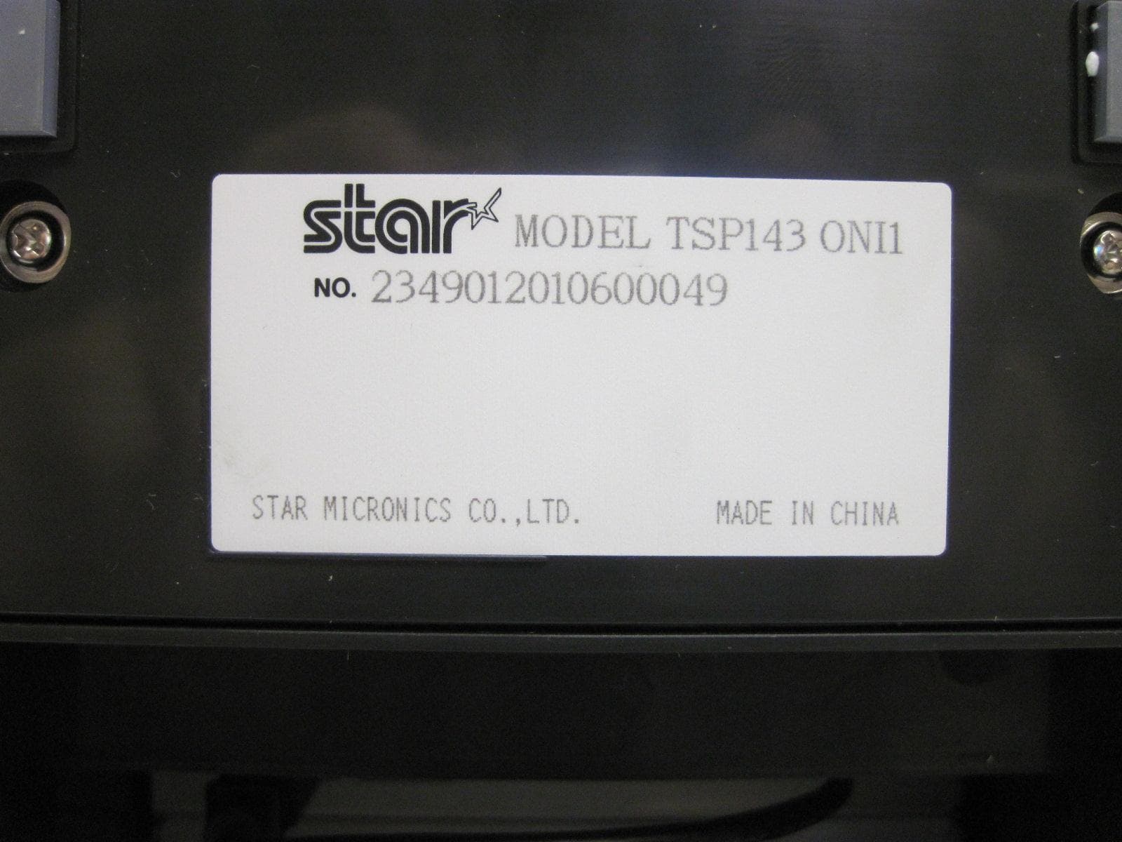
U2C-APX-2012
Dec 10, 2012All Points Printer
Equipment Class
DXX - Part 15 Low Power Communication Device Transmitter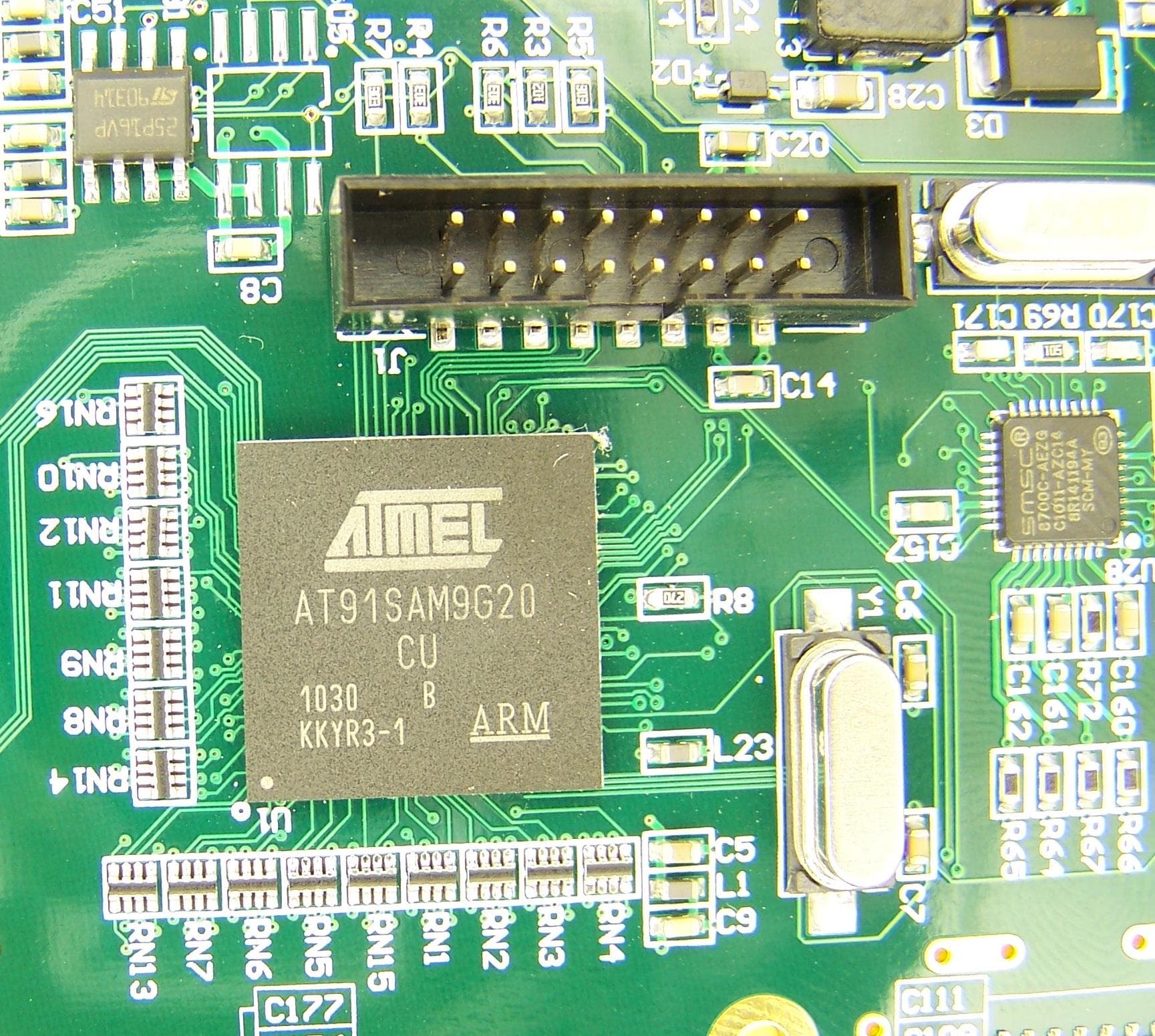
U2C-AIO-2011
Jan 17, 2012All In One Printer
Equipment Class
DXX - Part 15 Low Power Communication Device Transmitter