U2Z45602-3Dimmer Lamp Module
Sheenway Asia Ltd.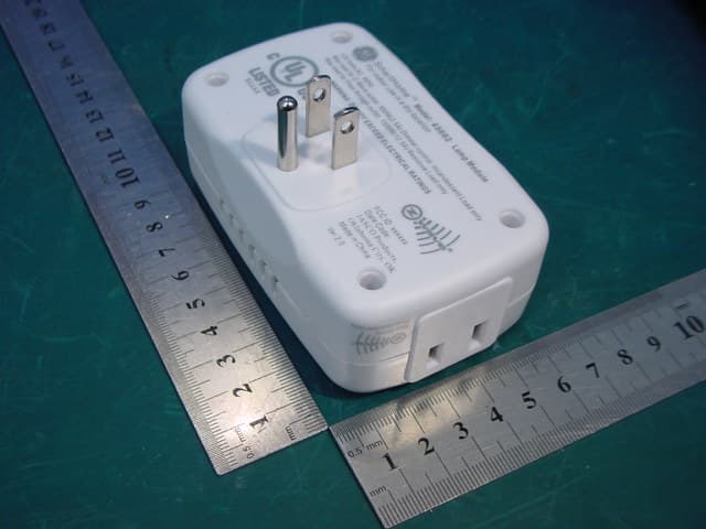
Click to zoom
Application Details
- Equipment Class
- DXX - Part 15 Low Power Communication Device Transmitter
- Date of Grant
- Apr 22, 2007
- Application Purpose
- Original Equipment
- Date of Application
- Apr 22, 2007
- Equipment Note
- Dimmer Lamp Module
- Frequency Range
- 908.42000000 - 908.42000000
- Company
- Sheenway Asia Ltd.
- Country
- China
Documents & Files
Document Text
Text extracted from the exhibit documents filed with the FCC. Open a document above to read the original.
Users Manual
45602 Instructions, Revision a.5 4/4/2007 6:26:10 PM Page 1 of 4 45602 Z-Wave, RF Controlled, 300W, 120 VAC, Plug-In Lamp Module R Add callouts for Z-Wave and Pass Through outlets Thank you for your purchase of a GE SmartHome™ Z-Wave ® control device. Z-Wave technology is designed to automate lighting/home control and provide easy remote operation of all your Z-wave enabled devices. The GE Z- Wave product family includes a variety of devices to enable and control lighting in your home. It is up to you whether you want to control one room or your entire house and whether you want to do it all now or start with one room and add more over time. This module is one component of a Z-Wave ® control system and is designed to work with all other Z-Wave enabled devices in a home control network. It will also act as a wireless repeater to insure that commands intended for another device in the network are received, thereby extending the range of the wireless controller. Z-Wave devices of other types and brands can be added to the system and will also act as range extenders if they support this function of repeating the signal received to other nodes in the system. The incandescent lighting plugged into the Z-Wave controlled outlet on this module must not exceed 300 watts. Plugging a non-resistive load such as fluorescent lighting or a device with a motor may result in damage to the Lamp Module and will void the warranty. There are no user serviceable parts in this unit. Key Features • One Z-wave controlled AC outlet for standard incandescent lighting o Remote ON/OFF and Brightness control via the Z-Wave controller o Manual ON/OFF and Brightness control with the front panel pushbutton • One Always-ON pass-through AC outlet • Space efficient design o Does not block the 2 nd outlet in a duplex wall receptacle o Plugs and cords for connected devices route to the side allowing close placement of furniture Basic Operation Manual Control The Front Panel Pushbutton on the 45602 Lamp Module allows the user to: 1. Manually turn the connected lighting ON/OFF by pressing the button. • This is a toggle switch; if the light is OFF, pressing the button turns the light ON and vice versa. 45602 Instructions, Revision a.5 4/4/2007 6:26:10 PM Page 2 of 4 2. Adjust the brightness level of the connected lighting by pressing and holding the button. Release the button when the desired level is attained. • This is also a toggle function. The lighting will dim until the minimum level is attained or the button is released. The next time the button is pressed and held, the level will increase until the maximum level is attained or the button is released. 3. Include or exclude the module from the Z-Wave home control network. • Refer to the instructions for your primary controller to access the setup function and include or exclude devices. • When prompted by your primary controller, tap the button. • The primary controller should indicate that the action was successful. If the controller indicates the action was unsuccessful, please repeat the procedure. • Once the module is part of the network, the same basic procedure is used to add the module to groups or scenes. Refer to the primary controller’s instructions for details. Please Note: After a power failure, the module defaults to OFF. The following Advanced Operation parameters require that you have an advanced controller like the GE model 45601 LCD remote. Advanced remotes from other manufacturers may also be able to change these settings; however, basic remotes do not have this capability. All On/All Off Depending upon your primary controller, the 45602 lamp module can be set to respond to ALL ON and ALL OFF commands in up to four different ways. Some controllers may not be able to change the response from its default setting. Please refer to your controller’s instructions for information on whether or not it supports the configuration function and if so, how to change this setting. The four possible responses are: • It will respond to ALL ON and the ALL OFF command (default). • It will not respond to ALL ON or ALL OFF commands. • It will respond to the ALL OFF command but will not respond to the ALL ON command. • It will respond to the ALL ON command but will not respond to the ALL OFF command. Dim Rate Adjustments Both the number of steps (or levels) that the dimmer will change and the timing of the steps can be modified to suit personal preferences. The timing of the steps can be adjusted in 10 millisecond intervals. As an example, the default setting for parameter 8 is “3”. This means that the lighting level will change every 30 milliseconds when the Dim Command is received. A value of 255 would mean that the level would change every 2.55 seconds. Combined, the two parameters allow dim rate adjustments from 10 milliseconds to 4.2 minutes to go from maximum-to-minimum or minimum-to-maximum brightness levels. 1. When Receiving a Z-Wave Dim Command • Parameter 7 (number of steps or levels) • Parameter 8 (timing of the steps) • Length: 1 Byte • Valid Values: Parameter 7 (default = 1) Valid Values: 1-99 Parameter 8 (default = 3) Valid Values: 1-255 2. Manual Control Dimming (pressing the Dimmer’s rocker) • Parameter 9 (number of steps or levels) • Parameter 10 (timing of the steps) • Length: 1 Byte • Valid Values: Parameter 9 (default = 1) Valid Values: 1-99 Parameter 10 (default = 3) Valid Values: 1-255 45602 Instructions, Revision a.5 4/4/2007 6:26:10 PM Page 3 of 4 3. When Receiving an All-On or All-Off Command • Parameter 11 (number of steps or levels) • Parameter 12 (timing of the steps) • Length: 1 Byte • Valid Values: Parameter 11 (default = 1) Valid Values: 1-99 Parameter 12 (default = 3) Valid Values: 1-255 Ignore Start Level When Receiving Dim Commands Please note: Every “Dim” command from your remote controller includes a start level embedded in it. The 45602 can be set to ignore the start level that is part of the dim command. Setting parameter 5 to a value of…
Text truncated - open the document above for the full version.
Cover Letter(s)
Sheenway Asia Ltd Room 1313, 13/F, Austin Tower, Tsim Sha Tsui, Kowloon. Tel: (86-755)82374246 Fax: (86-755)82375277 Email: [email protected] ; [email protected] Federal Communications Commission 7435 Okland Mills Road Columbia, MD 21046 Genelmen: This letter is to comply with section 0.457(d)(2)(i) pertaining to confidential material. Sheenway Asia Ltd would like the following documents regarding this submission for FCC ID: U2Z45602-3 to be kept confidential. 1. schematics 2. block diagram the above documents contains trade secrets or technical data, which would customarily be guarded from competitors. We do not want the documents to be accessible to general public. If you have any questions regarding the authorization, please don’t hesitate to contact us. Thank you! Sincerely yours, --------------------------------------------------- Project Engineer company: Sheenway Asia Ltd Tel: (86-755)82374246 Fax: (86-755)82375277 E-mail: [email protected] ; [email protected]
External Photos
External Photo 1 Photo 1 Appearance of EUT (45603) Photo 2 Appearance of EUT (45603) External Photo 2 Photo 3 Appearance of EUT (45602) Photo 4 Appearance of EUT (45602)
Internal Photos
Internal Photo 1 Photo 1 Inside of EUT (45603) Photo 2 Inside of EUT (45603) Internal Photo 2 Photo 3 Inside of EUT (45603) Photo 4 Inside of EUT (45603) Internal Photo 3 Photo 5 Inside of EUT (45603) Photo 6 Inside of EUT (45602) Internal Photo 4 Photo 7 Inside of EUT (45602) Photo 8 Inside of EUT (45602) Internal Photo 5 Photo 9 Inside of EUT (45602) Photo 10 Inside of EUT (45602)
Operational Description
Operation description: 45602(ZDP100)— Please refer to hardware block diagram: 1) Plug the unit into the AC 120V,60Hz line 2) AC power will be rectified and regulated to DC 6.8 V and DC 3.3 V for TRIAC control and CPU power supply respectively. 3) Plug the appliance loading to the Z-wave controllable AC outlet. 4) Press the push button on the unit to turn the appliance ON/OFF. Press and hold the push button on the unit to turn the appliance to bright/dim. 5) Load sense is the circuit that will sense the availability of a load. The relay will be turned on from off state when a load such as a bulb is plugged into the AC outlet. 45603(ZRP100) and 45605(ZRP150)—Please refer to hardware block diagram: 1) Plug the unit into the AC 120V, 60Hz line 2) AC power will be rectified and regulated to DC 12V and 3.3V for CONTROL and CPU power supply respectively. 3) Plug the appliance loading to the Z-wave controllable AC outlet 4) Press the push button on the unit to turn the relay ON/OFF to control the appliance loading to ON/OFF. You may use remote controller to do the same operation. 5) Load sense is the circuit that will sense the availability of a load. The relay will be turned on from off state when a load such as a light bulb is plugged into the AC outlet.
Test Report
Report No.: WT078000354 Page 1/40 EMC TEST REPORT For Dimmer lamp module & Relay fluorescent light appliance module Model Number: ZDP100 45602 ZRP100 45603 FCC ID: U2Z45602-3 Report Number : WT078000354 Test Laboratory : Shenzhen Academy of Metrology and Quality Inspection EMC Laboratory Guangdong EMC Compliance Test Center Site Location : Bldg. of Metrology &Quality Inspection, Longzhu Road, Shenzhen, Guangdong, China Tel : 0086-755-26941637, 26941529, 26941531 Fax : 0086-755-26941545 Email : [email protected] Report No.: WT078000354 Page 2/40 TABLE OF CONTENTS TEST REPORT DECLARATION ........................................................................................................3 1. TEST RESULTS SUMMARY ...................................................................................................4 2. GENERAL INFORMATION ....................................................................................................5 2.1. Report information ............................................................................................................5 2.2. Laboratory Accreditation and Relationship to Customer .................................................5 2.3. Measurement Uncertainty .................................................................................................6 3. PRODUCT DESCRIPTION ......................................................................................................6 3.1. EUT Description ...............................................................................................................6 3.2. Related Submittal(s) / Grant (s) ........................................................................................6 3.3. Block Diagram of EUT Configuration..............................................................................7 3.4. Operating Condition of EUT ............................................................................................7 3.5. Special Accessories...........................................................................................................7 3.6. Equipment Modifications..................................................................................................7 3.7. Support Equipment List ....................................................................................................7 3.8. Test Conditions .................................................................................................................7 4. TEST EQUIPMENT USED .......................................................................................................8 4.1. Test Equipment Used to Measure Conducted Disturbance ..............................................8 4.2. Test Equipment Used to Measure Radiated Disturbance and bandwidth.........................8 5. CONDUCTED DISTURBANCE TEST ....................................................................................9 5.1. Test Standard and Limit ....................................................................................................9 5.2. Test Procedure ..................................................................................................................9 5.3. Test Arrangement..............................................................................................................9 5.4. Test Data ...........................................................................................................................9 6. RADIATED DISTURBANCE TEST ......................................................................................18 6.1. Test Standard and Limit ..................................................................................................18 6.2. Test Procedure ................................................................................................................18 6.3. Test Arrangement............................................................................................................18 6.4. Test Data .........................................................................................................................19 7. OCCUPIED BANDWIDTH .....................................................................................................24 7.1. Test Standard and Limit ..................................................................................................24 7.2. Test Procedure ................................................................................................................24 7.3. Test Arrangement............................................................................................................24 7.4. Test Data .........................................................................................................................24 8. BAND EDGE .............................................................................................................................26 8.1. Test Standard and Limit ..................................................................................................26 8.2. Band Edge FCC 15.249(d) Limit ....................................................................................26 8.3. Test Procedure ................................................................................................................26 8.4. Test Arrangement............................................................................................................26 8.5. Test Data .........................................................................................................................26 9. ANTENNA REQUIREMENT .................................................................................................28 APPENDIX I TEST PHOTO...............................................................................................................29 APPENDIX II EUT PHOTO ...............................................................................................................33 Report No.: WT078000354 …
Text truncated - open the document above for the full version.
Test Setup Photos
Test Photo 1 Photo 1 Conducted Emission Test (45603) Photo 2 Conducted Emission Test (45603) Test Photo 2 Photo 3 Radiated Emission Test (45603) Photo 4 Radiated Emission Test (45603) Test Photo 3 Photo 5 Radiated Emission Test (45603) Photo 6 Radiated Emission Test (45603)
Contact Information
Applicant
Francois Suignard-Ravalec
Technical Contact
ShenZhen AcademyPeter Lin
[email protected]86-755-2694-1599
Bld. of Metrelogy, Longzhu Rd. · Nanshan, Shenzhen · China
Test Firm
Shenzhen Academy of Metrology & Quality InspectionPeter Lin
Technical Specifications
| # | Rule Parts | Frequency Range | Power Output |
|---|---|---|---|
| 1 | 15C | 908.42 MHz - 908.42 MHz | - |
Other Applications from Sheenway Asia Ltd.
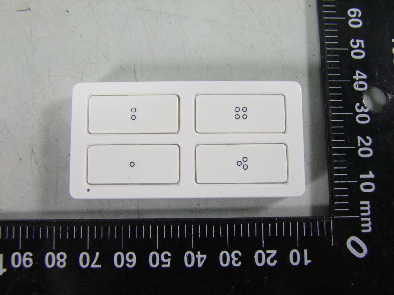
U2ZZW5314
Oct 28, 2020Z-Wave 700s 4-Button Simple Controller
Equipment Class
DXT - Part 15 Low Power Transceiver, Rx Verified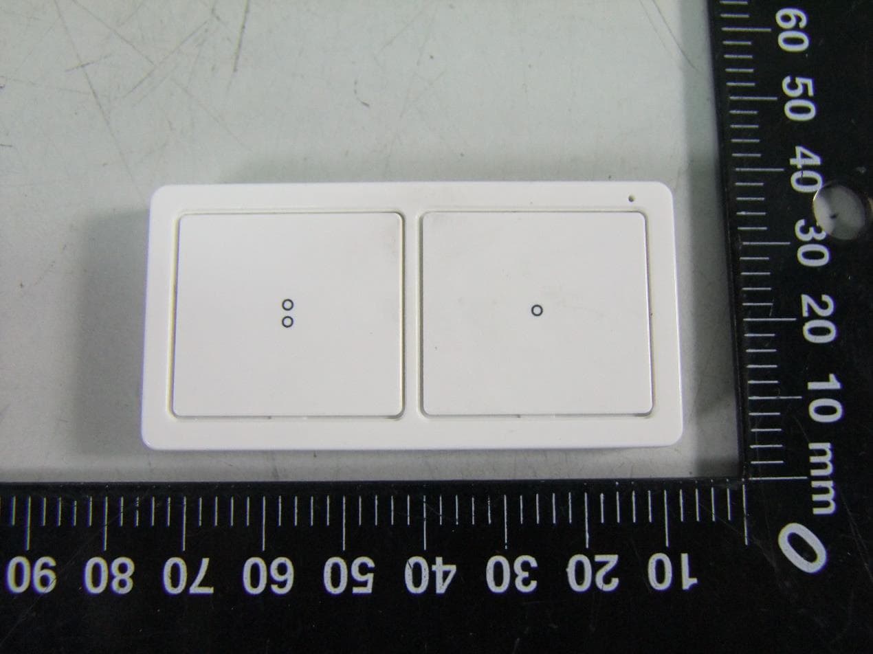
U2ZZW5313
Oct 28, 2020Z-Wave 700s 2-Button Simple Controller
Equipment Class
DXT - Part 15 Low Power Transceiver, Rx Verified
U2ZZW6309
Oct 27, 2020Z-Wave 700s Water Leak Sensor
Equipment Class
DXT - Part 15 Low Power Transceiver, Rx Verified
U2ZZW3012
Oct 13, 2020Z-Wave 700s In-Wall No Neutral Dimmer
Equipment Class
DXT - Part 15 Low Power Transceiver, Rx Verified
U2ZZW3011DV
Oct 12, 2020Z-Wave In-Wall Toggle Dimmer 0-10V 120/277V
Equipment Class
DXT - Part 15 Low Power Transceiver, Rx Verified