U2ZZB3001Wireless relay
Sheenway Asia Ltd.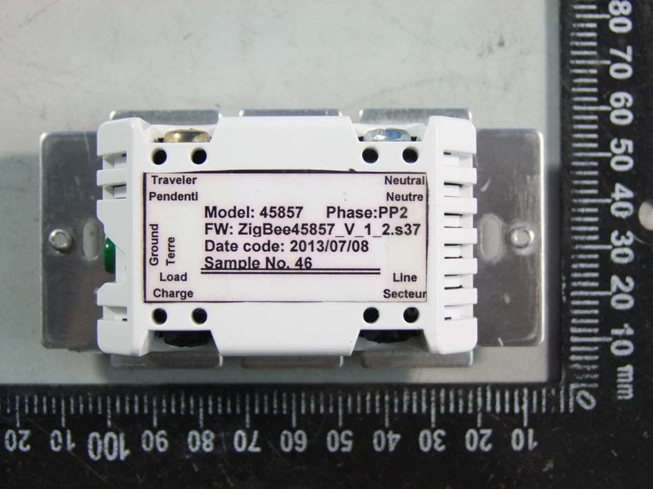
Click to zoom
Application Details
- Equipment Class
- DTS - Digital Transmission System
- Date of Grant
- Nov 26, 2013
- Application Purpose
- Original Equipment
- Date of Application
- Nov 26, 2013
- Equipment Note
- Wireless relay
- Frequency Range
- 2405.00000000 - 2480.00000000
- Company
- Sheenway Asia Ltd.
- Country
- China
Documents & Files
Document Text
Text extracted from the exhibit documents filed with the FCC. Open a document above to read the original.
Users Manual
ZB3001 (45857) ZigBee®, In‐Wall On/Off/Dimmer Switch Home Automation Standard Version 1.2 Compliant Introduction Thank you for your purchase of a Jasco ZigBee® control device. Jasco ZigBee lighting controls are designed to automate lighting/home control and provide easy remote operation of all your ZigBee enabled devices. The Jasco ZigBee product family includes a variety of devices to control lighting in your home. It is up to you whether you want to control one room or your entire house and whether you want to do it all now or start with one room and add more over time. This dimmer switch is designed for use with permanently installed lighting fixtures only. The switch has been optimized for use with incandescent lighting as well as with most dimmable CFL and LED bulbs. The maximum load ratings for this switch are 600W for incandescent bulbs and 150W for dimmable CFL and LED’s. Lighting controlled by this switch must not exceed these stated limits. NOTE: Actual performance of any CFL or LED will vary from bulb type to bulb type and among different manufacturers. It is important to note that only bulbs that have been designed as dimmable should be used on a dimmer. To find out if your bulb is dimmable, please check the package, the bulb itself,or call the bulb manufacturer directly. CAUTION ‐ To Reduce The Risk of Overheating and Possible Damage to Other Equipment, Do Not Install to Control a Motor‐Operated Appliance, A Fluorescent Lighting Fixture or a Transformer Supplied Appliance There are no user serviceable parts in this unit. ! Warning ! RISK OF FIRE RISK OF ELECTRICAL SHOCK RISK OF BURNS NOT FOR USE WITH MEDICAL OR LIFE SUPPORT EQUIPMENT ZigBee enabled devices should never be used to supply power to or control the On/Off status of medical and/ or life support equipment! WARNING: Controlling Appliances: Exercise extreme caution when using ZigBee devices to control appliances. Operation of the ZigBee device may be in a different room than the controlled appliance, also an unintentional activation may occur if the wrong button on the controller interface is pressed. ZigBee devices may automatically be powered on due to timed event programming. Depending upon the appliance, these unattended or unintentional operations could possibly result in a hazardous. 1. Do Not include ZigBee devices in Groups or Scenes if they control appliances. 2.Do Not use ZigBee devices to control electric heaters or any other appliances which may present a hazardous condition due to unattended or unintentional or automatic power on control. Key Features Turn ON/OFF or DIM lighting manually or remotely via the ZigBee controller Can be Included in multiple Groups and Scenes May be used in single pole installation or with up to two Jasco auxiliary switches in 2‐way, 3‐ way or 4‐way wiring configurations Works with Dimmable CFL/LED bulbs for improved energy efficiency Interchangeable Paddle switch: White & light almond paddle in package Over the Air updates – Once joined to your ZigBee network, the device can transparently receive updates through your ZigBee gateway Energy Monitoring – The device can report wattage (W) and kilowatt hours (kWh). Energy usage is monitored through the ZigBee Controller Interface Uses a standard, decora‐size wall plate for single gang installations (wall plate not included) Blue LED indicates switch location in a dark room (LED can be enabled/disabled manually) LED Status Indicator – Indicates device scanning during pairing process ZigBee HA 1.2 Certified for simple pairing and integrated home automation Screw Terminal installation; requires wiring connections for Line (Hot), Load, Neutral, and Ground. Traveler wire required for multi pole installation To change color of the switch 1. Lift the Air Gap tab at the base of the cover. 2. Push side tabs in on one side and then the other to release cover. Lift the cover up and off. 3. Simply put the new cover onto the switch by inserting the air gap and side tabs and snapping securely into place. Installation This switch may be used in new installations or to replace an existing wall switch. It may be used by itself for 2‐way control (one switch & one load), with one Jasco Auxiliary Switch for 3‐way control (two switches & one load) or with two Jasco Auxiliary switches for 4‐way control (three switches & one load). When used by itself for 2‐way control, please make sure that the screw terminal for the traveler wire is insulated (Do Not Remove the tape over the terminal if you are not using the traveler connection) WARNING ‐ SHOCK HAZARD Turn OFF the power to the branch circuit for the switch and lighting fixture at the service panel. All wiring connections must be made with the POWER OFF to avoid personal injury and/or damage to the switch. CONNECTIONS TWO‐WAY CONTROL SINGLE SWITCH WIRING USING ONE PRIMARY SWITCH THREE‐WAY CONTROL TWO SWITCH WIRING USING ONE PRIMARY AND ONE AUXILIARY SWITCH FOUR‐WAY CONTROL THREE SWITCH WIRING USING ONE PRIMARY AND TWO AUXILIARY SWITCHES Single, Dual and Triple Gang Boxes The metal plate surrounding the switch assembly is a heat sink. The maximum load rating (600W) is provided when installed in a single gang box with the full heat sink. Multiple dimmer switches may be installed in dual or triple gang boxes and, if necessary, one or both sides of the heat sink may be removed by bending it at the score lines. There is a corresponding reduction in the switch’s load rating when ganged. DO NOT exceed the following loads: CFL/LED RATING Incandescent RATING Number of Dimmers Heat Sink 150W 600W 1 Switch in Single Gang Box Full – No tabs removed 125W 500W 2 Switches in Double Gang Box One tab removed (Inner) 100W 400W 3 Switches in Triple Gang Box Both tabs removed Observe Important Wiring Information Important: This switch is rated for and intended to only be used with copper wire. The home’s electrical wires may be attached to the screw terminals or inserted into the holes in the back of the swit…
Text truncated - open the document above for the full version.
External Photos
External Photo
ID Label/Location Info
JASCO Products, Oklahoma City, OK www.jascoproducs.com Made in China / Fabriqué en Chine Pendentif Terre Secteur Neutral Neutre Charge Dimmer Switch Gradateur Model: ZB3001 (45857) Gradateur 120VAC/120 V c.a. Date Code For indoor use Pour utilisation intérieure uniquement Tighten terminal screws to 12 lbf-in Serrer les vis de borne à 12 lbf-po FCC ID: U2ZZB3001 IC: 6924A-ZB3001 VER 3.0d ZB 3001 60Hz 600W150W Dimmable CFL/LED 1331 PMS 430C Printing Type: Flexo O set Roto ZB3001 (45857) -1 Inclosure Art SIGN OR PDQ TYPE: PRODUCT MANAGER: VENDOR: CONTACT: Label Apron Card Brochure Flip Chart Product Marking SPECIAL NOTES: 10 / 25 / 2013 PRE Production APPROVED QC APPROVED If there are any changes on the art and/or dieline please let the designer know. Pad Printing Specification for Jasco Zigbee Product Jasco model no.: ZB3001(45857) 3MWZ Pour utilisation intérieure uniquement Indoor use only
Internal Photos
Internal Photo
RF Exposure Info
ZB3001(45857) MPE calculation FCC ID: U2ZZB3001 The maximum measured power output is: 15.6dBm The maximum antenna gain for integral antenna is: 1.1dBi The maximum permissible exposure is defined in 47 CFR 1.1310 with 1 mW/cm². The Transmitter is using external antennas that operate at 20 cm or more from nearby persons. The maximum permitted level is calculated using the general equation: S = P’ / 4πR² P’ = 15.6dBm+1.1dBi =16.7dBm=46.8mW R = 20cm π = 3.1416 Solving for S, the power density at 20 cm is: 0.093mW/cm²
Test Report
FCC TEST REPORT For In-wall dimmer Model Number: ZB3001(45857) FCC ID: U2ZZB3001 Report Number : WT138003204 Test Laboratory : Shenzhen Academy of Metrology and Quality Inspection National Digital Electronic Product Testing Center Site Location : No.4 TongFa Road, Xili Town, Nanshan District, Shenzhen, China Tel : 0086-755-86009898 Fax : 0086-755-86009898-31396 Web : www.smq.com.cn Report No.:WT138003204 Page 2 of 35 Test report declaration Applicant : SHEENWAY ASIA LTD. Address : Room1313, 13/F., AustinTower, 22-26AustinAvenu, TsimSha Tsui, Kowloon. Hong Kong. China Manufacturer : KONIG ELECTRONIC (HUIZHOU) LTD. Address : 2-Plant, East Lake Side, QingTang, Lian He Village, Shui Kou, Hui Cheng District, Huizhou, GuangDong, China. Factory : KONIG ELECTRONIC (HUIZHOU) LTD. Address : 2-Plant, East Lake Side, QingTang, Lian He Village, Shui Kou, Hui Cheng District, Huizhou, GuangDong, China. EUT Description : In-wall dimmer Model No : ZB3001(45857) FCC ID : U2ZZB3001 Test Standards: FCC Part 15 15.207, 15.209, 15.247 (2012) ANSI C63.4: 2009 The EUT described above is tested by Shenzhen Academy of Metrology and Quality Inspection EMC Laboratory to determine the maximum emissions from the EUT. Shenzhen Academy of Metrology and Quality Inspection EMC Laboratory is assumed full responsibility for the accuracy of the test results. The test data, data evaluation, test procedures, and equipment configurations shown in this report were made in accordance with the procedures given in ANSI C63.4 (2009) and the energy emitted by the sample EUT tested as described in this report is in compliance with FCC Rules Part 15.207, 15.209 and 15.247. The test report is valid for above tested sample only and shall not be reproduced in part without written approval of the laboratory. Project Engineer: Date: Nov.20,2013 (Chen Qichun) Nov.20,2013 Checked by: Date: (Yang Dongping) Nov.20,2013 Approved by: Date: (Lin Bin) Report No.:WT138003204 Page 3 of 35 TABLE OF CONTENTS TEST REPORT DECLARATION ........................................................................................................ 2 1. TEST RESULTS SUMMARY ................................................................................................... 5 2. GENERAL INFORMATION ...................................................................................................... 6 2.1. Report information .......................................................................................................... 6 2.2. Laboratory Accreditation and Relationship to Customer ......................................... 6 2.3. Measurement Uncertainty ............................................................................................. 7 3. PRODUCT DESCRIPTION ...................................................................................................... 8 3.1. EUT Description .............................................................................................................. 8 3.2. Related Submittal(s) / Grant (s) ................................................................................... 8 3.3. Block Diagram of EUT Configuration .......................................................................... 9 3.4. Operating Condition of EUT.......................................................................................... 9 3.5. Support Equipment List ............................................................................................... 10 3.6. Test Conditions ............................................................................................................. 10 3.7. Special Accessories ..................................................................................................... 10 3.8. Equipment Modifications ............................................................................................. 10 4. TEST EQUIPMENT USED ..................................................................................................... 11 5. 6DB BANDWIDTH MEASUREMENT ................................................................................... 12 5.1. Limits of 6dB Bandwidth Measurement .................................................................... 12 5.2. Test Procedure ............................................................................................................. 12 5.3. Test Setup ..................................................................................................................... 12 5.4. Test Data ....................................................................................................................... 13 6. MAXIMUM PEAK CONDUCTED OUTPUT POWER MEASUREMENT ........................ 15 6.1. Limits of Maximum Peak Conducted Output Power Measurement ..................... 15 6.2. Test Procedure ............................................................................................................. 15 6.3. Test Data ....................................................................................................................... 15 7. MAXIMUM POWER SPECTRAL DENSITY LEVEL MEASUREMENT .......................... 17 7.1. Limits of Maximum Power Spectral Density Level Measurement ........................ 17 7.2. Test Procedure ............................................................................................................. 17 7.3. Test Data ....................................................................................................................... 17 8. CONDUCTED BANDEDGE AND SPURIOUS MEASURMENT ...................................... 19 Report No.:WT138003204 Page 4 of 35 8.1. Limits of Conducted Band Edge and Spurious Measurement .............................. 19 8.2. Test Procedure ............................................................................................................. 19 8.3. Test Data .....................................................................................................................…
Text truncated - open the document above for the full version.
Test Setup Photos
Conducted Disturbance Radiated Disturbance
Contact Information
Applicant
Sammel Tung
Test Firm
Shenzhen Academy of Metrology & Quality InspectionPeter Lin
Technical Specifications
| # | Rule Parts | Frequency Range | Power Output |
|---|---|---|---|
| 1 | 15C | 2.40 GHz - 2.48 GHz | 36.50 mW |
Other Applications from Sheenway Asia Ltd.
U2ZZW5314
Oct 28, 2020Z-Wave 700s 4-Button Simple Controller
Equipment Class
DXT - Part 15 Low Power Transceiver, Rx Verified
U2ZZW5313
Oct 28, 2020Z-Wave 700s 2-Button Simple Controller
Equipment Class
DXT - Part 15 Low Power Transceiver, Rx Verified
U2ZZW6309
Oct 27, 2020Z-Wave 700s Water Leak Sensor
Equipment Class
DXT - Part 15 Low Power Transceiver, Rx Verified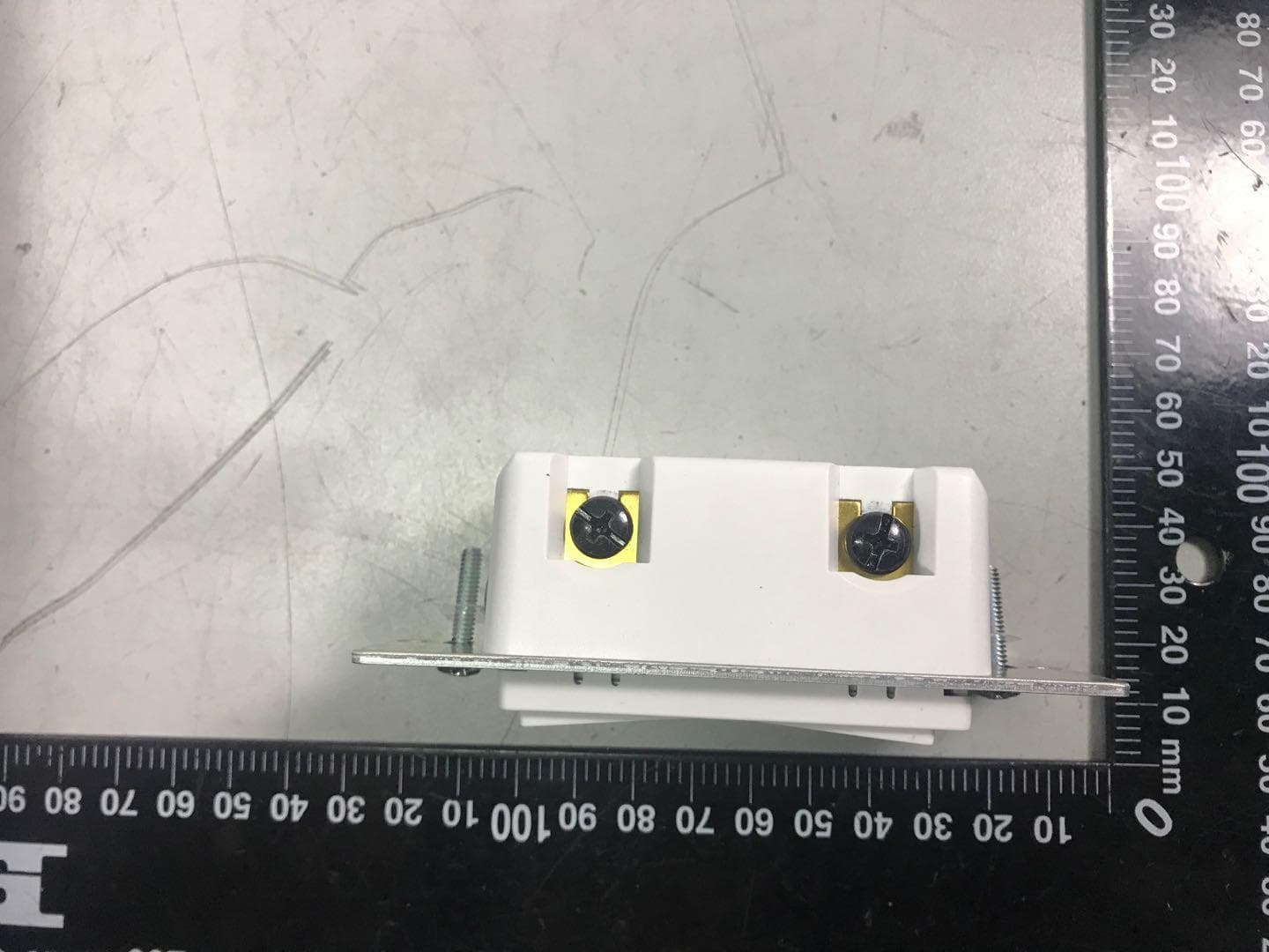
U2ZZW3012
Oct 13, 2020Z-Wave 700s In-Wall No Neutral Dimmer
Equipment Class
DXT - Part 15 Low Power Transceiver, Rx Verified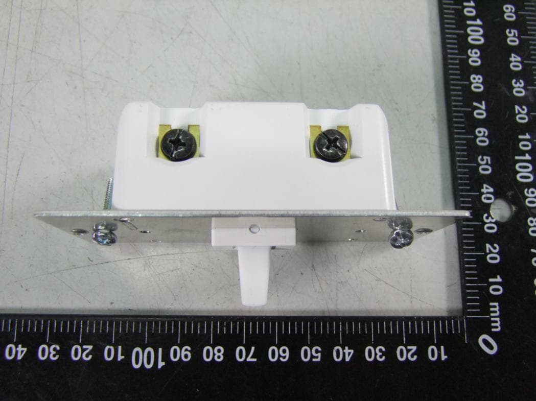
U2ZZW3011DV
Oct 12, 2020Z-Wave In-Wall Toggle Dimmer 0-10V 120/277V
Equipment Class
DXT - Part 15 Low Power Transceiver, Rx Verified