U2ZZW3007wireless relay
Sheenway Asia Ltd.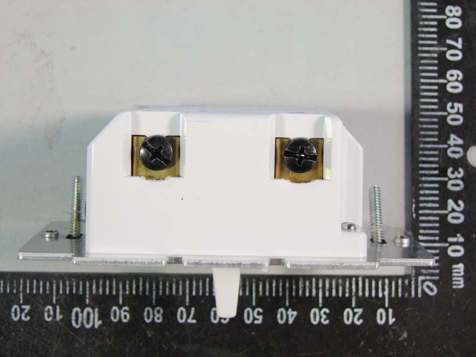
Click to zoom
Application Details
- Equipment Class
- DXT - Part 15 Low Power Transceiver, Rx Verified
- Date of Grant
- Sep 03, 2013
- Application Purpose
- Original Equipment
- Date of Application
- Sep 03, 2013
- Equipment Note
- wireless relay
- Frequency Range
- 908.40000000 - 908.40000000
- Company
- Sheenway Asia Ltd.
- Country
- China
Documents & Files
Document Text
Text extracted from the exhibit documents filed with the FCC. Open a document above to read the original.
Users Manual
Z-Wave ® Certified Wireless Lighting Control On/Off/Dim Dimmer Switch 45716_45717 ZW3007 Made in China Introduction: Thank you for your purchase of a Jasco Z-Wave® control device. Z-Wave technology is designed to automate lighting/home control and provide easy remote operation of all your Z-Wave enabled devices.The Jasco Z-Wave product family includes a variety of devices to control lighting in your home. It is up to you whether you want to control one room or your entire house and whether you want to do it all now or start with one room and add more over time. This dimmer is one component of a Z-Wave® control system and is designed to work with all other Z-Wave enabled devices in a home control network. It will also act as a wireless repeater to insure that commands intended for another device in the network are received, thereby extending the range of the wireless controller. Z-Wave devices of other types and brands can be added to the system and will also act as range extenders if they support this function of repeating the signal received to other nodes in the system. Air gap switch Dimmer switch This switch is designed for use only with permanently installed incandescent fixtures. Do not use it to control fluorescent lighting, transformer supplied lighting/appliances or receptacles. The incandescent lighting controlled by this dimmer switch must not exceed 600 watts. NOT FOR USE WITH MEDICAL OR LIFE SUPPORT EQUIPMENT Z-Wave enabled devices should never be used to supply power to or control the On/Off status of medical and/or life support equipment! This device is intended for installation in accordance with the National Electric Code and local regulations in the United States, or the Canadian Electrical Code and local regulations in Canada. If you are unsure or uncomfortable about performing this installation consult a qualified electrician. CAUTION RISK OF FIRE RISK OF ELECTRICAL SHOCK RISK OF BURNS WARNING Controlling Appliances: Exercise extreme caution when using Z-Wave devices to control appliances. Operation of the Z-Wave device may be in a different room than the controlled appliance, also an unintentional activation may occur if the wrong button on the remote is pressed. Z-Wave devices may automatically be powered on due to timed event programming. Depending upon the appliance, these unattended or unintentional operations could possibly result in a hazardous condition. For these reasons, we recommend the following: 1. Assign Z-Wave controlled appliances to device numbers 10 – 18 on the Jasco remote. The likelihood of unintentionally turning on the appliance will be reduced significantly because the “Shift” button will need to be pressed before pressing device numbers 10-18. 2. Z-Wave devices controlling appliances should be removed from “All” control setting. Instructions on how to do this are included in the manual for your Jasco remote. 3. Do Not include Z-Wave devices in Groups or Scenes if they control appliances. 4. Do Not use Z-Wave devices to control electric heaters or any other appliances which may present a hazardous condition due to unattended or unintentional or automatic power on control. 5. Double check programs for accuracy before using them. Wireless Range This device complies with the Z-Wave standard of open- air, line of sight transmission distances of 65 feet. Actual performance in a home depends on the number of walls between the remote controller and the destination device, the type of construction and the number of Z-Wave enabled devices installed in the control network. Every Z-Wave enabled device acts as a signal repeater and multiple devices result in more possible transmission routes which helps eliminate “RF dead-spots”. Things to consider regarding RF range: • Each wall or obstacle (i.e.: refrigerator, big screen TV, etc.) between the remote or Z-Wave device and the destination device will reduce the maximum range by approximately 25-30%. • Brick, tile or concrete walls block more of the RF signal than walls made of wooden studs and plasterboard (drywall). • Wall mounted Z-Wave devices installed in metal junction boxes may suffer a significant loss of range (approximately 20%) since the metal box blocks a large part of the RF signal. WIRING CONFIGURATION CONSIDERATIONS: Prior to beginning wiring your Jasco Z-Wave dimmer, please note that this dimmer requires a neutral wire connection in order to function properly. If the location that you wish to install this dimmer switch does not have a neutral wire present, you may need to contact a licensed electrician to have a neutral wire brought to the switch location. Effects of Home Construction on Wireless Range Between Z-Wave Enabled Devices. Note: The distances shown in the table below are typical examples. Actual performance in your home will vary. From the Remote (or repeating Z-Wave module) to destination device: * For Plug-in Modules or In-Wall Devices Installed, Plastic Junction Boxes ** Line of Sight / no obstructions Type of Construction 0 ** 1 Number of Walls or Obstacles 2 3 100’ 70’ 49’ 34’ 80’ 56’ 39’ 27’ 100’ 60’ 36’ 21’ 80’ 48’ 29’ 17’ Wood Frame w/Drywall Plastic J-Boxes* Metal J-Boxes Plastic J-Boxes* Metal J-Boxes Brick, Tile or Concrete Please Note: Z-Wave home control networks are designed to work properly alongside 802.11 wireless computer networks, Bluetooth and 2.4GHz, 5.8GHz or DECT devices. Some baby cams, wireless video devices and older cordless phones using the 900MHz frequency range may cause interference and limit Z-Wave functionality. Many 900MHz products have a switch to select channel “A” or “B”. You may find that one of these channels will cause less interference than the other. IMPORTANT NOTE ABOUT 3-WAY CIRCUITS The term “3-way circuit” refers to a circuit with two switches and one load (light) like you find at the top and bottom of a stairway. There are many ways to physically wire a 3-way circuit and it is important to understand how the circuit you wish to upgrade …
Text truncated - open the document above for the full version.
External Photos
External Photo
ID Label/Location Info
JASCO Products, Oklahoma City, OK www.jascoproducs.com Made in China / Fabriqué en Chine Pendentif Terre SecteurCharge Dimmer Switch Gradateur Model ZW3007 Date Code For indoor use Pour utilisation intérieure uniquement Tighten terminal screws to 12 lbf-in Serrer les vis de borne à 12 lbf-po FCC ID: U2ZZW3007 IC: 6924A-ZW3007 VER 3.0d ZW3007 Gradateur 120VAC/120 V c.a. 60Hz 600W2 Gang 500W3 Gang 400W PMS 430C Printing Type: Flexo Offset Roto 45716-1/45717-1 Inclosure ArtJoshua Officer SIGN OR PDQ TYPE: PRODUCT MANAGER: VENDOR: CONTACT: Label Apron Card Brochure Flip Chart Product Marking Eric Kiner SPECIAL NOTES: 07 / 23 / 2013 PRE Production APPROVED QC APPROVED If there are any changes on the art and/or dieline please let the designer know. Replaces 45612WB Jasco model no.: ZW3006/45716/45717
Internal Photos
Internal Photo
Test Report
FCC TEST REPORT For Toggle Dimmer-no neutral (white/ almond) Model Number: ZW3007 FCC ID: U2ZZW3007 Report Number : WT138002205 Test Laboratory : Shenzhen Academy of Metrology and Quality Inspection National Digital Electronic Product Testing Center Site Location : No.4 TongFa Road, Xili Town, Nanshan District, Shenzhen, China Tel : 0086-755-86009898 Fax : 0086-755-86009898-31396 Web : www.smq.com.cn Report No.: WT138002205 Page 2/22 Test report declaration Applicant : SHEENWAY ASIA LTD. Address : Room1313, 13/F., AustinTower, 22-26AustinAvenu, TsimSha Tsui, Kowloon. Hong Kong. China Manufacturer : KONIG ELECTRONIC (HUIZHOU) LTD. Address : 2-Plant, East Lake Side, QingTang, Lian He Village, Shui Kou, Hui Cheng District, Huizhou, GuangDong, China. Factory : KONIG ELECTRONIC (HUIZHOU) LTD. Address : 2-Plant, East Lake Side, QingTang, Lian He Village, Shui Kou, Hui Cheng District, Huizhou, GuangDong, China. EUT Description : Toggle Dimmer-no neutral (white/ almond) Model No : ZW3007 FCC ID : U2ZZW3007 Test Standards: FCC Part 15 (10-1-12 Edition) ANSI C63.4-2009 The EUT described above is tested by Shenzhen Academy of Metrology and Quality Inspection EMC Laboratory to determine the maximum emissions from the EUT. Shenzhen Academy of Metrology and Quality Inspection EMC Laboratory is assumed full responsibility for the accuracy of the test results. The test data, data evaluation, test procedures, and equipment configurations shown in this report were made in accordance with the procedures given in ANSI C63.4 (2009) and the energy emitted by the sample EUT tested as described in this report is in compliance with FCC Rules Part 15.249. The test report is valid for above tested sample only and shall not be reproduced in part without written approval of the laboratory. Project Engineer: Date: Aug.23,2013 (Chen Qichun) Aug.23,2013 Checked by: Date: (Yang Dongping) Aug.23,2013 Approved by: Date: (Lin Bin) Report No.: WT138002205 Page 3/22 TABLE OF CONTENTS TEST REPORT DECLARATION ........................................................................................................ 2 1. TEST RESULTS SUMMARY ................................................................................................... 5 2. GENERAL INFORMATION ...................................................................................................... 6 2.1. Report information .......................................................................................................... 6 2.2. Laboratory Accreditation and Relationship to Customer ......................................... 6 2.3. Measurement Uncertainty ............................................................................................. 7 3. PRODUCT DESCRIPTION ...................................................................................................... 8 3.1. EUT Description .............................................................................................................. 8 3.2. Related Submittal(s) / Grant (s) ................................................................................... 8 3.3. Block Diagram of EUT Configuration .......................................................................... 8 3.4. Operating Condition of EUT.......................................................................................... 9 3.5. Special Accessories ....................................................................................................... 9 3.6. Equipment Modifications ............................................................................................... 9 3.7. Support Equipment List ................................................................................................. 9 3.8. Test Conditions ............................................................................................................... 9 4. TEST EQUIPMENT USED ..................................................................................................... 10 5. CONDUCTED DISTURBANCE TEST .................................................................................. 11 5.1. Test Standard and Limit .............................................................................................. 11 5.2. Test Procedure ............................................................................................................. 11 5.3. Test Arrangement ......................................................................................................... 11 5.4. Test Data ....................................................................................................................... 12 6. RADIATED DISTURBANCE TEST ....................................................................................... 15 6.1. Test Standard and Limit .............................................................................................. 15 6.2. Test Procedure ............................................................................................................. 15 6.3. Test Arrangement ......................................................................................................... 15 6.4. Test Data ....................................................................................................................... 16 7. OCCUPIED BANDWIDTH ...................................................................................................... 19 7.1. Test Standard and Limit .............................................................................................. 19 7.2. Test Procedure ............................................................................................................. 19 Report No.: WT138002205 Page 4/22 7.3. Test Arrangement ......................................................................................................... 19 7.4. Test Data ....................................................................................................................... 19 8. BAND EDGE…
Text truncated - open the document above for the full version.
Test Setup Photos
Conducted Disturbance Radiated Disturbance
Contact Information
Applicant
Sammel Tung
Test Firm
Shenzhen Academy of Metrology & Quality InspectionPeter Lin
Technical Specifications
| # | Rule Parts | Frequency Range | Power Output |
|---|---|---|---|
| 1 | 15C | 908.4 MHz - 908.4 MHz | - |
Other Applications from Sheenway Asia Ltd.
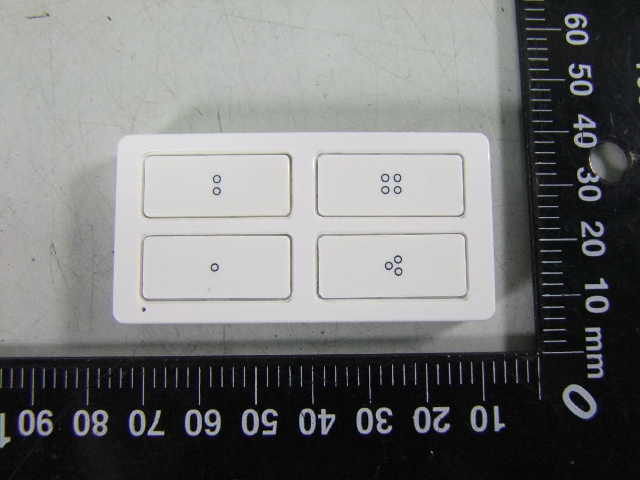
U2ZZW5314
Oct 28, 2020Z-Wave 700s 4-Button Simple Controller
Equipment Class
DXT - Part 15 Low Power Transceiver, Rx Verified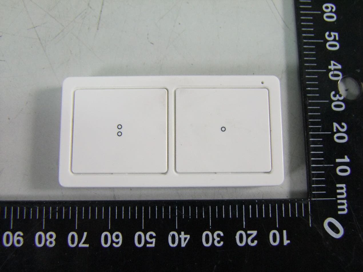
U2ZZW5313
Oct 28, 2020Z-Wave 700s 2-Button Simple Controller
Equipment Class
DXT - Part 15 Low Power Transceiver, Rx Verified
U2ZZW6309
Oct 27, 2020Z-Wave 700s Water Leak Sensor
Equipment Class
DXT - Part 15 Low Power Transceiver, Rx Verified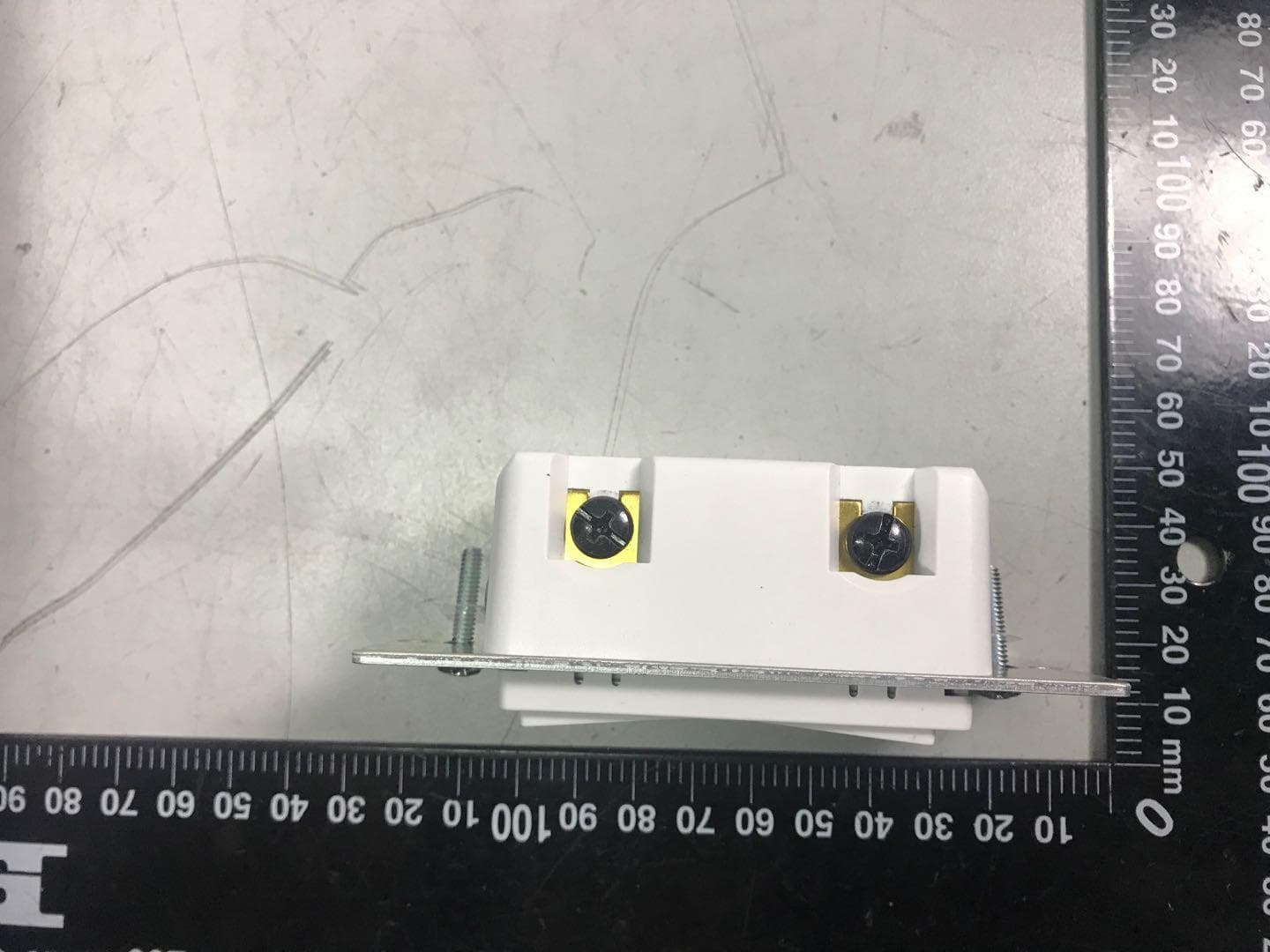
U2ZZW3012
Oct 13, 2020Z-Wave 700s In-Wall No Neutral Dimmer
Equipment Class
DXT - Part 15 Low Power Transceiver, Rx Verified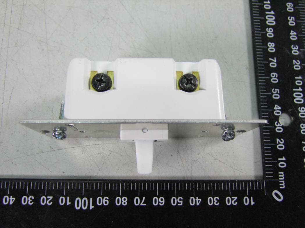
U2ZZW3011DV
Oct 12, 2020Z-Wave In-Wall Toggle Dimmer 0-10V 120/277V
Equipment Class
DXT - Part 15 Low Power Transceiver, Rx Verified