U2ZZW5303Remote controller
Sheenway Asia Ltd.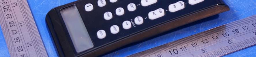
Click to zoom
Application Details
- Equipment Class
- DXX - Part 15 Low Power Communication Device Transmitter
- Date of Grant
- May 09, 2011
- Application Purpose
- Original Equipment
- Date of Application
- May 09, 2011
- Equipment Note
- Remote controller
- Frequency Range
- 908.40000000 - 908.40000000
- Company
- Sheenway Asia Ltd.
- Country
- China
Documents & Files
Document Text
Text extracted from the exhibit documents filed with the FCC. Open a document above to read the original.
Users Manual
45633 Instructions rev 1-a.doc Page 1 of 14 1/13/2010 INTRODUCTION Thank you for purchasing the GE 45633 Advanced Remote. This remote allows you to control Z-Wave certified door locks and thermostats as well as up to 18 individual Z-Wave lighting devices. You can also set up and control up to 18 groups of lights as well as 18 scenes for task or mood lighting. Groups can include up to 232 Z-Wave devices and each scene can include up to 32 Z-Wave devices. Lights can be included in multiple groups. Scenes can include lights from different groups. Your Z-Wave home control network can include up to 232 Z-Wave enabled devices. Additional features include: Easy to use LCD menu system Backlit keypad and LCD Event programming which allows you to set timed events such as turning on all of your lights at a certain time every day. Backlit display with easy to use menu Mode Buttons: Thermostat – Use to check and adjust system and temperature settings on a Z- Wave enabled thermostat LIGHT – Use to program and/or control individual lights GROUP - Use to program and/or turn multiple lights ON or OFF with one button SCENE – Use to program and/or control multiple lights at preset brightness levels. The same light may be included in multiple scenes. Menu Selection Buttons: Use arrow buttons to scroll between menu items Press OK to select the displayed menu item Setup / Shift Button Press and hold to enter setup mode. You can then add lights to, or delete them from your control network. You can also create or modify groups and scenes, etc. Press and release to SHIFT number buttons from 1 - 9 to 10 - 18. Number Buttons Use to control up to 18 individual lights, 18 groups and 18 scenes. Press & release to turn lights on/off. Press & hold to adjust brightness. Press the button for numbers 1 – 9; Press SHIFT, then the button for numbers 10-18 Cancel Button Press and release to cancel the current programming operation All Button Use to turn ON or OFF all Z-Wave lighting at the same time. Press ALL and then any number button Door Lock Button: Check lock status and activate locking mechanism 45633 Instructions rev 1-a.doc Page 2 of 14 1/13/2010 If this remote is used as the primary controller, you must use it to create your control network. You can use multiple remote controls with your Z-Wave lighting control network, however, only one remote will act as the primary controller. The primary controller must be used to add or delete devices (lights / nodes) from your network. All other controllers are considered secondary and can be used to create groups and/or scenes and control your lighting however secondary controllers cannot add or delete devices from your network. NOTE: This product can be operated in one Z-Wave network with Z-Wave certified devices from other manufacturers and/or other applications. The different listening nodes within the network can act as repeaters regardless of vendor. For best results, please read and perform all the remaining instructions before using the remote. Keep this guide for future reference. Z-WAVE TERMINOLOGY Primary Controller: This is the main device used to set up and control your Z-Wave network. There can only be one primary controller and it must be used to add or delete devices. A primary controller can be a portable device like a hand-held remote, a static controller (permanently installed & never moved), a Z- Wave enabled PC or a Z-Wave enabled Ethernet router/bridge. Secondary Controller: The Z-Wave network supports multiple controllers so the residents can use additional Z-Wave remotes throughout the home. If the secondary controller is the same brand and model as the primary, it will have all of the same capabilities as the primary with one exception; the secondary controller can not be used to add or delete devices. Slave: Devices within the Z-Wave network are either controllers or slaves. Most AC powered slaves also function as repeaters in the network, and when required, relay the command signals to the destination device. Battery powered devices like motion detectors are typically asleep and do not function as repeaters Home Control Network: Your controllers and every Z-Wave device you have added with the primary controller are linked together into a wireless network. Each device in your network has a unique address assigned to it and cannot be activated by your neighbor’s Z-Wave controller. Light/Node/Device: Node is the technical term used to describe a Z-Wave device in your home control network. Please note that the terms “Node”, “Device” and “Light” all refer to an individual Z-Wave enabled device and are interchangeable within the context of these instructions. Group: Multiple Z-Wave devices can be turned ON or OFF with a single command when they are placed into a Group. One example would be grouping your porch light, exterior garage lights and patio lights together so that they could all be turned ON if you hear a strange sound in the middle of the night. Scene: A scene lets you establish preset brightness levels for multiple Z-Wave controlled lights and then control them with one command. This is ideal for mood or task lighting. Scene 1 could be the family room lights set to dim for watching TV. Scene 2 could have the same lights set to a different brightness level for other activities like reading or entertaining. Event: An event is something you want to happen at a specific time and day. This could be everyday, a specific day of the week, Monday through Friday, Saturday & Sunday only, or a one time occurrence. Events can be set up to control an individual device, a group or a scene. Replication: This is the Z-Wave term for copying your lighting control network information to a new controller. 45633 Instructions rev 1-a.doc Page 3 of 14 1/13/2010 INSTALLING BATTERIES Three “AAA” Alkaline batteries (not included) are required. Battery Use and Safety Use only fresh batteries of the required size and recommended type. Do not mix old and new batter…
Text truncated - open the document above for the full version.
ID Label/Location Info
11MM 4.5MM 5.5mm 25mm Date code label location GE logo location Date : 30-Mar-2011
Operational Description
Description of a simple operation TO RESET YOUR NETWORK: 1. Press and hold SETUP until the screen displays LGHT SETUP 2. Use either Arrow key to scroll until the display reads NETWORK 3. Press OK and the screen will display RESET 4. Press OK and the screen will display RESETTING 5. When the screen displays SUCCESS, you have successfully reset network information. 6. Reset all individual devices as instructed in the section on deleting devices from the network. ADDING A DEVICE (NODE / LIGHT) TO THE NETWORK In order to control the lights, they must be Z‐Wave enabled and you must first add them to your home network. TO ADD A DEVICE TO YOUR HOME NETWORK AND ASSIGN IT TO A SPECIFIC NUMBER KEY: 1. Press and hold SETUP until screen displays LGHT SETUP 2. Press OK and the screen will display ADD 3. Press OK and the screen will display TO NETWORK 4. Use either Arrow key to scroll until the display reads TO A KEY and then press OK 5. Press a digit (1‐9) for the device location you wish to add. Press SETUP (SHIFT) and the digit (1‐ 9) if you are adding devices 10 through 18. 6. Press OK and the screen will display SETUP WAITING 7. Press the button on the device so that it communicates with the remote. 8. When the screen displays SUCCESS, you have successfully added the device to the number key and your network. CONTROLLING INDIVIDUAL LIGHTS (DEVICES / NODES) You can control a light to turn on or off, or change its brightness level. The operation of a specific device varies by product. Refer to the manual for that device to learn its specific operation. Turning a Light On or Off: To turn a light on, press and release the ON key for less than one second. The screen will display the selected LIGHT/NODE and ON. To turn a light off, press and release the OFF key for less than one second. The screen will display the selected LIGHT/NODE and OFF Setting a Light’s Brightness Level: To make a light brighter, press and hold the ON key for more than one s econd. The screen will display selected LIGHT/NODE and BRT. The light will continue to grow brighter until the key is released. To make a light dim, press and hold the OFF key for more than one second. The screen will display selected LIGHT/NODE and DIM. The light will continue to grow dimmer until the key is released. DELETING A DEVICE (LIGHT / NODE) FROM YOUR NETWORK This completely removes the device from your home control network and resets the device to its factory default settings. 1. Press and hold SETUP until screen displays LGHT SETUP 2. Press OK followed by pressing the cursor right key 2 times the screen will display DELETE 3. Press OK 4. Press the button on the device so that it communicates with the remote. 5. When the screen displays SUCCESS, you have successfully deleted the node/light from your network GROUPS You can create a collection of devices (lights / nodes) that you can control as a group. You can set up a maximum of 18 groups. A group can contain up to 232 devices. To create or add a device to a group: 1. Press and hold SETUP until screen displays LGHT SETUP 2. Use either Arrow key to scroll until the display reads GRP SETUP 3. Press the OK key and the screen will display ADD 4. Press OK and the screen will display SEL DIGIT 5. Press a digit (1‐9) for the group you wish to add the device to. Press SHIFT and the digit (1‐9) if you are adding a device to groups 10 through 18. 6. Press the OK key and the screen will display SETUP WAITING 7. Press the button on the device so that it communicates with the remote. 8. When the screen displays SUCCESS, you have successfully added the device to your group. To control a Group: 1. Press GROUP once to put the remote into “GROUP Control” mode. The screen will display GROUP. The remote will stay in this mode until the Light, Scene or All mode is activated. 2. Press the digit key for the group you wish to control (1‐9). Press SHIFT and the digit (1‐9) if you are controlling groups 10 through 18. The screen will display the selected Group. To turn a GROUP on, press and release the ON key for less than one second. The screen will display the selected GROUP and ON. To turn a GROUP OFF, press and release the OFF key for less than one second. The screen will display the selected GROUP and OFF Removing a Device (Light / Node) from a Group: This only removes the device from a specific group. The device is still part of your home control network and the group still exists (if there were more than one device in it to start). 1. Press and hold SETUP until the screen displays LGHT SETUP 2. Use either Arrow key to scroll until the display reads GRP SETUP 3. Press the OK key followed by the cursor right key once and the screen will display REMOVE 4. Press the OK key and the screen will display SEL DIGIT 5. Press a digit (1‐9) for the group you wish to remove the device from. Press SHIFT and the digit (1‐9) if you are removing a device from groups 10 through 18. 6. Press the OK key and the screen will display SETUP WAITING 7. Press the button on the device you wish to remove. 8. When the screen displays SUCCESS, you have successfully removed the device. Deleting a Group: This only deletes the specific group. All of the devices are still part of your home control network. 1. Press and hold SETUP until the screen displays LGHT SETUP. 2. Use either Arrow key to scroll until the display reads GRP SETUP 3. Press the OK key, followed by the cursor right key 2 times and the screen will display DELETE 4. The screen will display SEL DIGIT 5. Press a digit (1‐9) for the group you wish to delete. Press Shift and the digit (1‐9) if you are deleting groups 10 through 18. 6. Press the OK and the screen will display SUCCESS. Operating Frequency: 908.4MHz Antenna: Integral antenna
Test Report
FCC TEST REPORT For LCD Remote Control Model Number: ZW5303 FCC ID: U2ZZW5303 Report Number : WT118001110 Test Laboratory : Shenzhen Academy of Metrology and Quality Inspection National Testing Center for Digital Electronic Products Site Location : Bldg. Metrology and Quality Inspection, Longzhu Road, Shenzhen, Guangdong, China Tel : 0086-755-26941599 Fax : 0086-755-26941545 Web : www.smq.com.cn Report No.: WT118001110 Page 2/16 Test report declaration Applicant : SHEENWAY ASIA LTD. Address : Room 1313, 13/F., Austin Tower, Tsim Sha Tsui, Kowloon, Hong Kong. Manufacturer : KONIG ELECTRONIC (HUIZHOU) LTD. Address : 2-Plant, East Lake Side, QingTang, Lian He Village, Shui Kou, Hui Cheng District, Huizhou, GuangDong, China. Factory : KONIG ELECTRONIC (HUIZHOU) LTD. Address : 2-Plant, East Lake Side, QingTang, Lian He Village, Shui Kou, Hui Cheng District, Huizhou, GuangDong, China. EUT Description : LCD Remote Control Model No : ZW5303 FCC ID : U2ZZW5303 Test Standards: FCC Part 15 15.249 The EUT described above is tested by Shenzhen Academy of Metrology and Quality Inspection EMC Laboratory to determine the maximum emissions from the EUT. Shenzhen Academy of Metrology and Quality Inspection EMC Laboratory is assumed full responsibility for the accuracy of the test results. The test data, data evaluation, test procedures, and equipment configurations shown in this report were made in accordance with the procedures given in ANSI C63.4 (2003) and the energy emitted by the sample EUT tested as described in this report is in compliance with FCC Rules Part 15.249. The test report is valid for above tested sample only and shall not be reproduced in part without written approval of the laboratory. Project Engineer: Date: Apr.28,2011 (Ryan Chen) Checked by: Date: Apr.28,2011 (Dewelly Yang) Approved by: Date: Apr.28,2011 (Peter Lin) Report No.: WT118001110 Page 3/16 TABLE OF CONTENTS TEST REPORT DECLARATION........................................................................................................2 1. TEST RESULTS SUMMARY...................................................................................................4 2. GENERAL INFORMATION......................................................................................................5 2.1. Report information..........................................................................................................5 2.2. Laboratory Accreditation and Relationship to Customer.........................................5 2.3. Measurement Uncertainty.............................................................................................5 3. PRODUCT DESCRIPTION.......................................................................................................6 3.1. EUT Description..............................................................................................................6 3.2. Related Submittal(s) / Grant (s)...................................................................................6 3.3. Block Diagram of EUT Configuration..........................................................................6 3.4. Operating Condition of EUT..........................................................................................6 3.5. Special Accessories.......................................................................................................7 3.6. Equipment Modifications...............................................................................................7 3.7. Support Equipment List.................................................................................................7 3.8. Test Conditions...............................................................................................................7 4. TEST EQUIPMENT USED........................................................................................................8 5. CONDUCTED DISTURBANCE TEST....................................................................................9 5.1. Test Standard and Limit................................................................................................9 5.2. Test Procedure...............................................................................................................9 5.3. Test Arrangement...........................................................................................................9 5.4. Test Data.........................................................................................................................9 6. RADIATED DISTURBANCE TEST.......................................................................................10 6.1. Test Standard and Limit..............................................................................................10 6.2. Test Procedure.............................................................................................................10 6.3. Test Arrangement.........................................................................................................10 6.4. Test Data.......................................................................................................................11 7. OCCUPIED BANDWIDTH......................................................................................................13 7.1. Test Standard and Limit..............................................................................................13 7.2. Test Procedure.............................................................................................................13 7.3. Test Arrangement.........................................................................................................13 7.4. Test Data.......................................................................................................................13 8. BAND EDGE.............................................................................................................................14 8.1. Test Standard and Limit.......…
Text truncated - open the document above for the full version.
Test Setup Photos
Radiated disurbance
Contact Information
Applicant
Sammel Tung
Test Firm
Shenzhen Academy of Metrology & Quality InspectionPeter Lin
Technical Specifications
| # | Rule Parts | Frequency Range | Power Output |
|---|---|---|---|
| 1 | 15C | 908.4 MHz - 908.4 MHz | - |
Other Applications from Sheenway Asia Ltd.
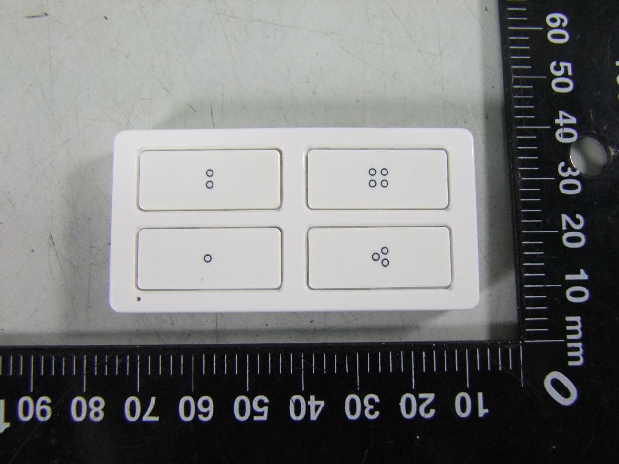
U2ZZW5314
Oct 28, 2020Z-Wave 700s 4-Button Simple Controller
Equipment Class
DXT - Part 15 Low Power Transceiver, Rx Verified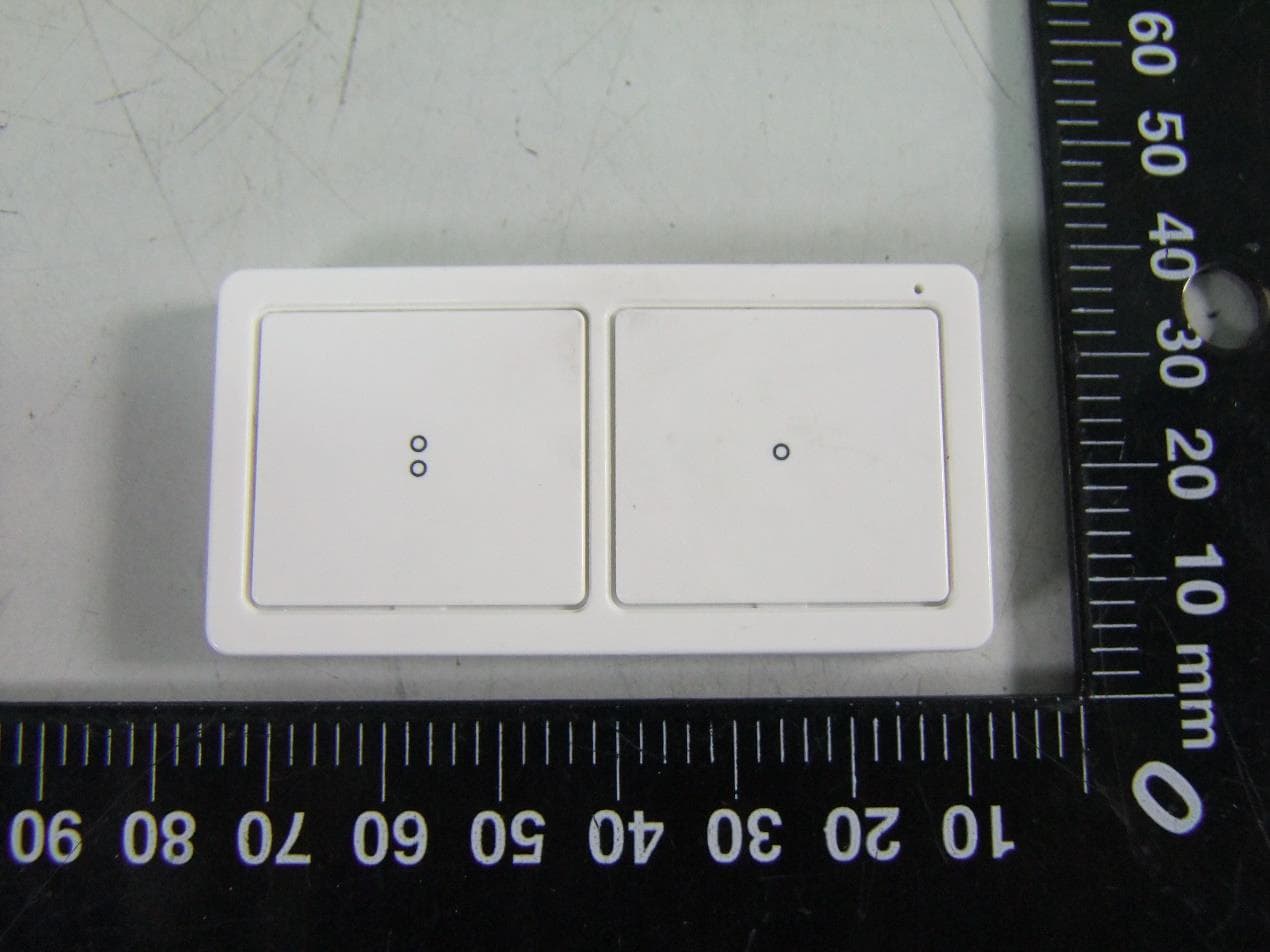
U2ZZW5313
Oct 28, 2020Z-Wave 700s 2-Button Simple Controller
Equipment Class
DXT - Part 15 Low Power Transceiver, Rx Verified
U2ZZW6309
Oct 27, 2020Z-Wave 700s Water Leak Sensor
Equipment Class
DXT - Part 15 Low Power Transceiver, Rx Verified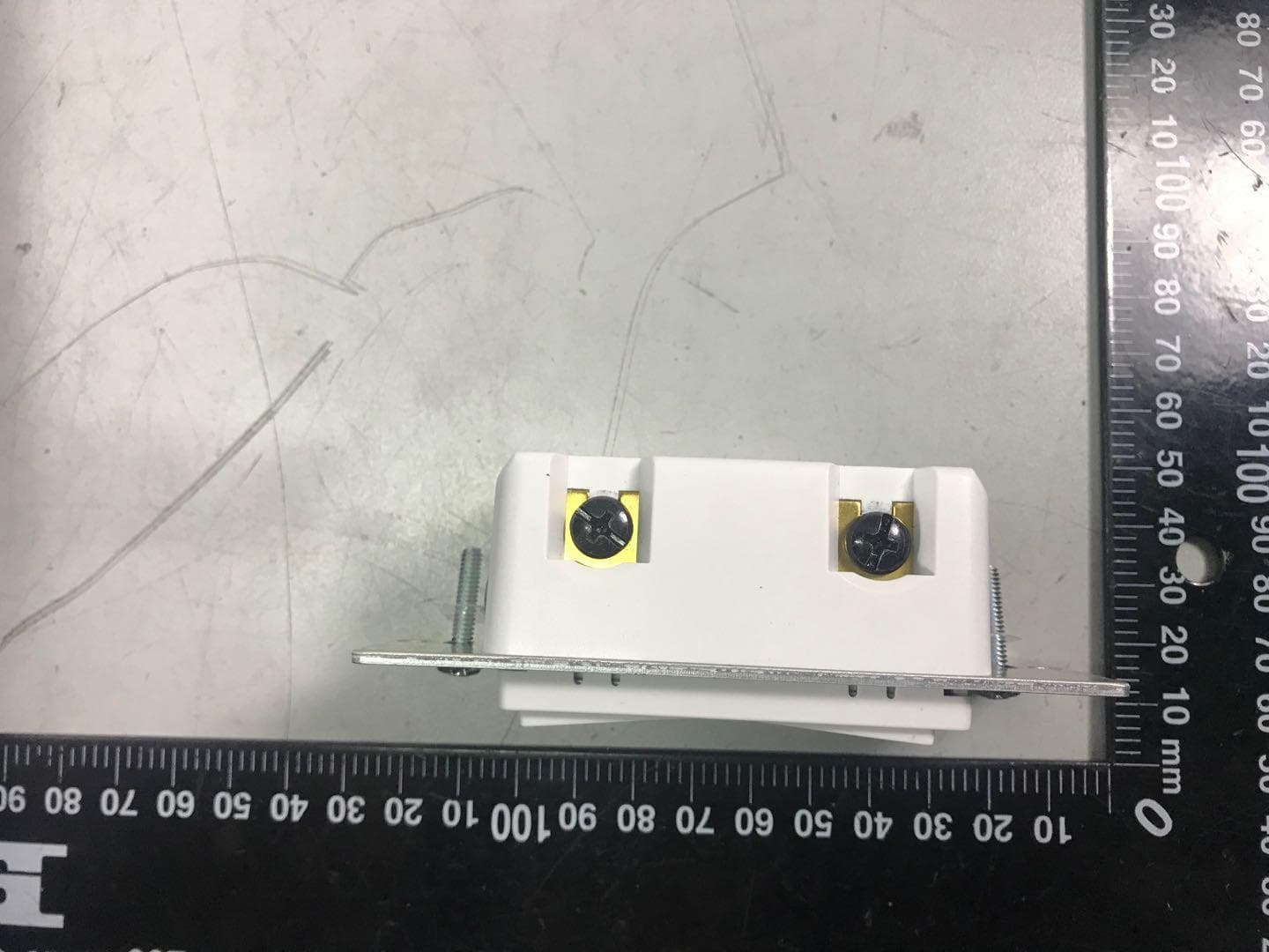
U2ZZW3012
Oct 13, 2020Z-Wave 700s In-Wall No Neutral Dimmer
Equipment Class
DXT - Part 15 Low Power Transceiver, Rx Verified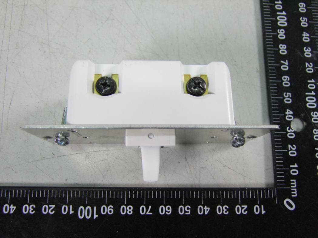
U2ZZW3011DV
Oct 12, 2020Z-Wave In-Wall Toggle Dimmer 0-10V 120/277V
Equipment Class
DXT - Part 15 Low Power Transceiver, Rx Verified