U4L01080410PressureWire� Aeris
St Jude MedicalApplication Details
- Equipment Class
- DXX - Part 15 Low Power Communication Device Transmitter
- Date of Grant
- Mar 03, 2008
- Application Purpose
- Original Equipment
- Date of Application
- Mar 02, 2008
- Equipment Note
- PressureWire� Aeris
- Frequency Range
- 2402.00000000 - 2480.00000000
- Company
- St Jude Medical
- Country
- United States
Documents & Files
Document Text
Text extracted from the exhibit documents filed with the FCC. Open a document above to read the original.
Users Manual
1(17) Instruction for Use PressureWire® Aeris, 20828 Rev 0F; will be released as Rev 01 (Generated from approved Master Labeling Specification PW Aeris Rev 07F) Table of Contents CONTENTS DESCRIPTION 1. INDICATION FOR USE 2. CONTRAINDICATIONS 3. GENERAL WARNINGS 4. GENERAL PRECAUTIONS 5. ADVERSE EVENTS 6. PREPARATIONS FOR USE 7. DIRECTIONS FOR USE, CORONARY MEASUREMENTS 8. DIRECTIONS FOR USE, INTERVENTIONAL PROCEDURE 9. DIRECTIONS FOR USE, INTRACARDIAC MEASUREMENTS PRESSURE PERFORMANCE SPECIFICATION RADIO SIGNAL SPECIFICATION FCC STATEMENT TRANSPORT STORAGE TRANSMITTER LIGHT INDICATORS COMPLIANCE WITH REGULATORY REQUIREMENTS RoHS DECLARATION (for Chinese IFU only) PATENTS WARRANTY AND LIMITATIONS SYMBOLS WITH EXPLANATIONS CONTENTS - 0.014” (0.36 mm) guidewire - Disconnectable transmitter – to be used with the guidewire it is delivered with - Torque device DESCRIPTION (See Diagram 1) - PressureWire ® 0.014” (0.36 mm) is a guidewire with a high fidelity sensor located just proximal to the 3 cm radiopaque shapeable tip. - PressureWire ® has a nominal diameter of 0.014” (0.36 mm). - Refer to product label for guidewire length. - The signals from the sensor can be used for measurements of cardiac and intravascular blood pressure and estimations of Fractional Flow Reserve (FFR). 2(17) Diagram 1: PressureWire ® 1. INDICATION FOR USE PressureWire ® is indicated to direct a catheter through a blood vessel and to measure physiological parameters in the heart and in the coronary and peripheral blood vessels. 2. CONTRAINDICATIONS PressureWire ® is contraindicated for use in the cerebral vasculature. 3. GENERAL WARNINGS - PressureWire ® is intended for single use only. - Do not resterilize or reuse: the contents may be damaged or distorted. - Prior to use and when possible during the procedure, inspect PressureWire ® carefully for bends, kinks or other damage. Do not readjust any bend or kink. - PressureWire ® must not be used if it has been damaged in any way; otherwise, vessel/ventricle damage and/or inaccurate pressure signals or inaccurate torque response may occur. - When introducing PressureWire® in a diagnostic case, flush the catheter and administer anticoagulation as for a standard catheterization procedure or clotting may occur. - Do not torque PressureWire ® without observing corresponding movement of the tip; otherwise vessel/ventricle trauma may occur. 3(17) - Always advance or withdraw PressureWire ® slowly. Never push, withdraw or torque PressureWire ® if it meets resistance. 4. GENERAL PRECAUTIONS - Federal (USA) law restricts this device to sale by or on the order of a physician. - PressureWire ® is only intended to be used with PressureWire ® Receiver. - PressureWire ® shall not be used with any other transmitter than the one which it is delivered with, or unreliable readings will be registered. - Refer to instructions supplied with any interventional devices to be used in conjunction with PressureWire ® for their intended uses, contraindications and potential complications. - Do not use PressureWire ® with atherectomy catheters. These systems may cause PressureWire ® to fold back upon itself and become lodged in the atherectomy catheter. If this occurs, withdraw both the atherectomy catheter and PressureWire ® simultaneously. - PressureWire ® does not give sufficient support for guiding catheter exchange. - Do not use with interventional devices with a too short guidewire rail length as PressureWire ® may fold or fracture during manipulation. - Confirm the compatibility of PressureWire ® diameter with the interventional device before actual use. - Free movement of the guidewire within the interventional device is an important feature of a steerable guidewire system because it gives the user valuable tactile information. Test the system for any resistance prior to use. - Adjust or replace the hemostatic valve with an adjustable valve if it is found to inhibit guidewire movement. - When PressureWire® is disconnected from the transmitter during the procedure make sure the male connector does not come into contact with conductive surfaces thus avoiding unintentional connection with other equipment. - False pressure readings may occur if the male connector is: - not dry, clean and free of coagulated blood. - not fully inserted into the bottom of the transmitter (indicated by yellow light). - bent or damaged. 4(17) - The PressureWire® Transmitter housing is protected against the effects of a discharge of a cardiac defibrillator. PressureWire ® readings may however be affected by defibrillation. Attempt recalibration of PressureWire ® after defibrillation according to “Recalibration” in the section Preparation for use. - Avoid abrasion of PressureWire ® coating. To avoid guidewire damage and possible shearing of the polymer coating, do not withdraw or manipulate PressureWire ® in a metal cannula or sharp-edged object. - If PressureWire ® is taken out during the procedure in order to be reintroduced into the patient make sure the PressureWire ® distal part is kept wet in the meantime. Make sure that the transmitter is kept dry. - For optimal pressure measurement adjust the position of PressureWire ® so that the sensor does not touch the atrial or ventricular walls, to avoid measurement artefacts due to movement. - After use, the product may be a potential biohazard. Handle and dispose of PressureWire ® in accordance with medical practice and applicable local, state and federal laws and regulations. NOTE: The transmitter contains silver oxide button type batteries with in total < 2% mercury, allowed to be put on the market according to the battery directive 2006/66/EG.The signal performance requires the batteries to be permanently affixed and the transmitter to be sealed, which, according to article 11 in the same directive, exclude the batteries from the requirement to be possible to remove. Dispose as ordinary potentially biohazardous material. 5. ADVERSE EVENTS Potential complications wh…
Text truncated - open the document above for the full version.
External Photos
External photo of the product. PressureWire® Transmitter, Part no. 20824 About normal size:
ID Label/Location Info
1(2) FCC ID marking for the transmitter in PressureWire® Aeris. (Rev 02) Background: PressureWire® Aeris is a guidewire for pressure measurement of intravascular pressure in the heart and, coronary and peripheral blood vessels. The transmitter which is part of the PressureWire® Aeris is outside the body. PressureWire® Aeris including transmitter is sterile and for single use only. The transmitter transfers measured pressure signal in the 2.4 GHz frequency band to the PressureWire® Receiver, which is connected to a cathlab hemodynamic recording system. About normal size of the transmitter: Marking at the housing end. Marking: PressureWire® Aeris is delivered in a Tyvek pouch which is marked with a label including the FCC ID, see Attachment I, Label PressureWire® Aeris. The FCC ID: U4L01080410 is visible at the housing end of the transmitter. The text is very small but visible see next page for an enlarged picture. Moreover the FCC ID is mentioned in the Instructions for Use (IFU) for the product. Normal handling: PressureWire® Aeris is unpacked from the packaging- a Tyvek pouch, used during the examination and treatment of the patient for a couple of hours and then disposed. The PressureWire® Aeris including transmitter is contaminated after use. 2(2)
Test Report
Test report no 704810-2 Page 2(21) CONTENTS Page 1. Client information.............................................................................................................................3 2. Equipment under test (EUT)...........................................................................................................3 2.1 Identification of the EUT according to the manufacturer/client declaration...................3 3. Test specifications...........................................................................................................................4 3.1 Standards................................................................................................................................4 3.2 Additions, deviations and exclusions from standards.......................................................4 3.3 Test set-up..............................................................................................................................4 3.4 Test conditions.......................................................................................................................4 4.Test summary....................................................................................................................................5 5.Radiated spurious emissions..........................................................................................................6 5.1 Measurement set-up..............................................................................................................6 5.2 Test protocol...........................................................................................................................8 6.Radiated output power...................................................................................................................16 6.1 Test protocol.........................................................................................................................16 6.2 Limit........................................................................................................................................16 7. Band edge compliance..................................................................................................................17 7.1 Test protocol.........................................................................................................................17 8 Instrumentation list..........................................................................................................................19 Appendix I – Uncertainties summary...............................................................................................20 Appendix II – Photo of the EUT........................................................................................................21 Intertek Semko AB Torshamnsgatan 43, Box 1103, SE-164 22 Kista, Sweden Telephone +46 8 750 00 00, Fax +46 8 750 60 30, www.sweden.intertek-etlsemko.com Registered in Sweden: No SE556024059901, Registered office: As address r d f n c Test report no 704810-2 Page 3(21) 1. CLIENT INFORMATION The EUT has been tested by request of Company: Radi Medical Systems AB Palmbladsgatan 10 754 50 Uppsala Sweden Name of contact: Björn Palmgren 2. EQUIPMENT UNDER TEST (EUT) 2.1 Identification of the EUT according to the manufacturer/client declaration Equipment: Wireless PressureWire® system Type / Model: 12056 Brand name: PressureWire® Aeris Manufacturer: Radi Medical Systems AB Rating/Supplying voltage: 3,0 V DC, Class III Antenna gain: 1,2 dBi External antenna connector: No Frequency range: 2400 - 2483,5 MHz Number of channels: 79 Modulation characteristics: FHSS Stand by mode supported: No Low channel 2402 MHz Mid channel 2441 MHz High channel 2480 MHz Duty cycle 7% Intertek Semko AB Torshamnsgatan 43, Box 1103, SE-164 22 Kista, Sweden Telephone +46 8 750 00 00, Fax +46 8 750 60 30, www.sweden.intertek-etlsemko.com Registered in Sweden: No SE556024059901, Registered office: As address r d f n c Test report no 704810-2 Page 4(21) 3. TEST SPECIFICATIONS 3.1 Standards FCC 47 CFR part 15 (2006) Subpart B – Unintentional radiators, class B FCC 47 CFR part 15 (2006) Subpart C – Intentional radiators Measurements methods according to ANSI C63.4-2003 3.2 Additions, deviations and exclusions from standards No additions, deviations or exclusions have been made from standard. 3.3 Test set-up Measurement set-up for all tests is described in the radiated spurious emissions section. 3.4 Test conditions If not additionally specified, the tests were performed under the following environmental conditions: Parameter Normal Supplying voltage, V 3,0 V DC Air temperature, o C 20-24°C Intertek Semko AB Torshamnsgatan 43, Box 1103, SE-164 22 Kista, Sweden Telephone +46 8 750 00 00, Fax +46 8 750 60 30, www.sweden.intertek-etlsemko.com Registered in Sweden: No SE556024059901, Registered office: As address r d f n c Test report no 704810-2 Page 5(21) 4. TEST SUMMARY The results in this report apply only to the sample tested. Test FCC Reference Result Radiated output power 15.249 Pass Band Edge Compliance 15.249 Pass Out of band spurious emission, radiated 15.249 Pass* NT = Not Tested NA = Not Applicable *The measured result is below the limit by a margin less than the measurement uncertainty; it is therefore not possible to state compliance based on the 95 % level of confidence. However, the result indicates that compliance is more probable than non-compliance with the specification limit. Intertek Semko AB Torshamnsgatan 43, Box 1103, SE-164 22 Kista, Sweden Telephone +46 8 750 00 00, Fax +46 8 750 60 30, www.sweden.intertek-etlsemko.com Registered in Sweden: No SE556024059901, Registered office: As address r d f n c Test report no 704810-2 Page 6(21) 5. RADIATED SPURIOUS EMISSIONS 5.1 Measurement set-up Test site: Small anechoic shielded chamber (30 – 1000 MHz) In the Small anechoic shielded chamber the EUT was placed on a non-metallic table, 1,5 m above the floor. The …
Text truncated - open the document above for the full version.
Test Setup Photos
TEST SET-UP PHOTOS MODEL: PressureWire ® Aeris Radiated spurious emission 30-1000 MHz Radiated spurious emission 1-26 GHz
Contact Information
Applicant
Erdie De Peralta(Regulatory Affairs, Director)
Technical Contact
Radi Medical Systems ABMagnus Samuelsson
[email protected]+46-18-161000
Palmbladsgatan 10 · Uppsala · Sweden
Non-Technical Contact
Radi Medical Systems ABBj�rn Palmgren
[email protected]+46(0)18161000
Test Firm
Intertek SEMKO ABNiklas Bostrom
Technical Specifications
| # | Rule Parts | Frequency Range | Power Output |
|---|---|---|---|
| 1 | 15C | 2.40 GHz - 2.48 GHz | - |
Other Applications from St Jude Medical
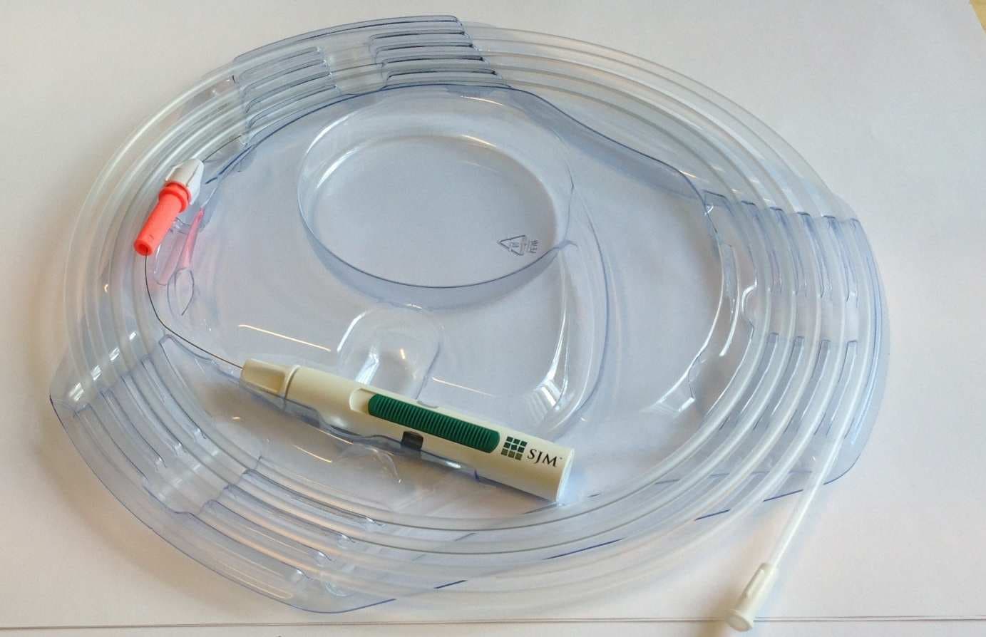
U4L2
Dec 19, 2013PressureWireTM AerisTM
Equipment Class
DXX - Part 15 Low Power Communication Device Transmitter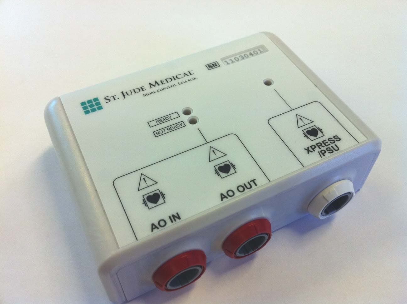
U4L201106
Sep 14, 2011Wi-Box
Equipment Class
DXX - Part 15 Low Power Communication Device Transmitter