U4L201106Wi-Box
St Jude Medical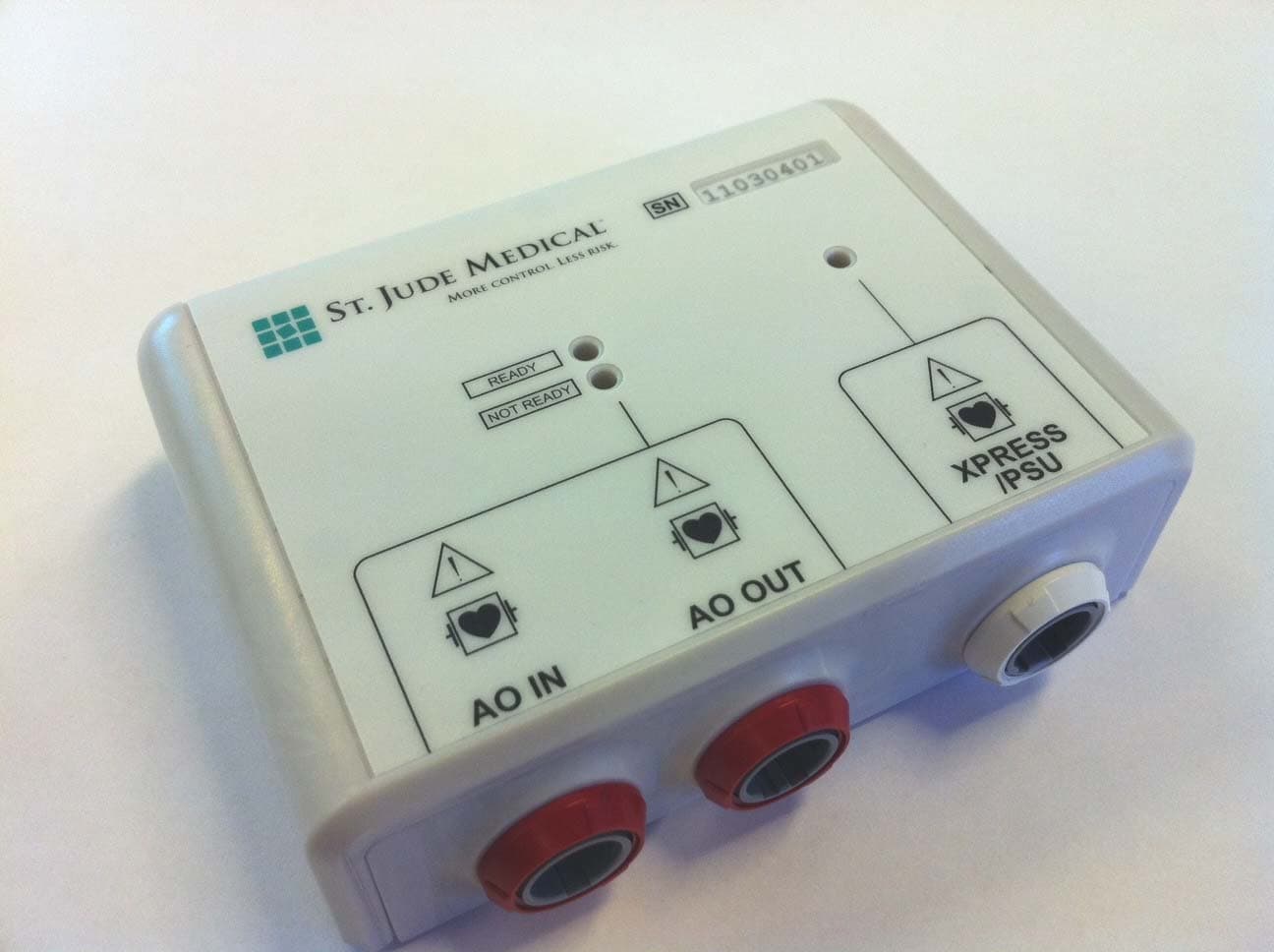
Click to zoom
Application Details
- Equipment Class
- DXX - Part 15 Low Power Communication Device Transmitter
- Date of Grant
- Sep 14, 2011
- Application Purpose
- Original Equipment
- Date of Application
- Sep 14, 2011
- Equipment Note
- Wi-Box
- Frequency Range
- 2400.00000000 - 2483.50000000
- Company
- St Jude Medical
- Country
- United States
Documents & Files
Document Text
Text extracted from the exhibit documents filed with the FCC. Open a document above to read the original.
Users Manual
Wi-Box ™ ENGLISH4 ENGLISH 1. PRODUCT NAME Wi-Box ™ 2. CONTENT Wi-Box Wi-Box Xpress Cable (Ordered separately.) Wi-Box External Power Supply (Ordered separately.) Wi-Box Excitation plug (Ordered separately.) 3. DESCRIPTION Wi-Box is used for measurement of pressure from an external connected pressure transducer. It has an eavesdropping function such that a hemodynamic recording system can be directly connected to the pressure transducer at the same time as Wi-Box measures the pressure and transmits it on a specific radio interface. An isolated interface provides the measured pressure as an analog output signal. 4. INDICATION FOR USE Wi-Box is indicated to condition and transmit a physiological signal via radiofrequency. 5. GENERAL WARNINGS Wireless transmitter and RadiAnalyzer ™ Xpress pressure output ports are not designed nor intended for vital signs monitoring. Modification of this equipment is not allowed. 4 6. GENERAL PRECAUTIONS Federal (USA) law restricts distribution and sales of Wi-Box to sale by or on the order of a physician. Handle Wi-Box in accordance with medical practice and applicable local, state and federal laws and regulations. Do not use Wi-Box if it has been subject to damage. If Wi-Box has been subject to accidental wetting, wipe off and perform leakage current measurement and functional test. Software upgrade shall not be performed during a clinical procedure. 7. INSTALLATION 7.1 Normal Operation NOTE:Wi-Box needs to be installed in a place that ensures adequate radio transmission with receiving unit. Radio range is reduced by objects and walls, keep Wi-Box and receiving unit in line of sight wherever possible. NOTE:High frequency surgical equipment shall not be used in the close proximity of the device since this could influence the performance of the device. a. Mount Wi-Box vertically on or close to the cathlab table using the enclosed mounting details. The cable connectors shall be facing downward to minimize stress on cabling and connectors and to protect the unit from ingression of fluids. NOTE:After mounting, Wi-Box is securely fastened and may be very difficult to remove. If Wi-Box needs to be repositioned, be careful not to damage Wi-Box by bending. CAUTION:The used pressure transducer must have excitation impedance larger than 270Ω. CAUTION:All equipment connected to AO OUT must be CF classified and defibrillation proof. Failure to comply to these requirements will void the CF classification and defibrillation protection on AO IN. CAUTION:The person performing the connections of Wi-Box is responsible for forming a medical electrical system and the total system and patient leakage currents thereof. 5 NOTE:The test below shall be performed when changing type of blood pressure transducer. b. Connect the AO OUT connector on Wi-Box to a blood pressure channel on the ANSI/AAMI-BP22 compatible hemodynamic recording system using the corresponding St. Jude Medical monitor cable. c. Connect the blood pressure transducer to the AO IN using the corresponding St. Jude Medical adapter cable. For appropriate handling of the external pressure transducer (calibration, removing possible entrapped air, sterility, time limit before use, warm-up time or volume displacement) refer to its operating instructions. NOTE:Transducers marked for single-use may not be reused. d. Make sure that the blood pressure channel is powered. e. To verify correct pressure, apply a known pressure on the blood pressure transducer using a blood pressure simulator. If the green READY light is lit and the AO pressure is correctly displayed on the hemodynamic recording system, Wi-Box is ready to use. If the red NOT READY light is lit or the AO pressure is incorrectly displayed on the hemodynamic recording system, Wi-Box External Power supply needs to be connected to provide adequate power to the unit (see Wi-Box External Power Supply below). If the red NOT READY light is blinking, internal fail has occurred. Contact your St. Jude Medical representative. 7.2 Wi-Box External Power Supply (for low power hemodynamic recording systems) CAUTION:The only approved power supply to connect is C12785/ FW7333SM. CAUTION:The power supply shall be mounted at a location where it is protected from fluids. CAUTION:Mains power is disconnected by removing Wi-Box External Power Supply from the wall socket. Place Wi-Box External Power Supply such that it easily can be removed from the wall socket. a. Connect Wi-Box External Power Supply cable to the PSU connector on Wi-Box. b. Connect Wi-Box External Power Supply to a free wall socket using the appropriate wall socket adapter. The white light on Wi-Box shall now be lit indicating that Wi-Box is powered. c. To verify correct pressure, apply a known pressure on the blood pressure transducer using a blood pressure simulator. If the green READY light is lit and the AO pressure is correctly displayed on the hemodynamic recording system, Wi-Box is ready to use. If the red NOT READY light still is lit, an internal error has occurred. Try to reconnect Wi-Box External Power Supply. If the problem remains contact your St. Jude Medical representative. If the AO pressure is incorrectly displayed on the hemodynamic recording system, do not use the Wi-Box. Contact St. Jude Medical representative. d. If Wi-Box is intended to be used stand-alone without hemodynamic recording system, Wi-Box Excitation Plug shall be inserted in the AO OUT connector. 6 7.3 Use with RadiAnalyzer Xpress NOTE:Using Wi-Box in combination with RadiAnalyzer Xpress affects the performance of AO measurements in RadiAnalyzer Xpress, see 13 Technical specifications, Performance below. NOTE:Wi-Box cannot be used together with RadiAnalyzer Xpress if connected to a low power hemodynamic recording system and a Wi-Box External power supply is needed. a. Connect Xpress connector on Wi-Box to the AO IN connector on RadiAnalyzer Xpress using Wi-Box Xpress cable. b. Open the transducer to air and Zero AO on the RadiAnalyzer Xpr…
Text truncated - open the document above for the full version.
External Photos
1(1) External Photos St. Jude Wi-Box
ID Label/Location Info
1(1) Marking label and location St. Jude Wi-Box
Internal Photos
1(2) Internal Photos St. Jude Wi-Box 2(2)
Test Report
Test report no.1110792-3 Page2 (24 ) CONTENTS Page 11. CLIENT INFORMATION.....................................................................................................3 22. EQUIPMENT UNDERTEST (EUT)....................................................................................3 2.12.1IDENTIFICATION OF THEEUTACCORDING TO THE MANUFACTURER/CLIENT DECLARATION.. 3 2.22.2ADDITIONAL HARDWARE INFORMATION ABOUT THEEUT..................................................3 3TEST SPECIFICATIONS.........................................................................................................4 3.1STANDARDS........................................................................................................................4 3.2ADDITIONS,DEVIATIONS AND EXCLUSIONS FROM STANDARDS................................................4 3.3TEST FACILITY.....................................................................................................................4 3.4TEST SET-UP.......................................................................................................................4 3.5TEST CONDITIONS...............................................................................................................4 4TEST SUMMARY....................................................................................................................5 5RADIATED OUTPUT POWER ................................................................................................6 5.1TEST PROTOCOL.................................................................................................................6 5.2LIMIT.................................................................................................................................. 6 6SPURIOUS EMISSIONS (RADIATED)...................................................................................7 6.1MEASUREMENT UNCERTAINTY..............................................................................................7 6.2TEST EQUIPMENT................................................................................................................7 6.3MEASUREMENT SET-UP.......................................................................................................8 6.4TEST GRAPHS, TXMODE................................................................................................... 10 6.5TEST PROTOCOL, TXMODE...............................................................................................18 7OCCUPIED BANDWIDTH.....................................................................................................20 7.1TEST EQUIPMENT..............................................................................................................20 7.2TEST PROTOCOL...............................................................................................................20 8CONDUCTED EMISSION,AC PORT...................................................................................22 8.1TEST EQUIPMENT..............................................................................................................22 MEASUREMENT UNCERTAINTY......................................................................................................22 8.2TEST SET-UP.....................................................................................................................22 8.3TEST PROTOCOL...............................................................................................................23 PHOTO OF THE EUT...................................................................................................................24 Test report no.1110792-3 Page3 (24 ) 11.CLIENT INFORMATION The EUT has been tested by request of Company:St Jude Medical Systems AB Box 6350 751 35 Uppsala Sweden Name of contact:Mattias Dahlberg 22.EQUIPMENT UNDER TEST(EUT) 2.12.1 Identification of the EUT according to the manufacturer/client declaration Equipment:AO Interface Unit Type / Model:N/A Brand name:N/A Serial number:Unmarked Manufacturer:St Jude Medical Systems AB Rating/Supplying voltage:4 – 8 V DC Antenna gain:1,8 dBi External antenna connector:No Operating temperature range:10 to 40 °C Frequency range:2400- 2483,5 MHz Number of channels:79 Modulation characteristics:FHSS Stand by mode supported:No Low channel2402 MHz Mid channel2441 MHz High channel2480 MHz 2.22.2 Additional hardware information about the EUT The EUT consists of the following units: UnitTypeSerial number AO Interface UnitN/AUnmarked AC/DC AdapterFRIWO, 15.2765Unmarked Test report no.1110792-3 Page4 (24 ) 3TEST SPECIFICATIONS 3.1Standards FCC 47 CFR part 15 (2010) Subpart B– Unintentional radiators FCC 47 CFR part 15 (2010) Subpart C– Intentional Radiators; §15.249 Operation within the bands 902-928 MHz, 2400– 2483.5 MHz, 5725– 5850 MHz and 24.0– 24.25 GHz RSS-Gen, Issue 3 (December 2010): General Requirements and Information for the Certification of Radiocommunication Equipment RSS-210, Issue 8 (December 2010): Low Power Licence-Exempt Radio communication Devices (All Frequency Bands): Category I Equipment. Measurements methods according to ANSI C63.4-2009- Methods of Measurements of Radio-Noise Emissions from Low-Voltage Electrical and ElectronicEquipment in the Range of 9 kHz to 40 GHz and ANSI C63.10 -2009- StandardforTesting Unlicensed Wireless Devices 3.2Additions, deviations and exclusions from standards Nodeviations or exclusions have been made from standards. 3.3Testfacility Measurements were performed at Intertek Semko AB, located in Stockholm, Sweden 3.4Test set-up The EUT was connected toa measuring instrumentby cable if not otherwise specified in the report. 3.5Test conditions If not additionally specified, the tests were performed under the following environmental conditions: ParameterNormal Supplying voltage, V120 V AC (AC/DC adapter) Air temperature, o C20 -25 Test report no.1110792-3 Page5 (24 ) 4TEST SUMMARY The results in this report apply only to the …
Text truncated - open the document above for the full version.
Test Setup Photos
1(2) AIU - TEST SET-UP PHOTOS Radiated spurious emission 30-1000 MHz Radiated spurious emission 1000-26000 MHz 2(2) Conducted emission
Contact Information
Applicant
Erdie De Peralta(Regulatory Affairs, Director)
Technical Contact
Test Firm
Intertek Semko ABPar Iggstrom
[email protected]+46708750026
Technical Specifications
| # | Rule Parts | Frequency Range | Power Output |
|---|---|---|---|
| 1 | 15C | 2.40 GHz - 2.48 GHz | - |
Other Applications from St Jude Medical
U4L2
Dec 19, 2013PressureWireTM AerisTM
Equipment Class
DXX - Part 15 Low Power Communication Device TransmitterU4L01080410
Mar 03, 2008PressureWire� Aeris
Equipment Class
DXX - Part 15 Low Power Communication Device Transmitter