U4L2PressureWireTM AerisTM
St Jude Medical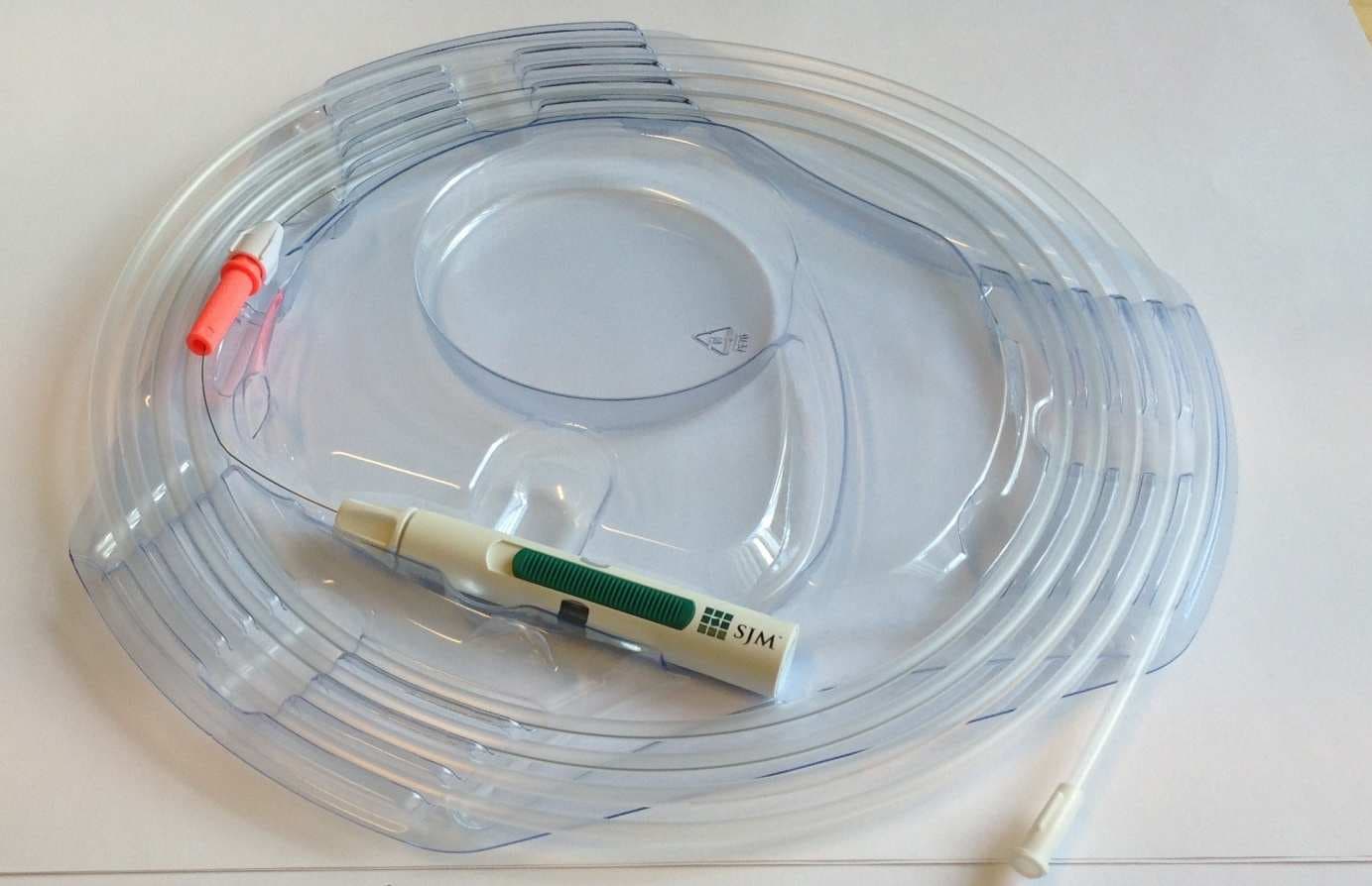
Click to zoom
Application Details
- Equipment Class
- DXX - Part 15 Low Power Communication Device Transmitter
- Date of Grant
- Dec 19, 2013
- Application Purpose
- Original Equipment
- Date of Application
- Dec 19, 2013
- Equipment Note
- PressureWireTM AerisTM
- Frequency Range
- 2402.00000000 - 2480.00000000
- Company
- St Jude Medical
- Country
- United States
Documents & Files
Document Text
Text extracted from the exhibit documents filed with the FCC. Open a document above to read the original.
Users Manual
PressureWire ™ Aeris ™ Guidewire Mounted Sensor en: Instructionsfor usees: Instruccionesde uso fr : Moded'emploipt: Instruçõesde utilização it: Istruzioniper l'usohr: Uputeza upotrebu de: Bedienungsanleitungsl: Navodilaza uporabo nl: Gebruiksaanwijzingua: Інструкція з експлуатації no: Bruksanvisning da: Brugsvejledning et: Kasutusjuhend fi: Käyttöohjeet sv: Bruksanvisning 51395139A-4 en: Instructionsfor use . . . . . . . . . . . . . . . . . . . . . . . . . . . . . . . . . . . . . . . . . . . . . . . . . . . . . . . . . . . 5 fr : Moded'emploi. . . . . . . . . . . . . . . . . . . . . . . . . . . . . . . . . . . . . . . . . . . . . . . . . . . . . . . . . . . . . . 16 it: Istruzioniper l'uso . . . . . . . . . . . . . . . . . . . . . . . . . . . . . . . . . . . . . . . . . . . . . . . . . . . . . . . . . . . . 29 de: Bedienungsanleitung. . . . . . . . . . . . . . . . . . . . . . . . . . . . . . . . . . . . . . . . . . . . . . . . . . . . . . . . 41 nl: Gebruiksaanwijzing. . . . . . . . . . . . . . . . . . . . . . . . . . . . . . . . . . . . . . . . . . . . . . . . . . . . . . . . . . 53 no: Bruksanvisning. . . . . . . . . . . . . . . . . . . . . . . . . . . . . . . . . . . . . . . . . . . . . . . . . . . . . . . . . . . . . 65 da: Brugsvejledning. . . . . . . . . . . . . . . . . . . . . . . . . . . . . . . . . . . . . . . . . . . . . . . . . . . . . . . . . . . . 76 et: Kasutusjuhend. . . . . . . . . . . . . . . . . . . . . . . . . . . . . . . . . . . . . . . . . . . . . . . . . . . . . . . . . . . . . . 87 fi: Käyttöohjeet. . . . . . . . . . . . . . . . . . . . . . . . . . . . . . . . . . . . . . . . . . . . . . . . . . . . . . . . . . . . . . . . . 98 sv: Bruksanvisning. . . . . . . . . . . . . . . . . . . . . . . . . . . . . . . . . . . . . . . . . . . . . . . . . . . . . . . . . . . . 109 es: Instruccionesde uso. . . . . . . . . . . . . . . . . . . . . . . . . . . . . . . . . . . . . . . . . . . . . . . . . . . . . . . . 120 pt: Instruçõesde utilização. . . . . . . . . . . . . . . . . . . . . . . . . . . . . . . . . . . . . . . . . . . . . . . . . . . . . 131 hr: Uputeza upotrebu. . . . . . . . . . . . . . . . . . . . . . . . . . . . . . . . . . . . . . . . . . . . . . . . . . . . . . . . . . 144 sl: Navodilaza uporabo. . . . . . . . . . . . . . . . . . . . . . . . . . . . . . . . . . . . . . . . . . . . . . . . . . . . . . . . 155 ua: Інструкціяз експлуатації . . . . . . . . . . . . . . . . . . . . . . . . . . . . . . . . . . . . . . . . . . . . . . . . . . . 166 5 PressureWire ™ Aeris ™ en: Instructionsfor use Content PressureWire ™ Aeris ™ packagesinclude: Sealednon-sterileouterbox Sealedsterilepouch Packagingcoil PressureWireAeris Torquedevice Transmitter QuickGuide Instructionsfor use Storeat roomtemperaturein a dry and darkplace. 23 1 4 56789 10 PressureWire TM Aeris TM TM 14 15 16 11 12 12 13 1. Guidewire,refer to labelfor length 2. Flexiblelength,31 cm 3. Shaft 4. Connector 5. Radiopaquetip, 3 cm 6. Sensorelement 7. Hydrophiliccoating 8. PTFEcoating 9. HydrophobicPolyimideinsulators betweencontactmembers 10. Torquedevice 11. PressureWireAerisTransmitter 12. Functionindicators 13. Switch 14. CloseCap 15. OpenCap 16.Cap 6 Description PressureWireis a 0.014”guidewirewith an integratedsensorelementat the tip to enablemeas- urementsof physiologicalparameters.The guidewireis uniquelypairedwith a specifictransmitter for PressureWireAeris.PressureWireis availablein differentlengths.Pleaserefer to the labelfor informationaboutPressureWirelengthand thermocompatibility. Intendeduse PressureWireis designedto fit insidea percutaneouscatheterfor the purposeof directingthe catheterthrougha vessel.The signaloutputfrom the sensoris usedfor calculationsand presenta- tion of any physiologicalparameters,functionsor indicesbasedon pressureor temperature,e.g. FractionalFlowReserve(FFR). Indicationsfor use PressureWireis indicatedto directa catheterthrougha bloodvesseland to measurephysiological parametersin the heartand in the coronaryand peripheralbloodvessels. Contraindications PressureWireis contraindicatedfor use in the cerebralvasculature. Warnings ▪No modificationof this deviceis allowed. ▪PressureWireis suppliedsterile.DiscardPressureWireif the pouchis openedor damaged, compromisingthe sterilebarrier. PressureWireis designedfor singleuse only and shall not be reusedor resterilized.Use of a non-sterileor resterilizedPressureWiremay resultin, but is not limitedto: – Localand/orsystemicinfection – Mechanicaldamage – Inaccuratereadings ▪Observeall PressureWiremovements.WheneverPressureWireis movedor torqued,the tip movementshouldbe examinedunderfluoroscopy. Neverpush,withdrawor torque PressureWireif it meetsresistanceor withoutobservingcorrespondingmovementof the tip; otherwisevessel/ventricletraumamay occur. ▪Torquingor excessivemanipulationof PressureWirein a sharpbend,againstresistanceor repeatedattemptsto crossa total vesselocclusionmay: – Damageand/orfracturePressureWire – Causedissectionor perforationof bloodvessels – Causevesselspasm ▪WhenintroducingPressureWireflushthe catheterand administeranticoagulationas for a standardcatheterizationprocedureor clottingmay occur. ▪Do not use PressureWirein the ventriclesif the patienthas a prostheticmechanicalor biolog- ical valve.It may resultin damageto both the prosthesisand PressureWire,whichmay cause injuryor death. ▪Use of PressureWirein conjunctionwith interventionaldeviceswith a shortmonorailmay re- sult in foldedor fracturedPressureWire. ▪High frequencysurgicaldevicemustnot be usedon a patientat the sametime as PressureWire. Precautions ▪PressureWireis a delicateinstrumentand shouldbe handledcarefully. 7 ▪Makesure that the transmitteris kept dry, to ensureaccuratepressureand/ortemperature readings.Inaccuratereadingmay necessitatedevicereplacement. ▪Do not use PressureWirein conjunctionwith atherectomycatheters.It may damage PressureWire. ▪Do not withdrawor manipulatePressureWirein a sharp-edgedobject.It may resultin abra- sion of PressureWirec…
Text truncated - open the document above for the full version.
External Photos
1(1) External Photos The PressureWire Aeris 2 consist of one part called PAL which is a 95 mm long cylindrical unit with diameter ~15 mm and a long thin wire with a length that can be either 1750 or 3000 mm. Figure 1 shows both the PAL and the wire together in their package. Figure 2 shows just the PAL.
ID Label/Location Info
1(1) Marking Label and Label Location Info The location of the label is on the end lid of the transmitter, number 10 in the picture below.
Internal Photos
1(1) Internal Photos Two photos show both sides of the board in the Aeris2. The real dimension of the board is approximately 46 x 11 mm. Some major parts are marked in the figure. Chip On/off Wire contact Battery contact CPU 16 MHz
Test Report
Intertek Semko AB Torshamnsgatan 43, Box 1103, SE-164 22 Kista, Sweden Telephone +46 8 750 00 00, Fax +46 8 750 60 30 www.intertek.se Registered in Sweden: No: SE556024059901, Registered office: As address Test report no. 1311812-1 Ed. 3 Page 2 (28) Revision History EditionDateDescription 12013-09-25First release 22013-11-27Tests are not made according to 47 CFR Part 15, Subpart B since EUT is transmitter only. Part 15 B is removed from section 3.1 32013-12-19Additional information regarding calibration status of cables and preamplifiers has been added to the report. Intertek Semko AB Torshamnsgatan 43, Box 1103, SE-164 22 Kista, Sweden Telephone +46 8 750 00 00, Fax +46 8 750 60 30 www.intertek.se Registered in Sweden: No: SE556024059901, Registered office: As address Test report no. 1311812-1 Ed. 3 Page 3 (28) CONTENTS Page 1CLIENT INFORMATION............................................................................................................... 4 2EQUIPMENT UNDER TEST (EUT).............................................................................................. 4 2.1IDENTIFICATION OF THEEUTACCORDING TO THE MANUFACTURER/CLIENT DECLARATION........ 4 2.2ADDITIONAL HARDW ARE INFORMATION ABOUT THEEUT........................................................... 5 2.3ADDITIONAL SOFTW ARE INFORMATION ABOUT THEEUT............................................................ 5 2.4MODIFICATION DURING THE TESTS............................................................................................ 5 3TEST SPECIFICATIONS.............................................................................................................. 6 3.1STANDARDS.............................................................................................................................. 6 3.2ADDITIONS,DEVIATIONS AND EXCLUSIONS FROM STANDARDS AND ACCREDITATION.................. 6 3.3TEST SITE................................................................................................................................. 6 3.4TEST CONDITIONS..................................................................................................................... 6 4TEST SUMMARY.......................................................................................................................... 7 5RADIATED EMISSIONS MEASUREMENTS FROM 30 MHZ TO 1000MHZ........................... 8 5.1REQUIREMENT.......................................................................................................................... 8 5.2TEST SETUP DETAILS................................................................................................................ 8 5.3TEST DATA................................................................................................................................ 9 5.4TEST EQUIPMENT.................................................................................................................... 10 6RADIATED EMISSIONS MEASUREMENTS ABOVE 1 GHZ................................................. 11 6.1REQUIREMENT........................................................................................................................ 11 6.2TEST SETUP DETAILS.............................................................................................................. 12 6.3TEST DATA.............................................................................................................................. 13 6.4TEST EQUIPMENT.................................................................................................................... 17 7TRANSMITTER FIELD STRENGTH.......................................................................................... 18 7.1REQUIREMENT........................................................................................................................ 18 7.2TEST SETUP DETAILS.............................................................................................................. 18 7.3TEST DATA.............................................................................................................................. 19 7.4TEST EQUIPMENT.................................................................................................................... 19 8BAND-EDGE COMPLIANCE..................................................................................................... 20 8.1REQUIREMENT........................................................................................................................ 20 8.2TEST SETUP DETAILS.............................................................................................................. 20 8.3TEST DATA.............................................................................................................................. 20 8.4TEST EQUIPMENT.................................................................................................................... 22 9DUTY CYCLE TEST.................................................................................................................... 23 9.1TEST DATA.............................................................................................................................. 23 9.2TEST EQUIPMENT.................................................................................................................... 24 1099% OCCUPIED BANDWIDTH.............................................................................................. 25 10.1REQUIREMENT........................................................................................................................ 25 10.2TEST SETUP DETAILS.............................................................................................................. 25 10.3TEST DATA.............................................................................................................................. 25 10.4TEST EQUIPMENT........................................................................…
Text truncated - open the document above for the full version.
Test Setup Photos
1(2) TEST SET-UP PHOTOS Radiated spurious emission 30-1000 MHz Radiated spurious emission above 1 GHZ, Radio Chamber: 2(2) Radiated spurious emission above 1 GHZ, photo Big Chamber (worst case position) Transmitter field strength
Contact Information
Applicant
Erdie De Peralta(Regulatory Affairs, Director)
Technical Contact
St Jude Medical ABMattias Tullberg
[email protected]+46-18-162000
Palmbladsgatan 10 · Uppsala · Sweden
Non-Technical Contact
St Jude Medical Systems AbEllinor Nami
[email protected]+46-18-162000
Test Firm
Intertek Semko ABHenriki Wikstroem
[email protected]+46 8 750 0000
Technical Specifications
| # | Rule Parts | Frequency Range | Power Output |
|---|---|---|---|
| 1 | 15C | 2.40 GHz - 2.48 GHz | - |
Other Applications from St Jude Medical
U4L201106
Sep 14, 2011Wi-Box
Equipment Class
DXX - Part 15 Low Power Communication Device TransmitterU4L01080410
Mar 03, 2008PressureWire� Aeris
Equipment Class
DXX - Part 15 Low Power Communication Device Transmitter