U5Z-CONNECT4CCCONNECT4 CC CONNECT CC-CAM CONNECT CC-ACT CONNECT CC-CIS
JCM Technologies, S.A.U.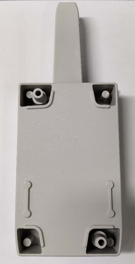
Click to zoom
Application Details
- Equipment Class
- CYY - Communications Receiver used w/Pt 15 Transmitter
- Date of Grant
- Apr 20, 2021
- Application Purpose
- Original Equipment
- Date of Application
- Apr 20, 2021
- Equipment Note
- CONNECT4 CC CONNECT CC-CAM CONNECT CC-ACT CONNECT CC-CIS
- Frequency Range
- 868.32000000 - 868.32000000
- Company
- JCM Technologies, S.A.U.
- Country
- Spain
Documents & Files
Document Text
Text extracted from the exhibit documents filed with the FCC. Open a document above to read the original.
Users Manual
CONNECT4 CC User Manual / Manuel de l’utilisateur Table of contents / Index I mportant safety instructions3 Use of the equi pment3 I ntroduction4 I nstallation and connections 4 Operating5 Wi egand formats:5 Confi gurati on and connecti on for the di fferent protocol s6 * Faci l i ty Code: SW1 -8 , 0 = OFF/1 = ON6 Groups9 Group confi gurati on9 Notes1 0 Technical data1 1 Regulatory Data1 1 FCC / ISED Compl i ance1 1 Consignes importantes de sécurité1 2 Uti l i sati on de l 'apparei l1 2 I ntroduction1 3 I nstallation et connections1 3 Fonctionnement1 4 Formats Wi egand :1 4 Confi gurati on et connexi on pour l es di fférents protocol es1 5 * Code d’i nstal l ati on : SW1 -8 , 0 = ÉTEINT/1 = ALLUMÉ1 5 Groupes1 8 Confi gurati on des groupes1 8 Notes 1 9 Données techniques2 0 Données réglementaires2 0 Conformi té FCC / ISED2 0 jcm technologies 2 Important safety instructions Disconnect the power supply whenever you proceed with the installation or repair of the equipment. In compl i ance wi th the European Low Vol tage Di recti ve, we i nform you of the fol l owi ng requi rements: •When thedevicesremain permanentlyconnected, an easilyaccessibleconnecting devicemust beincorporatedinto thewiring. •Thissystem must onlybeinstalledbyqqualifiedprofessionalsthat haveexperiencewithautomatedgaragedoorsandknow- ledgeof therelevant European standards. •Theuserinstructionsforthisdevicemust alwaysbein theuser’spossession. •Theoperating frequencyof thereceiverdoesnot interferein anywaywiththe868 MHzremotecontrolsystems. Useof theequipment Thi s devi ce i s desi gned for appl i cati ons wi th an automated garage door. It i s not guaranteed for the di rect acti vati on of devi ces other than those speci fi ed. The manufacturer reserves the ri ght to change the speci fi cati ons of the devi ce wi thout warni ng. jcm technologies 3 Introduction Mul ti protocol recei ver compati bl e wi th MOTION transmi tters. Codi fi es the transmi tter si gnal i n two di fferent protocol s accordi ng to i ts confi gurati on: Wi egand 2 6 and Wi egand 3 7 . Installation and connections Attach the rear part of the housi ng to the wal l usi ng the pl ugs and screws suppl i ed. Pass the cabl es through the bottom of the recei ver. Connect the power cabl es to the termi nal s marked on the mother board, as i ndi cated. Fi x the recei ver front to the rear part usi ng the screws suppl i ed. jcm technologies 4 Operating The CONNECT-MCH FC i s a recei ver that wi l l pass i ncomi ng frames from remote control s vi a a sel ected channel (1 out of 4 ) towards a central (Led TX= ON). The channel depends on the button that i s pressed on the remote control . The frame that i s del i vered at D0 -D1 of channel CH1 /CH2 /CH3 /CH4 i s of type WIEGAND. Wiegand formats: W2 6 , NO Facility Code : •1 bit -Even parity(of next 12 bits) •4 bit – Zeros •20 bit – Remotecontrolnumber, complete. •1 bit -Oddparity(of last 12 bits) W2 6 , with Facility CODE: •1 bit -Even parity(of next 12 bits) •8 bit – FacilityCodeasset by8 switches. •16 bit – Remotecontrolnumber, lowerpart (*) •1 bit -Oddparity(of last 12 bits) (* ): up to 6 5 5 3 6 remote control s wi th consecuti ve numbers may be used. W3 7 : •1 bit -Even parity(of next 18 bits) •8 bit – Counter •2 bit – Zeros •3 bit – Substitute •3 bit – ChannelDCS •19 bit – Remotecontrolnumber •1 bit -Oddparity(of last 18 bits) jcm technologies 5 Configuration and connection for the different protocols Swi tch SW1 al l ows to sel ect the short W2 6 (SW1 = OFF) or the l ong W3 7 (SW1 = ON) format. In case the short W2 6 i s sel ected, the content of the frame may be NO FC (SW2 = OFF), or i ncl ude a so cal l ed Faci l i ty Code (SW2 = ON). In thi s case, the val ue of the Faci l i ty Code i n Bi nary i s set by 8 swi tches, each one defi ni ng ei ther a 0 = OFF or 1 = ON. ProtocolPower Remote Control Signal OutputSW1SW2 Facility Code 1 to 8 BitsFRAME FORMAT W26 NO Facility Code +- Button 1/2/3/4 CH1/2/3/4 D0-D1 OFFOFFdon't care EP(1)-Zeros(4)-Remote Control Number(20)-OP(1) W37+- Button 1/2/3/4 CH1/2/3/4 D0-D1 ON don't care don't care EP(1)-Counter(8)-Zeros(2)-Sub(3)- DCS(3)-Remote ControlNumber(19)- OP(1) W26 with Facility Code +- Button 1/2/3/4 CH1/2/3/4 D0-D1 OFFON mode Facility Code* EP(1)-FacilityCode(8)-Remote Control Number(16)-OP(1) * Facility Code: SW1-8, 0=OFF/1=ON DECBINDECBINDECBINDECBIN 000000000160001000032001000004800110000 100000001170001000133001000014900110001 200000010180001001034001000105000110010 300000011190001001135001000115100110011 400000100200001010036001001005200110100 500000101210001010137001001015300110101 600000110220001011038001001105400110110 700000111230001011139001001115500110111 800001000240001100040001010005600111000 900001001250001100141001010015700111001 1000001010260001101042001010105800111010 1100001011270001101143001010115900111011 1200001100280001110044001011006000111100 1300001101290001110145001011016100111101 1400001110300001111046001011106200111110 1500001111310001111147001011116300111111 jcm technologies 6 DECBINDECBINDECBINDECBIN 64010000008001010000960110000011201110000 65010000018101010001970110000111301110001 66010000108201010010980110001011401110010 67010000118301010011990110001111501110011 680100010084010101001000110010011601110100 690100010185010101011010110010111701110101 700100011086010101101020110011011801110110 710100011187010101111030110011111901110111 720100100088010110001040110100012001111000 730100100189010110011050110100112101111001 740100101090010110101060110101012201111010 750100101191010110111070110101112301111011 760100110092010111001080110110012401111100 770100110193010111011090110110112501111101 780100111094010111101100110111012601111110 790100111195010111111110110111112701111111 DECBINDECBINDECBINDECBIN 12810000000144100100001601010000017610110000 12910000001145100100011611010000117710110001 13010000010146100100101621010001017810110010 13110000011147100100111631010001117910110011 13210000100148100101001641010010018010110100 1331000010114910010…
Text truncated - open the document above for the full version.
External Photos
Photographs – external_ CONNECT4 CC / CONNECT4 CC-ACT / CONNECT4 CC-CIS
ID Label/Location Info
Product label design_ CONNECT4 CC, CONNECT4 CC -ACT, CONNECT4 CC-CIS
Internal Photos
Photographs – internal_ CONNECT4 CC / CONNECT 4 CC-CAM / CONNECT4 CC- ACT / CONNECT4 CC-C IS
Test Report
DEKRA Testing and Certification, S.A.U. Parque Tecnológico de Andalucía, c/ Severo Ochoa nº 2 · 29590 Campanillas · Málaga · España C.I.F. A29 507 456 Report No: 66381REM.001A1 2021-04-20 Test report No: NIE: 66381REM.001A1 Test report FCC Rules and Regulations CFR 47, Part 15, Subpart B (10-1-19 Edition) & ICES-003 Issue 7 (October 2020) (*) Identification of item tested Receiver (*) Trademark JCM TECHNOLOGIES, S.A. (*) Model and /or type reference CONNECT4 CC; CONNECT CC-CAM; CONNECT CC- ACT; CONNECT CC-CIS Other identification of the product HW Version: 2000851_00 (S-CONNECT-MCH FC) SW Version: CONNECT_MCH_FC_01020000 FCC ID: U5Z-CONNECT4CC IC ID: 8572A-CONNECT4CC (*) Features Wiegand Manufacturer JCM TECHNOLOGIES, S.A. C/Costa d’en Paratge, 6B 08500, Vic, Barcelona Test method requested, standard FCC Rules and Regulations CFR 47, Part 15, Subpart B (10-1-19 Edition) & ICES-003 Issue 7 (October 2020) Summary IN COMPLIANCE Approved by (name / position & signature) Rafael López EMC Consumer & RF Lab. Manager Date of issue 2021-04-20 Report template No FDT08_23 (*) “Data provided by the client” DEKRA Testing and Certification, S.A.U. Parque Tecnológico de Andalucía, c/ Severo Ochoa nº 2 · 29590 Campanillas · Málaga · España C.I.F. A29 507 456 Report No: 66381REM.001A1 Page 2 of 21 2021-04-20 Index ACRONYMS ................................................................................................................................................................. 3 COMPETENCES AND GUARANTEES ....................................................................................................................... 3 GENERAL CONDITIONS ............................................................................................................................................. 4 UNCERTAINTY ............................................................................................................................................................ 4 DATA PROVIDED BY THE CLIENT ............................................................................................................................ 4 USAGE OF SAMPLES ................................................................................................................................................. 6 TEST SAMPLE DESCRIPTION ................................................................................................................................... 7 IDENTIFICATION OF THE CLIENT ............................................................................................................................. 8 TESTING PERIOD AND PLACE .................................................................................................................................. 8 DOCUMENT HISTORY ................................................................................................................................................ 8 ENVIRONMENTAL CONDITIONS ............................................................................................................................... 9 REMARKS AND COMMENTS ................................................................................................................................... 10 TESTING VERDICTS ................................................................................................................................................. 10 LIST OF EQUIPMENT USED DURING THE TEST ................................................................................................... 10 SUMMARY .................................................................................................................................................................. 11 APPENDIX A: TEST RESULTS ................................................................................................................................. 12 DEKRA Testing and Certification, S.A.U. Parque Tecnológico de Andalucía, c/ Severo Ochoa nº 2 · 29590 Campanillas · Málaga · España C.I.F. A29 507 456 Report No: 66381REM.001A1 Page 3 of 21 2021-04-20 Acronyms Acronym ID Acronym Description Avg Radiated Average Level Avg Conducted Average Level Az Azimuth CPL Zones / Coupling Cables Code EMC Test Code Freq Frequency Freq Rng Frequency Range H Height Line Conducted Emissions - Tested Line MP Measurement Point Max Conducted Maximum Level MaxPeak Radiated Maximum Peak Level OM Operation Mode Pol Polarization QuasiPeak Conducted Quasi Peak Level QuasiPeak Radiated Quasi Peak Level S/ Sample V Verdict Volt Immunity Lvl Voltage Immunity Severity Level Volt Immunity Type Voltage Immunity Type Competences and guarantees DEKRA Testing and Certification S.A.U. is a testing laboratory accredited by the National Accreditation Body (ENAC -Entidad Nacional de Acreditación), to perform the tests indicated in the Certificate No. 51/LE 147. In order to assure the traceability to other national and international laboratories, DEKRA Testing and Certification S.A.U. has a calibration and maintenance program for its measurement equipment. DEKRA Testing and Certification S.A.U. guarantees the reliability of the data presented in this report, which is the result of the measurements and the tests performed to the item under test on the date and under the conditions stated on the report and, it is based on the knowledge and technical facilities available at DEKRA Testing and Certification S.A.U. at the time of performance of the test. DEKRA Testing and Certification S.A.U. is liable to the client for the maintenance of the confidentiality of all information related to the item under test and the results of the test. The results presented in this Test Report apply only to the particular item under test established in this document. IMPORTANT: No parts of this report may be reproduced or quoted out of context, in any form or by any means, except in full, without the previous written permission of DEKRA Testing and Certification S.A.U. DEKRA Testing and Cert…
Text truncated - open the document above for the full version.
Test Setup Photos
DEKRA Testing and Certification, S.A.U. Parque Tecnológico de Andalucía, c/ Severo Ochoa nº 2 · 29590 Campanillas · Málaga · España C.I.F. A29 507 456 Report No: 66381REM.001A1 2021-04-20 Photographs
Contact Information
Applicant
Juan Capdevila(General Manager)
Test Firm
DEKRA Testing and Certification, S.A.U.Rafael Lopez Martin
Technical Specifications
| # | Rule Parts | Frequency Range | Power Output |
|---|---|---|---|
| 1 | 15B | 868.32 MHz - 868.32 MHz | - |
Other Applications from JCM Technologies, S.A.U.
U5Z-RB-TX20C
Jul 25, 2024Safety edge wireless system consisting in a transmitter
Equipment Class
DXX - Part 15 Low Power Communication Device Transmitter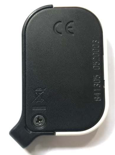
U5Z-GOMINI
Mar 14, 2021868 MHZ radio transmitter
Equipment Class
DSC - Part 15 Security/Remote Control Transmitter
U5Z-RB-P-RX10C
Apr 20, 2020Safety edge wireless receiver
Equipment Class
DSC - Part 15 Security/Remote Control Transmitter
U5Z-FREE15R
Apr 02, 2012RFID Reader
Equipment Class
DCD - Part 15 Low Power Transmitter Below 1705 kHz
U5Z-BASE5001B-2B
Dec 17, 2011Receiver for security gate system
Equipment Class
CYY - Communications Receiver used w/Pt 15 Transmitter