U5Z-RB-P-RX10CSafety edge wireless receiver
JCM Technologies, S.A.U.
Click to zoom
Application Details
- Equipment Class
- DSC - Part 15 Security/Remote Control Transmitter
- Date of Grant
- Apr 20, 2020
- Application Purpose
- Original Equipment
- Date of Application
- Apr 20, 2020
- Equipment Note
- Safety edge wireless receiver
- Frequency Range
- 902.30000000 - 927.70000000
- Company
- JCM Technologies, S.A.U.
- Country
- Spain
Documents & Files
Document Text
Text extracted from the exhibit documents filed with the FCC. Open a document above to read the original.
Users Manual
Miller Edge, Inc. • www.milleredge.com • [email protected] • East Coast: 800-220-4422 • West Coast: 800-887-3343 INSTALLATION INSTRUCTIONS Model: RB-P-K10 IMPORTANT: READ AND UNDERSTAND ALL INSTRUCTIONS BEFORE BEGINNING INSTALLATION The Miller Edge RBand Monitored Door Edge Transmitter/Receiver system is intended to provide a wireless connection between a monitored sensing edge and a motorized operator installed with a garage door or grille. RBand meets the 2016 UL 325 requirements for monitored devices and has been certified as a UL 325 Recognized Component. It is designed for use with operators that comply with 2016 UL 325 using a Miller Edge 10K Sensing Edge. 1. PARTS LIST Kit Contents: 1. RBand Edge Transmitter (RB-TX10C) 2. RBand Door Edge Receiver (RB-P-RX10C) 3. (2) 3.6V AA lithium batteries* 4. (4) #6 pan head transmitter mounting screws *Replacement 3.6V AA lithium batteries can be purchased at your local electronics store or via Miller Edge. Required: • 1/8” flat blade screwdriver • 1/4” flat blade screwdriver • Miller Edge 10K (T2/blue band) Sensing Edge Recommended: • Multi-meter capable of reading 10KΩ • Mounting screws as required for receiver 2. RECEIVER INSTALLATION 2-1. Turn off power to the door operator. 2-2. Remove Receiver cover and mount the receiver base near the operator, where it will be in line of sight with the transmitter for the entire range of travel [IMAGE 1]. 2-3. Connect power (12-24 VAC/DC) to the terminals marked power, noting the +/- polarity. 24 VAC power can be connected either way not polarity sensitive [IMAGE 2]. 2-4. Connect both OSE1_2FA and OSE1_2FB to the photo-eye inputs on the operator. OSE1_3F is not used. 2-5. Replace the Receiver cover and turn on power to the operator. Note: it takes ~5 seconds for the Receiver to initialize. Note: RBand 10K Door Edge Receiver is compatible with up to 3 RBand Transmitters. RBAND MONITORED DOOR EDGE TRANSMITTER/RECEIVER RB-P-K10_Install_20200115 IMAGE 1. Door Installation with RBand Transmitter & Receiver OPERATOR RBAND RECEIVER MOUNTED BELOW OPERATOR WITH ANTENNA POINTED DOWN ANTENNA WIRING RBAND TRANSMITTER MOUNTED ABOVE SENSING EDGE SENSING EDGE DRAFT Miller Edge, Inc. • www.milleredge.com • [email protected] • East Coast: 800-220-4422 • West Coast: 800-887-3343 IMAGE 2. RBand Door Edge Receiver PCB & Connections LED INDICATORS Initial Power • No Transmitters Programmed: R1 LED on R1 LED (1 edge connected) • Programmed: Off • Fault Condition: On Check LED • Programmed: Check LED flashes every 5 seconds R2 LED • Not used DIP SWITCH SETTINGS ON 1 2 3 Leave switches in factory default settings (all on). 7-PIN CONNECTOR +12/24 VAC/DC Constant power source -12/24 VAC/DC Constant power source ground OSE1_3F Not used OSE1_2FA P.E. input terminal OSE1_2FB P.E. input terminal or common NC2 Normally closed COM2 Open relay ANT R2 R1 CHECK GND PROG ON 1 2 3 12/24 VAC/DC OSE1_3F + - NC2 COM2 OSE1_2FA OSE1_2FB MR PROGRAM BUTTON CHECK LED & BUTTON REMOVABLE 7-PIN CONNECTORDIP SWITCHES RELAY LEDS ANTENNA TERMINAL BLOCK ANTENNA DRAFT Miller Edge, Inc. • www.milleredge.com • [email protected] • East Coast: 800-220-4422 • West Coast: 800-887-3343 IMAGE 3. RBand Edge Transmitter PCB & Connections 3. TRANSMITTER: PROGRAM MODE 3-1. Confirm the Receiver is powered up. Prior to mounting the Transmitter, remove the cover and insert the batteries, noting their polarity [IMAGE 3]. The green LED should blink to indicate that the Transmitter has not been associated with the Receiver yet. 3-2. To enter learn mode, press and hold the Receiver program button [IMAGE 2] for ~2 seconds until the R1 LED turns on, then release the button. 3-3. Press the Transmitter program button [IMAGE 3] for ~2 seconds. The Receiver should beep. Wait 10 seconds for an additional beep to indicate that programming is complete. 3-4. Repeat 3-2 and 3-3 for up to 3 Transmitters. 4. TRANSMITTER: INSTALL & TEST 4-1. Strip back approximately 2 inches of outer covering of sensing edge cable, then feed through the Transmitter strain relief fitting [IMAGE 3]. Connect the two sensing edge wires to the removable terminal. Dress the wires with a small service loop and tighten the strain relief. Mount unit utilizing the mounting holes at the 4 corners of the Transmitter box. Return lid to Transmitter, noting the alignment pin [IMAGE 3]. 4-2. Test the sensing edge for functionality: press the sensing edge and the Receiver R1 LED will turn on. 5. TROUBLESHOOTING If the Receiver does not react to the Transmitter, you can check the RF signal strength: 5-1. Press the check button on the Receiver for ~2 seconds [IMAGE 2]; 4 beeps will be heard. You then will hear a beep every 1-1/2 seconds during the check process. Wait about 30 seconds; if no other beeps occur, your system is functioning. 3 quick beeps indicates a communication error. 5-2. Activate the sensing edge and observe the check LED; 3-5 flashes is ideal. Less than 3 flashes means there is a weak signal. 5-3. To exit check function, press the check button again, or the system will time-out after 5 minutes. There will be a series of beeps heard upon exiting. 6. ERASING THE RECEIVER Erase the Receiver if you need to replace a Transmitter or you have any other programming problems: 6-1. Use a screwdriver to short the two pins next to the DIP switch marked MR [IMAGE 2]. 6-2. While shorting the pins, press and hold the program button for several seconds; you will hear a series of 10 beeps following by a rapid chirping sound. 6-3. When the chirping stops, release the program button. Wait ~10 seconds and you will hear 2 beeps. The Receiver is now ready to be reprogrammed. PROGRAM BUTTON REMOVABLE SENSING EDGE TERMINAL BLOCK (4) CORNER MOUNTING HOLES GREEN LED ALIGNMENT PIN STRAIN RELIEF FITTING ALIGNMENT PIN (2) 3.6V AA LITHIUM BATTERIES DRAFT Miller Edge, Inc. • www.milleredge.com • [email protected] • East Coast: 800-220-4422 • West Coast: 800-887-3343 7. TRANSMITTER: SPECIFICATIONS & CONTROLS Trans…
Text truncated - open the document above for the full version.
Cover Letter(s)
FCB012_02 //DEKRA Testing and Certification, S.A.U. // www.dekra-product-safety.com/wireless Date: April 13th 2020 DEKRA Testing and Certification, S.A.U. Parque Tecnológico de Andalucía C/ Severo Ochoa 2 & 6 29590 Campanillas Málaga, España Ref: Confidentiality request for FCC ID: U5Z-RB-P-RX10C To whom it may concern: Pursuant to §0.457(d)(1)(ii) and §0.459 of the Commission’s Rules (47 C.F.R.) and §552 (b)(4) of the Freedom of Information Act, JCM Technologies, S.A. hereby request requests that a part of the subject FCC application be held confidential to avoid release of sensitive information of the product to the public. For the product stated above, we request that the following information be withheld from public disclose: Type of Confidentiality Requested Exhibit Short Term Permanent Block Diagrams Short Term External Photos Short Term Internal Photos Short Term Permanent Operation Description Short Term Permanent Parts List & Placement/BOM Short Term Permanent Tune-Up Procedure Short Term Permanent Schematics Short Term Test Setup Photos Short Term User’s Manual Permanent Confidentiality: The above materials contain trade secrets and proprietary information not customarily released to the public. The public disclosure of these matters might be harmful to us and provide unjustified benefits to our competitors. Short-Term Confidentiality: We hereby request short-term confidentiality for the product stated above to avoid premature release of sensitive information prior to marketing or release of the product to the public. Release date of short term confidentiality is: 45 days from grant date marked 90 days from grant date marked 135 days from grant date marked 180 days from grant date marked Specific date: We are also aware that we are responsible to notify DEKRA in the event information regarding the product or the product is made available to the public. DEKRA will then release the documents listed above for public disclosure pursuant to FCC Public Notice DA 04-1705. Sincerely, __________________________ By: Juan Capdevila Title: General Manager Company: JCM Technologies S.A. Telephone: +34938833231 e-mail: [email protected]
Cover Letter(s)
FCB034_00 //DEKRA Testing and Certification, S.A.U. // www.dekra-product-safety.com/wireless Date: April 13th 2020 DEKRA Testing and Certification, S.A.U. Parque Tecnológico de Andalucía C/ Severo Ochoa 2 & 6 29590 Campanillas Málaga, España Ref: sDoC declaration letter for equipment with FCC ID: U5Z-RB-P-RX10C Pursuant to §15.101 of the Commission’s Rules (47 C.F.R.), JCM Technologies, S.A. hereby declare that the device above mentioned is classified under the following equipment class/classes: JAB Part 15 Class B Digital Device JAD Part 15 Class A Digital Device JAV Other Non-Digital SDoC Devices JBP Part 15 Class B Computing Device/Personal Computer JBC Part 15 Class B Computing Device/Personal Computer CXX Communications Rcvr for use w/ licensed Tx and CBs CRR Superregenerative Receiver CYY Communications Receiver used w/Pt 15 Transmitter HID Part 15 TV Interface Device And will follow the Authorization procedure Supplier’s Declaration of Conformity prior to the initiation of marketing. Sincerely, __________________________ By: Juan Capdevila Title: General Manager Company: JCM Technologies S.A. Telephone: +34938833231 e-mail: [email protected]
External Photos
EXTERNAL PHOTOS RB-P-RX10C Model: RB-P-RX10C FCC ID: U5Z-RB-P-RX10C
ID Label/Location Info
EXTERNAL PHOTOS RB-P-RX10C Model: RB-P-RX10C FCC ID: U5Z-RB-P-RX10C
Internal Photos
INTERNAL PHOTOS RB-P-RX10C Model: RB-P-RX10C FCC ID: U5Z-RB-P-RX10C
RF Exposure Info
DEKRA Testing and Certification, S.A.U. Parque Tecnológico de Andalucía, c/ Severo Ochoa nº 2 · 29590 Campanillas · Málaga · España C.I.F. A29 507 456 Report No: (NIE) 63682RAN.001 2020-02-13 Test report No: NIE: 63682RAN.001 Assessment report RF EXPOSURE REPORT ACCORDING TO FCC 47 CFR Part 2.1091 (*) Identification of item under evaluation Safety edge wireless receiver (*) Trademark JCM (*) Model and /or type reference RB-P-RX10C Other identification of the product FCC ID: U5Z-RB-P-RX10C HW version: S-RB3OSE916-EL SW version: RB3ROSER_ULMEX_02.04.11.01 (*) Features Power supply: 12/24V ac/dc Power supply range: 9-35Vdc / 8-28Vac Frequency: Multifrequency system 916MHz auto- adjustable Operating consumption: Max 100mA Radiated power < 25mW Range (in open field): 50m Manufacturer JCM TECHNOLOGIES, S.A. C/Costa d’en paratge, 6B, 08500, Vic, Barcelona (SPAIN) Test method requested, standard FCC 47 CFR Part 2.1091 Radiofrequency radiation exposure evaluation: mobile devices. IEEE Std C95.3 TM -2002 (R2008). IEEE Recommended Practice for Measurements and Computations of Radio Frequency Electromagnetic Fields With Respect to Human Exposure to Such Fields, 100 kHz–300 GHz Summary IN COMPLIANCE Approved by (name / position & signature) Miguel Lacave Antennas Lab Manager Date of issue 2020-02-13 Report template No FAN36_01 (*) “Data provided by the client” DEKRA Testing and Certification, S.A.U. Parque Tecnológico de Andalucía, c/ Severo Ochoa nº 2 · 29590 Campanillas · Málaga · España C.I.F. A29 507 456 Report No: (NIE) 63682RAN.001 Page 2 of 7 2020-02-13 Index Competences and guarantees .................................................................................................... 3 General conditions ...................................................................................................................... 3 Data provided by the client .......................................................................................................... 3 Identification of the client............................................................................................................. 3 Document history ........................................................................................................................ 3 General description of the device under evaluation ..................................................................... 4 RF Exposure Assessment result and verdict ............................................................................... 4 Appendix A: FCC RF Exposure information ................................................................................ 5 FCC RF Exposure evaluation ................................................................................................. 6 FCC MPE Evaluation ............................................................................................................. 7 DEKRA Testing and Certification, S.A.U. Parque Tecnológico de Andalucía, c/ Severo Ochoa nº 2 · 29590 Campanillas · Málaga · España C.I.F. A29 507 456 Report No: (NIE) 63682RAN.001 Page 3 of 7 2020-02-13 Competences and guarantees In order to assure the traceability to other national and international laboratories, DEKRA Testing and Certification, S.A.U. has a calibration and maintenance program for its measurement equipment. DEKRA Testing and Certification, S.A.U. guarantees the reliability of the data presented in this report, which is the result of the measurements and the tests performed to the item under test on the date and under the conditions stated on the report and, it is based on the knowledge and technical facilities available at DEKRA Testing and Certification, S.A.U. at the time of performance of the test. DEKRA Testing and Certification, S.A.U. is liable to the client for the maintenance of the confidentiality of all information related to the item under test and the results of the test. The results presented in this Assessment Report apply only to the particular item under test established in this document. IMPORTANT: No parts of this report may be reproduced or quoted out of context, in any form or by any means, except in full, without the previous written permission of DEKRA Testing and Certification, S.A.U. General conditions 1. This report is only referred to the item that has undergone the assessment. 2. This report does not constitute or imply on its own an approval of the product by the Certification Bodies or competent Authorities. 3. This document is only valid if complete; no partial reproduction can be made without previous written permission of DEKRA Testing and Certification, S.A.U. 4. This test report cannot be used partially or in full for publicity and/or promotional purposes without previous written permission of DEKRA Testing and Certification, S.A.U. and the Accreditation Bodies Data provided by the client The following data has been provided by the client: 1. Information relating to the description of the sample ("Identification of the item tested", "Trademark", "Model and/or type reference tested"). 2. Maximum output power and maximum antenna gain information. 3. The device consists of a 916MHz multifrequency receiver for working with a safety edge wireless transmitter. DEKRA Testing and Certification S.A.U. declines any responsibility with respect to the information provided by the client and that may affect the validity of results. Identification of the client JCM TECHNOLOGIES, S.A. C/Costa d’en paratge, 6B, 08500, Vic, Barcelona (SPAIN). Document history Report number Date Description 63682RAN.001 2020-02-13 First release DEKRA Testing and Certification, S.A.U. Parque Tecnológico de Andalucía, c/ Severo Ochoa nº 2 · 29590 Campanillas · Málaga · España C.I.F. A29 507 456 Report No: (NIE) 63682RAN.001 Page 4 of 7 2020-02-13 General description of the device under evaluation The device under evaluation consists of a 916MHz multifrequency receiver for working with a safety edge wireless transmitter. According to t…
Text truncated - open the document above for the full version.
Test Report
DEKRA Testing and Certification, S.A.U. Parque Tecnológico de Andalucía, c/ Severo Ochoa nº 2 · 29590 Campanillas · Málaga · España C.I.F. A29 507 456 Report No: (NIE) 63682RRF.001 2020-02-24 Test report No: NIE: 63682RRF.001 Partial Test report USA FCC Part 15.249 & 15.209 CANADA RSS-210, RSS-Gen Radio Frequency Devices. Operation within the bands 902 - 928 MHz, 2400 -2483.5 MHz, 5725 - 5875 MHz, and 24.0 – 24.25 GHz. (*) Identification of item tested Safety edge wireless receiver (*) Trademark JCM (*) Model and /or type reference RB-P-RX10C Other identification of the product FCC ID: U5Z-RB-P-RX10C HW Version: S-RB3OSE916-EL SW Version: RB3ROSER_ULMEX_02.04.11.01 (*) Features Power supply: 12/24V ac/dc Power supply range: 9-35Vdc / 8-28Vac Frequency: Multifrequency system 916MHz auto- adjustable Operating consumption: Max 100mA Radiated power < 25mW Range (in open field): 50m Applicant JCM TECHNOLOGIES, S.A. C/Costa d’en paratge, 6B, 08500, Vic, Barcelona (SPAIN) Test method requested, standard USA FCC Part 15.249 10-1-18 Edition: Operation within the bands 902 - 928 MHz, 2400 -2483.5 MHz, 5725 - 5875 MHz, and 24.0 – 24.25 GHz. USA FCC Part 15.209 10-1-18 Edition: Radiated emission limits; general requirements. CANADA RSS-210 Issue 9 (August 2016). CANADA RSS-Gen Issue 5 (April 2018). ANSI C63.10-2013: American National Standard for Testing Unlicensed Wireless Devices. DEKRA Testing and Certification, S.A.U. Parque Tecnológico de Andalucía, c/ Severo Ochoa nº 2 · 29590 Campanillas · Málaga · España C.I.F. A29 507 456 Report No: (NIE) 63682RRF.001 Page 2 of 26 2020-02-24 Approved by (name / position & signature) Jose Carlos Luque RF Lab. Supervisor Date of issue 2020-02-24 Report template No FDT08_22 (*) “Data provided by the client” DEKRA Testing and Certification, S.A.U. Parque Tecnológico de Andalucía, c/ Severo Ochoa nº 2 · 29590 Campanillas · Málaga · España C.I.F. A29 507 456 Report No: (NIE) 63682RRF.001 Page 3 of 26 2020-02-24 Index Competences and guarantees .................................................................................................... 4 General conditions ...................................................................................................................... 4 Uncertainty ................................................................................................................................. 4 Data provided by the client .......................................................................................................... 4 Usage of samples ....................................................................................................................... 5 Test sample description .............................................................................................................. 5 Identification of the client............................................................................................................. 7 Testing period and place ............................................................................................................. 7 Document history ........................................................................................................................ 7 Environmental conditions ............................................................................................................ 7 Remarks and comments ............................................................................................................. 8 Testing verdicts ........................................................................................................................... 8 Summary .................................................................................................................................... 8 Appendix A: Test results ............................................................................................................. 9 DEKRA Testing and Certification, S.A.U. Parque Tecnológico de Andalucía, c/ Severo Ochoa nº 2 · 29590 Campanillas · Málaga · España C.I.F. A29 507 456 Report No: (NIE) 63682RRF.001 Page 4 of 26 2020-02-24 Competences and guarantees DEKRA Testing and Certification S.A.U. is a testing laboratory accredited by the National Accreditation Body (ENAC -Entidad Nacional de Acreditación), to perform the tests indicated in the Certificate No. 51/LE 147. DEKRA Testing and Certification is a FCC-recognized accredited testing laboratory with appropriate scope of accreditation that include testing performed in this test report. DEKRA Testing and Certification is an ISED-recognized accredited testing laboratory with appropriate scope of accreditation that include testing performed in this test report In order to assure the traceability to other national and international laboratories, DEKRA Testing and Certification S.A.U. has a calibration and maintenance program for its measurement equipment. DEKRA Testing and Certification S.A.U. guarantees the reliability of the data presented in this report, which is the result of the measurements and the tests performed to the item under test on the date and under the conditions stated on the report and, it is based on the knowledge and technical facilities available at DEKRA Testing and Certification S.A.U. at the time of performance of the test. DEKRA Testing and Certification S.A.U. is liable to the client for the maintenance of the confidentiality of all information related to the item under test and the results of the test. The results presented in this Test Report apply only to the particular item under test established in this document. IMPORTANT: No parts of this report may be reproduced or quoted out of context, in any form or by any means, except in full, without the previous written permission of DEKRA Testing and Certification S.A.U. General conditions 1. This report is only referred to the item that has undergone the test. 2. This report does not constitute or imply on its own an approval of the product by the Cert…
Text truncated - open the document above for the full version.
Test Report
CMC Centro Misure Compatibilità S.r.l. Via dell’Elettronica, 12/C 36016 Thiene (VI) – ITALY Tel./Fax +39 0445 367702 www.cmclab.it - [email protected] Independent Testing Laboratory Accredited by ACCREDIA according to UNI CEI EN ISO/IEC 17025 cert. nr. 0168 Test report R15182602 Rev. 1.0 Order M151826 page 1 of 48 LAB N° 0168 TEST REPORT nr. R15182602 Federal Communication Commission (FCC) Test item Description ........................ : RADIOBAND RECEIVER USING OSE INTERFACE FROM RBAND TO CONTROL PANEL Trademark ......................... : JCM TECHNOLOGIES Model/Type ...................... : RB3 OSE916 FCC ID ................................ : U5Z-RB3OSE916 Test Specification Standard ........................... : FCC Rules & Regulations, Title 47:2014 Part 15 paragraph(s): 203, 204, 207, 209 and 231 Client’s name .............. : JCM TECHNOLOGIES S.A. Address .............................. : Bisbe Morgades, 46 (Baixos) – 08500 Vic – SPAIN Manufacturer’s name : Same as client Address .............................. : -- Report Tested by ........................... : A. Bertezzolo – Technician Approved by .................... : R. Beghetto – Laboratory Manager Date of issue ..................... : 22.02.16 Contents ............................ : 48 pages This test report shall not be reproduced except in full without the written approval of CMC. The test results presented in this report relate only to the item tested. CMC Centro Misure Compatibilità S.r.l. Via dell’Elettronica, 12/C 36016 Thiene (VI) Test report R15182602 Rev. 1.0 Order M151826 page 2 of 48 LAB N° 0168 Index 1. SUMMARY ..................................................................................................................................................3 2. DESCRIPTION OF EQUIPMENT UNDER TEST (EUT) .....................................................................................4 2.1 TEST SITE .................................................................................................................................................... 6 3. TESTING AND SAMPLING ..........................................................................................................................6 4. OPERATIVE CONDITIONS ..........................................................................................................................6 5. PHOTOGRAPH(S) OF EUT ..........................................................................................................................7 5.1 PHOTOGRAPH(S) OF EUT ........................................................................................................................... 7 6. EQUIPMENT LIST .........................................................................................................................................8 7. MEASUREMENT UNCERTAINTY ..................................................................................................................9 8. REFERENCE DOCUMENTS........................................................................................................................10 9. DEVIATION FROM TEST SPECIFICATION .................................................................................................11 10. TEST CASE VERDICTS ...........................................................................................................................11 11. RESULTS ................................................................................................................................................12 11.1 ANTENNA REQUIREMENTS ......................................................................................................................... 13 11.2 CONDUCTED EMISSIONS ........................................................................................................................... 14 11.3 RADIATED EMISSIONS ................................................................................................................................ 18 11.4 FUNDAMENTAL AND SPURIOUS EMISSION (≤ 1 GHZ) .................................................................................. 32 11.5 SPURIOUS EMISSION (> 1 GHZ) ................................................................................................................ 37 11.6 OCCUPIED CHANNEL BANDWIDTH ............................................................................................................ 40 11.7 PERIODIC OPERATION CHARACTERISTICS .................................................................................................. 45 ANNEX 1: photographs of test setup CMC Centro Misure Compatibilità S.r.l. Via dell’Elettronica, 12/C 36016 Thiene (VI) Test report R15182602 Rev. 1.0 Order M151826 page 3 of 48 LAB N° 0168 1. Summary Standard: FCC Rules & Regulations, Title 47:2014 Part 15 paragraph(s): 203, 204, 207, 209 and 231 Test specifications Environmental Phenomena Tests sequence Result Part 15.203 Antenna requirements 1 Complies Part 15.207 Conducted emissions 2 Complies Part 15.209 Radiated emissions 3 Complies Part 15.209 and 15.231(b) Fundamental and spurious emissions (≤ 1 GHz) 4 Complies Part 15.209 and 15.231 Spurious emissions (> 1 GHz) 5 Complies Part 15.231(c) Occupied channel bandwidth 6 Complies Part 15.231(a3) Periodic operation characteristics 7 Complies The Test Report was given to the Client representatives for necessary documentation of ratification of the tested equipment and it is valid for the FCC certification CMC Centro Misure Compatibilità S.r.l. Via dell’Elettronica, 12/C 36016 Thiene (VI) Test report R15182602 Rev. 1.0 Order M151826 page 4 of 48 LAB N° 0168 2. Description of Equipment under test (EUT) Power supply .................................................................. : 12/24 Vdc Tests performed on 12 Vdc power supply Serial Number ................................................................. : -- Type of equipment ..................................................... : Transmitter Unit Rec…
Text truncated - open the document above for the full version.
Test Setup Photos
DEKRA Testing and Certification, S.A.U. Parque Tecnológico de Andalucía, c/ Severo Ochoa nº 2 · 29590 Campanillas · Málaga · España C.I.F. A29 507 456 Report No: (NIE) 63682RRF.001 Page 1 of 5 2020-02-24 Appendix B: Photographs DEKRA Testing and Certification, S.A.U. Parque Tecnológico de Andalucía, c/ Severo Ochoa nº 2 · 29590 Campanillas · Málaga · España C.I.F. A29 507 456 Report No: (NIE) 63682RRF.001 Page 2 of 5 2020-02-24 EQUIPMENT FOR RADIATED MEASUREMENTS DEKRA Testing and Certification, S.A.U. Parque Tecnológico de Andalucía, c/ Severo Ochoa nº 2 · 29590 Campanillas · Málaga · España C.I.F. A29 507 456 Report No: (NIE) 63682RRF.001 Page 3 of 5 2020-02-24 EQUIPMENT FOR DUTY CYCLE MEASUREMENT DEKRA Testing and Certification, S.A.U. Parque Tecnológico de Andalucía, c/ Severo Ochoa nº 2 · 29590 Campanillas · Málaga · España C.I.F. A29 507 456 Report No: (NIE) 63682RRF.001 Page 4 of 5 2020-02-24 TEST SETUP FOR RADIATED MEASUREMENTS BELOW 1 GHz DEKRA Testing and Certification, S.A.U. Parque Tecnológico de Andalucía, c/ Severo Ochoa nº 2 · 29590 Campanillas · Málaga · España C.I.F. A29 507 456 Report No: (NIE) 63682RRF.001 Page 5 of 5 2020-02-24 TEST SETUP FOR RADIATED MEASUREMENTS ABOVE 1 GHz
Test Setup Photos
Tests setup photographs for Test Report nr. R15182601
Contact Information
Applicant
Juan Capdevila(General Manager)
Test Firm
DEKRA Testing and Certification, S.A.U.Rafael Lopez Martin
Technical Specifications
| # | Rule Parts | Frequency Range | Power Output |
|---|---|---|---|
| 1 | 15.231 | 902.3 MHz - 927.7 MHz | - |
Other Applications from JCM Technologies, S.A.U.
U5Z-RB-TX20C
Jul 25, 2024Safety edge wireless system consisting in a transmitter
Equipment Class
DXX - Part 15 Low Power Communication Device Transmitter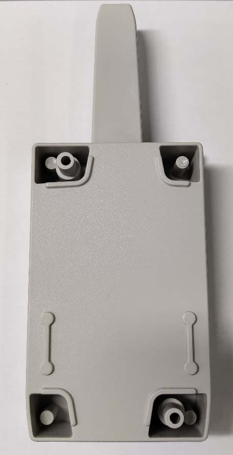
U5Z-CONNECT4CC
Apr 20, 2021CONNECT4 CC CONNECT CC-CAM CONNECT CC-ACT CONNECT CC-CIS
Equipment Class
CYY - Communications Receiver used w/Pt 15 Transmitter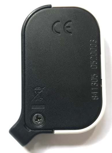
U5Z-GOMINI
Mar 14, 2021868 MHZ radio transmitter
Equipment Class
DSC - Part 15 Security/Remote Control Transmitter
U5Z-FREE15R
Apr 02, 2012RFID Reader
Equipment Class
DCD - Part 15 Low Power Transmitter Below 1705 kHz
U5Z-BASE5001B-2B
Dec 17, 2011Receiver for security gate system
Equipment Class
CYY - Communications Receiver used w/Pt 15 Transmitter