U5Z-FREE30RReader
JCM Technologies, S.A.U.
Click to zoom
Application Details
- Equipment Class
- DCD - Part 15 Low Power Transmitter Below 1705 kHz
- Date of Grant
- Oct 12, 2011
- Application Purpose
- Original Equipment
- Date of Application
- Oct 10, 2011
- Equipment Note
- Reader
- Frequency Range
- 0.12500000 - 0.12500000
- Company
- JCM Technologies, S.A.U.
- Country
- Spain
Documents & Files
Document Text
Text extracted from the exhibit documents filed with the FCC. Open a document above to read the original.
Users Manual
COD. 1247030-GB / 1.3 FREE 15 R / FREE 30 R 1 Hands free activator. TECHNICAL CHARACTERISTICS FREE 15 R FREE 30 R Operating frequency 125kHz Electricity 12/24V(ac)/(dc) +/- 10% Consumption 50mA Radiated power <25mW Wiring 4 wires Op. temperature -20ºC - +55ºC Airtightness IP66 Size 87 x 78 x 15,5 mm 205 x 183 x 14 mm Enabling area (hands-free mode) 1.5m 3m INSTALLATION (figure A) The activator is formed by two parts: a compact box (1) with a plastic front part and the wiring outlet at the back and an adhesive trim (2). It is designed to be fitted directly to or built into the wall. It is secured by two screws (3), separated by 60mm (ideal separation if it is built-into a standard plug or socket box). The adhesive is fitted over Position 2 in the Figure, ensuring that the led (5) is visible through the adhesive window. Before fitting the adhesive, screw in and configure the activator. N.B.: The activator should not be installed on metal surfaces, as this may reduce the enabling area. COD. 1247030-GB / 1.3 FREE 15 R / FREE 30 R 2 CONNECTION Connection is made through the wiring from the rear, which is connected directly to the auxiliary power supply. Signal Cable colour + (12V) Red - (GND) Black Sync IN Green Sync OUT White Wiring diagram for the installation of an activator: Where one activator only is to be used, the IN and OUT synch. signals must be short circuited. Wiring diagram for the installation of more than one activator in series (maximum 4) and avoiding interference between them. To do so, the OUT synch. signal must be connected to the IN synch. signal of the following activator. COD. 1247030-GB / 1.3 FREE 15 R / FREE 30 R 3 CONFIGURATION OF CHANNELS AND GROUPS Use the button (4) to configure the activator’s operating mode. Channel configuration: Keep the configuration button pressed down until the number of long red signals is equal to the channel to be configured. For example, if you want to configure channel 2, release the button after the second long red signal. Group configuration: Press the configuration button and keep it pressed down. The led will issue the red channel configuration signals followed by a series of flashing green signals to indicate that the open group will start the group selection sequence (long green signals indicating groups 1 to 7). Release the button at the required group. For example, if you want to configure group 5, release the button after the fifth long green signal. The procedure can be carried out as many times as required. Channel: This allows for the channel to be sent to the receiver to be selected. Group: This allows for the installation of more independently enabled doors (to a total of 22). COD. 1247030-GB / 1.3 FREE 15 R / FREE 30 R 4 OPERATING When the equipment is switched on, the LED will make as many red flashes as the channel you have configured and so many green flashes as the group has set. Then the LED will be green fixed. By bringing the tag/transmitter close to the hands-free activator or pressing the button, the activator will send a signal to the receiver in which it is programmed. USE OF THE EQUIPMENT This equipment is designed for be used in the access control for automatic doors. It is not guaranteed for other uses. The manufacturer reserves the right to modify equipment specifications without prior notice. WARNING Some structural elements of a building can affect the propagation of the signal that activates the tag. This can lead to accidental activation of the tag when the unit is at a distance greater than 3m from the activator. If this happens move the tag or the activator of his current location. JCM TECHNOLOGIES, S.A. declares that the product FREE 15 R is compliant with the requirements of the 1999/5/EEC Radio Equipment and Telecommunication Terminal Equipment Directive, provided it is used as established. This device complies with Part 15 of the FCC Rules. Operation is subject to the following two conditions: (1) this device may not cause harmful interference, and (2) this device must accept any interference received, including interference that may cause undesired operation. The users manual or instruction manual for an intentional or unintentional radiator shall caution the user that changes or modifications not expressly approved by the party responsible for compliance could void the user's authority to operate the equipment. CE DECLARATION OF CONFORMITY See website: www.jcm-tech.com
ID Label/Location Info
REVISAT MODIFICAT INFORMACIÓ CONFIDENCIAL G.Reverter 07-09-11 FREE 30R - location of FCC ID number 1:1 1 1 FCC ID: U5Z-FREE30R This device complies with Part 15 of the FCC Rules. Operation is subject to the following two conditions: (1) this device may not cause harmful interference, and (2) this device must accept any interference received, including interference that may cause undesired operation. Location FCC ID label (laser marking) 35x15mm 1.0 U5Z-FREE30R
Test Report
FCC CFR47 PART 15 SUBPART C CERTIFICATION TEST REPORT FOR RFID READER MODEL NUMBER: FREE30R REPORT NUMBER: 1001408287 FCC ID: U5Z-FREE30R ISSUE DATE: 2011-09-06 Prepared for JCM TECHNOLOGIES S A BISBE MORGADES, 46 BAIXOS VIC 08500, SPAIN Prepared by UNDERWRITERS LABORATORIES INC. 1285 WALT WHITMAN RD. MELVILLE, NY 11747, U.S.A. TEL: (631) 271-6200 FAX: (877) 854-3577 REPORT NO: 1001408287 DATE: 2011-09-06 FCC ID: U5Z-FREE30R Page 2 of 30 UNDERWRITERS LABORATORIES INC. FORM NO: CCSUP4701D 1285 WALT WHITMAN RD, MELVILLE, NY 11747, USA TEL: (631) 271-6200 FAX: (877) 854-3577 This report shall not be reproduced except in full, without the written approval of Underwriters Laboratories Inc. Revision History Rev. Issue Date Revisions Revised By -- 2011- 09-06 Initial Issue B. DeLisi -- 2011- 09-08 Updated Model number to Free30R. B. DeLisi REPORT NO: 1001408287 DATE: 2011-09-06 FCC ID: U5Z-FREE30R Page 3 of 30 UNDERWRITERS LABORATORIES INC. FORM NO: CCSUP4701D 1285 WALT WHITMAN RD, MELVILLE, NY 11747, USA TEL: (631) 271-6200 FAX: (877) 854-3577 This report shall not be reproduced except in full, without the written approval of Underwriters Laboratories Inc. TABLE OF CONTENTS 1. ATTESTATION OF TEST RESULTS ................................................................................. 4 2. TEST METHODOLOGY ..................................................................................................... 5 3. FACILITIES AND ACCREDITATION ................................................................................. 5 4. CALIBRATION AND UNCERTAINTY ................................................................................ 5 4.1. MEASURING INSTRUMENT CALIBRATION .............................................................. 5 4.2. SAMPLE CALCULATION ............................................................................................ 5 4.3. MEASUREMENT UNCERTAINTY ............................................................................... 5 5. EQUIPMENT UNDER TEST ............................................................................................... 6 5.1. DESCRIPTION OF EUT .............................................................................................. 6 5.2. DESCRIPTION OF AVAILABLE ANTENNAS .............................................................. 6 5.3. SOFTWARE AND FIRMWARE .................................................................................... 6 5.4. WORST-CASE CONFIGURATION AND MODE .......................................................... 6 5.5. MODIFICATIONS ........................................................................................................ 6 5.6. DESCRIPTION OF TEST SETUP ................................................................................ 7 6. TEST AND MEASUREMENT EQUIPMENT ....................................................................... 9 7. RADIATED EMISSION TEST RESULTS...........................................................................11 7.1. LIMITS AND PROCEDURE ........................................................................................11 7.2. TX SPURIOUS EMISSIONS 0.15 TO 30 MHz ............................................................12 7.3. TX SPURIOUS EMISSION 30 TO 1000 MHz .............................................................16 8. AC MAINS LINE CONDUCTED EMISSIONS ....................................................................18 9. SETUP PHOTOS ...............................................................................................................25 REPORT NO: 1001408287 DATE: 2011-09-06 FCC ID: U5Z-FREE30R Page 4 of 30 UNDERWRITERS LABORATORIES INC. FORM NO: CCSUP4701D 1285 WALT WHITMAN RD, MELVILLE, NY 11747, USA TEL: (631) 271-6200 FAX: (877) 854-3577 This report shall not be reproduced except in full, without the written approval of Underwriters Laboratories Inc. 1. ATTESTATION OF TEST RESULTS COMPANY NAME: JCM TECHNOLOGIES S A BISBE MORGADES, 46 BAIXOS VIC 08500, SPAIN EUT DESCRIPTION: RFID Reader MODEL: FREE30R SERIAL NUMBER: Non-serialized production unit DATE TESTED: 2011-08-22 to 2011-08-26 APPLICABLE STANDARDS STANDARD TEST RESULTS FCC PART 15 SUBPART C Pass Underwriters Laboratories Inc. tested the above equipment in accordance with the requirements set forth in the above standards, using test results reported in the test report documents referenced below and/or documentation furnished by the applicant. All indications of Pass/Fail in this report are opinions expressed by Underwriters Laboratories Inc. based on interpretations of these calculations. The results show that the equipment is capable of demonstrating compliance with the requirements as documented in this report. Note: The results documented in this report apply only to the tested sample, under the conditions and modes of operation, as described by the referenced documents. This document may not be altered or revised in any way unless done so by Underwriters Laboratories Inc. and all revisions are duly noted in the revisions section. Any alteration of this document not carried out by Underwriters Laboratories Inc. will constitute fraud and shall nullify the document. This report must not be used by the client to claim product certification, approval, or endorsement by NVLAP, NIST, any agency of the Federal Government, or any agency of any government. Approved & Released For UL By: Tested By: Joseph Danisi Bob DeLisi Sr. Project Engineer Sr. Staff Engineer UL UL REPORT NO: 1001408287 DATE: 2011-09-06 FCC ID: U5Z-FREE30R Page 5 of 30 UNDERWRITERS LABORATORIES INC. FORM NO: CCSUP4701D 1285 WALT WHITMAN RD, MELVILLE, NY 11747, USA TEL: (631) 271-6200 FAX: (877) 854-3577 This report shall not be reproduced except in full, without the written approval of Underwriters Laboratories Inc. 2. TEST METHODOLOGY The tests documented in this report were performed in accordance with ANSI C63.4-2009, FCC CFR 47 Part 2, FCC CFR 47 Part 15. 3. FACILITIES AND ACCREDITATION The…
Text truncated - open the document above for the full version.
Test Setup Photos
1. SETUP PHOTOS RADIATED EMISSION BELOW 30 MHz RADIATED EMISSIONS BELOW 30MHz (FRONT) RADIATED EMISSIONS BELOW 30MHz (BACK) RADIATED EMISSION ABOVE 30 MHz RADIATED EMISSIONS ABOVE 30 MHz (FRONT) RADIATED EMISSIONS ABOVE 30 MHz (BACK) AC MAINS LINE CONDUCTED EMISSION LINE CONDUCTED EMISSION (FRONT) END OF REPORT LINE CONDUCTED EMISSION (BACK)
Contact Information
Applicant
Juan Capdevila(General Manager)
Test Firm
UL LLCRick Titus
Technical Specifications
| # | Rule Parts | Frequency Range | Power Output |
|---|---|---|---|
| 1 | 15C | 0.125 MHz - 0.125 MHz | - |
Other Applications from JCM Technologies, S.A.U.
U5Z-RB-TX20C
Jul 25, 2024Safety edge wireless system consisting in a transmitter
Equipment Class
DXX - Part 15 Low Power Communication Device Transmitter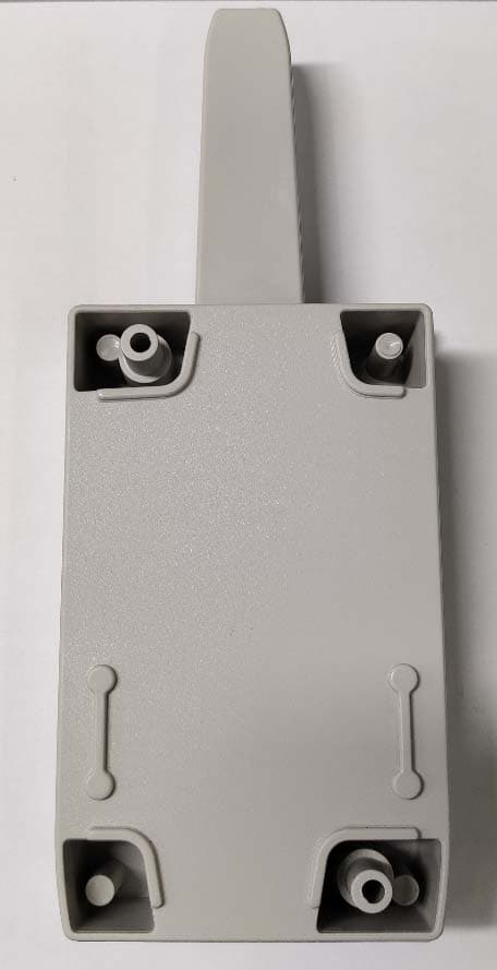
U5Z-CONNECT4CC
Apr 20, 2021CONNECT4 CC CONNECT CC-CAM CONNECT CC-ACT CONNECT CC-CIS
Equipment Class
CYY - Communications Receiver used w/Pt 15 Transmitter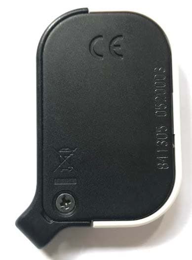
U5Z-GOMINI
Mar 14, 2021868 MHZ radio transmitter
Equipment Class
DSC - Part 15 Security/Remote Control Transmitter
U5Z-RB-P-RX10C
Apr 20, 2020Safety edge wireless receiver
Equipment Class
DSC - Part 15 Security/Remote Control Transmitter
U5Z-FREE15R
Apr 02, 2012RFID Reader
Equipment Class
DCD - Part 15 Low Power Transmitter Below 1705 kHz