U6BEF9RADAR DETECTOR
BG Tech America, Inc.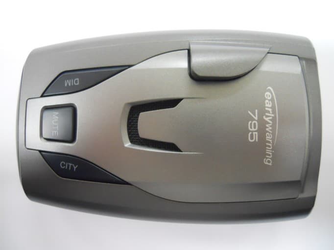
Click to zoom
Application Details
- Equipment Class
- CRD - Part 15 Radar Detector
- Date of Grant
- Jun 13, 2011
- Application Purpose
- Original Equipment
- Date of Application
- Jun 13, 2011
- Equipment Note
- RADAR DETECTOR
- Frequency Range
- 33400.00000000 - 36000.00000000
- Company
- BG Tech America, Inc.
- Country
- United States
Documents & Files
Document Text
Text extracted from the exhibit documents filed with the FCC. Open a document above to read the original.
External Photos
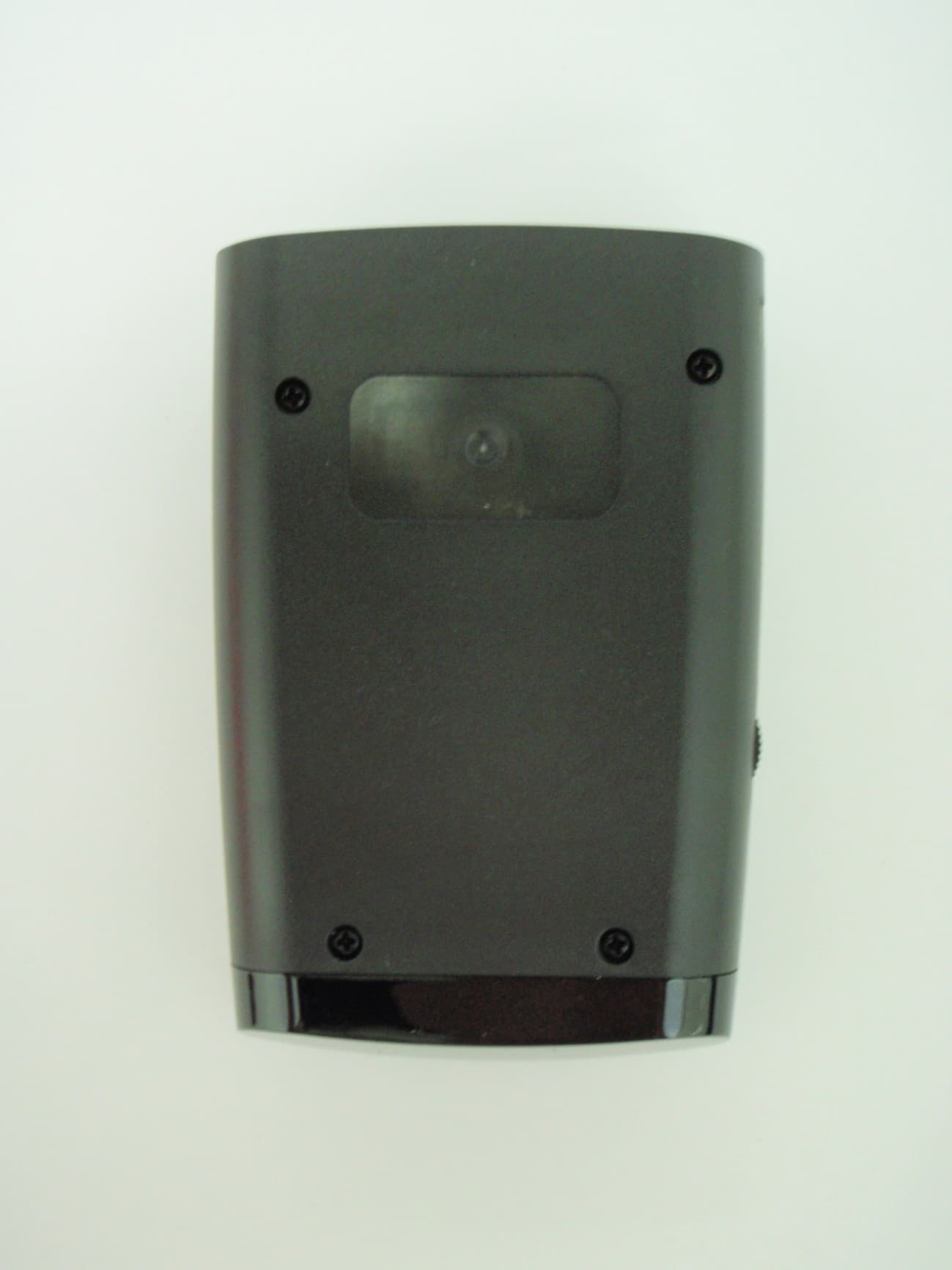
APPLICANT: BG TECH AMERICA INC. FCC ID: U6BEF9 EXTERNAL PHOTOS
Internal Photos
APPLICANT: BG TECH AMERICA INC. FCC ID: U6BEF9 INTERNAL PHOTOS
Test Report
FCC PART 15 RADAR DETECTOR REPORT Applicant BG TECH AMERICA, INC. Address 300 PARK BOULEVARD SUITE 335 ITASCA IL IL USA FCC ID: U6BEF9 Product Description RADAR DETECTOR Date Sample Received 5/4/2011 Date Tested 5/26/2011 Tested By Joe Scoglio Approved By Mario R. de Aranzeta Report Number 914UT11TestReport.doc Test Results PASS FAIL THE ATTACHED REPORT SHALL NOT BE REPRODUCED EXCEPT IN FULL WITHOUT THE WRITTEN APPROVAL OF TIMCO ENGINEERING, INC. 849 NW State Road 45 Newberry, Fl 32669 USA Phone: 888.472.2424 or 352.472.5500 Fax: 352.472.2030 Email: [email protected] Website: www.timcoengr.com Certificate # 0955-01 APPLICANT: BG TECH AMERICA, INC. FCC ID: U6BEF9 REPORT: B\BGTech_AMERICA\914UT11\914UT11TestReport.doc Page 2 of 12 TABLE OF CONTENTS GENERAL REMARKS ............................................................................................................. 3 GENERAL INFORMATION ...................................................................................................... 4 TEST EQUIPMENT LIST ......................................................................................................... 5 TEST PROCEDURES .............................................................................................................. 6 RADIATED SPURIOUS EMISSIONS ........................................................................................ 8 PEAK PLOT .......................................................................................................................... 10 AVERAGE PLOT ................................................................................................................... 11 RADIATED EMISSIONS TEST SETUP PHOTO ....................................................................... 12 APPLICANT: BG TECH AMERICA, INC. FCC ID: U6BEF9 REPORT: B\BGTech_AMERICA\914UT11\914UT11TestReport.doc Page 3 of 12 GENERAL REMARKS The attached report shall not be reproduced except in full without the written permission of Timco Engineering Inc. The test results relate only to the items tested. Summary The device under test does: fulfill the general approval requirements as identified in this test report not fulfill the general approval requirements as identified in this test report Attestations This equipment has been tested in accordance with the standards identified in this test report. To the best of my knowledge and belief, these tests were performed using the measurement procedures described in this report. All instrumentation and accessories used to test products for compliance to the indicated standards are calibrated regularly in accordance with ISO 17025 requirements. Certificate # 0955-01 I attest that the necessary measurements were made, under my supervision, at: Timco Engineering Inc. 849 NW State Road 45 Newberry, Fl 32669 Authorized Signatory Name: Mario de Aranzeta C.E.T. Compliance Engineer/ Lab. Supervisor Date: 6/13/11 APPLICANT: BG TECH AMERICA, INC. FCC ID: U6BEF9 REPORT: B\BGTech_AMERICA\914UT11\914UT11TestReport.doc Page 4 of 12 GENERAL INFORMATION The test results relate only to the items tested. DUT Description RADAR DETECTOR FCC ID U6BEF9 DUT Power Source 110–120Vac/50– 60Hz DC Power Battery Operated Exclusively Test Item Prototype Pre-Production Production Modifications to DUT None Test Standards FCC Part 15, Subpart B, ANSI C63.4-2003 APPLICANT: BG TECH AMERICA, INC. FCC ID: U6BEF9 REPORT: B\BGTech_AMERICA\914UT11\914UT11TestReport.doc Page 5 of 12 TEST EQUIPMENT LIST Device Manufacturer Model Serial Number Cal/Char Date Due Date 3-Meter Semi- Anechoic Chamber Panashield N/A N/A Listed 5/10/10 5/10/12 Antenna: Dipole Kit Electro- Metrics TDA-30/1-4 153 CHAR 7/10/09 7/10/11 Frequency Counter HP 5385A 2730A03025 CAL 8/4/09 8/4/11 Hygro- Thermometer Extech 445703 0602 CAL 1/30/10 1/30/12 Modulation Analyzer HP 8901A 3435A06868 CAL 6/26/09 6/26/11 Digital Multimeter Fluke FLUKE-77 35053830 CAL 11/18/09 11/18/11 Analyzer Tan Tower Preamplifier HP 8449B-H02 3008A00372 CAL 11/21/09 11/21/11 Analyzer Tan Tower Quasi- Peak Adapter HP 85650A 3303A01690 CAL 11/22/09 11/22/11 Analyzer Tan Tower RF Preselector HP 85685A 3221A01400 CAL 11/21/09 11/21/11 Analyzer Tan Tower Spectrum Analyzer HP 8566B Opt 462 3138A07786 3144A20661 CAL 11/24/09 11/24/11 Temperature Chamber Tenney Engineering TTRC 11717-7 CHAR 4/25/10 4/25/12 APPLICANT: BG TECH AMERICA, INC. FCC ID: U6BEF9 REPORT: B\BGTech_AMERICA\914UT11\914UT11TestReport.doc Page 6 of 12 TEST PROCEDURES General: This report shall NOT be reproduced except in full without the written approval of TIMCO ENGINEERING, INC. RADIATION INTERFERENCE: Testing was done in accordance with ANSI C63.4-2003. Section 15.35(b) specifies the use of an average detector in this band. In addition, the peak level of an emission shall not exceed the average limit by more than 20 dB using a minimum Resolution Bandwidth (RBW) of 1 MHz and minimum Video Bandwidth (VBW) OF 1 MHz. The following procedure is designed to determine if there are any spurious emissions from the local oscillator within the band of interest along with any additional spurious emissions caused by other circuitry within the device. 1) Determine the frequency of the peak emission: Start Frequency 11.7 GHz Stop Frequency 12.2 GHz RBW equal to or greater than 1 MHz VBW equal to or greater than 1 MHz Detector Function Peak Maximize the emissions with regards to device orientation, antenna polarization, and antenna height. Sweep the band using Max Hold for a minimum of 2 minutes. Record this frequency for measuring the peak emission. In addition record the frequency of other spurious emissions noted. 2) Determine the peak level of the emission: Center Frequency Set to the frequency determined in Step 1 RBW Equal to or greater than 1 MHz VBW Equal to or greater than 1 MHz Detector Function Peak Measure the value of the peak emission using Max Hold for a minimum of 2 minutes. This can be done at zero span or a frequency span where the analyzer does not s…
Text truncated - open the document above for the full version.
Contact Information
Applicant
Si Song(President)
Test Firm
Timco Engineering, Inc.Bruno Clavier
Technical Specifications
| # | Rule Parts | Frequency Range | Power Output |
|---|---|---|---|
| 3 | 15B | 33.40 GHz - 36.00 GHz | - |
Other Applications from BG Tech America, Inc.
U6BDH10
May 16, 2011RADAR DETECTOR
Equipment Class
CRD - Part 15 Radar Detector
U6BCG7
May 30, 2007Radar Detector
Equipment Class
CRD - Part 15 Radar Detector