U6OG0S02HP Prime Wireless Dongle
INVENTEC BESTA CO.,LTD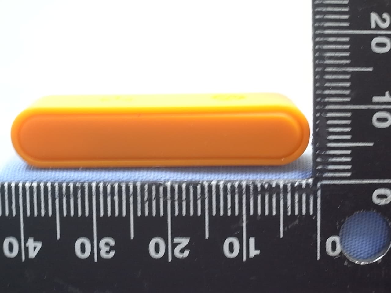
Click to zoom
Application Details
- Equipment Class
- DTS - Digital Transmission System
- Date of Grant
- Dec 21, 2013
- Application Purpose
- Original Equipment
- Date of Application
- Dec 15, 2013
- Equipment Note
- HP Prime Wireless Dongle
- Frequency Range
- 2402.00000000 - 2480.00000000
- Company
- INVENTEC BESTA CO.,LTD
- Country
- Taiwan
Documents & Files
Document Text
Text extracted from the exhibit documents filed with the FCC. Open a document above to read the original.
Users Manual
754967-B21 1 2 The information contained herein is subject to change without notice. The only warranties for HP products and services are set forth in the express warranty statements accompanying such products and services. Nothing herein should be construed as constituting an additional warranty. HP shall not be liable for technical or editorial errors or omissions contained herein. © Copyright 2013 Hewlett-Packard Development Company, L.P. First Edition: December 2013 Replace this box with PI statement as per spec. Replace this box with PI statement as per spec. Replace this box with PI statement as per spec. Replace this box with PI statement as per spec. 3 4 RMN FCC ID U6OG0S02 FCC ID U6OG0S03 IC: 9982A-G0S02 IC: 9982A-G0S03 CNC XXXXXXX CMIIT ID : xxxxyyzzzz CAN ICES-3 (B)/NMB-3(B) HP Connectivity Kit HP-Verbindungskit Kit de conectividad HP Kit de connexion HP Kit de Conectividade HP HP aansluitkit HP USB Connectivity Kit Emulator Quick Start Guide http://www.hp.com/calculators For regulatory and safety notices, refer to the CD included with your product. For regulatory and safety notices, refer to the CD included with your product. For regulatory and safety notices, refer to the CD included with your product. For regulatory and safety notices, refer to the CD included with your product. For regulatory and safety notices, refer to the CD included with your product. For regulatory and safety notices, refer to the CD included with your product. For regulatory and safety notices, refer to the CD included with your product. GR ES FR NL BR CN Translator: please rear- range in this order: EN, GR, ES, FR, NL, BR, CN Regulatory notices This document provides country- and region-specific non-wireless and wireless regulatory notices and compliance information for your product. Some of these notices may not apply to your product. 이 문서에는 국가 및 지역별 유무선 규제사항 설명과 제품의 준수 정보가 있습니다. 이러한 정보 중 일부는 귀하의 제품에 적용되지 않을 수 있습니다. Federal Communications Commission notice This equipment has been tested and found to comply with the limits for a Class B digital device, pursuant to Part 15 of the FCC Rules. These limits are designed to provide reasonable protection against harmful interference in a residential installation. This equipment generates, uses, and can radiate radio frequency energy and, if not installed and used in accordance with the instructions, may cause harmful interference to radio communications. However, there is no guarantee that interference will not occur in a particular installation. If this equipment does cause harmful interference to radio or television reception, which can be determined by turning the equipment off and on, the user is encouraged to try to correct the interference by one or more of the following measures: ■Reorient or relocate the receiving antenna. ■Increase the separation between the equipment and receiver. ■Connect the equipment to an outlet on a circuit different from that to which the receiver is connected. ■Consult the dealer or an experienced radio or television technician for help. Modifications The FCC requires the user to be notified that any changes or modifications made to this device that are not expressly approved by HP may void the user's authority to operate the equipment. Cables To maintain compliance with FCC Rules and Regulations, connections to this device must be made with shielded cables having metallic RFI/EMI connector hoods. Declaration of Conformity for products marked with the FCC logo (United States only) This device complies with Part 15 of the FCC Rules. Operation is subject to the following 2 conditions: 1.This device may not cause harmful interference. 2.This device must accept any interference received, including interference that may cause undesired operation. If you have questions about the product that are not related to this declaration, write to Hewlett-Packard Company P. O. Box 692000, Mail Stop 530113 Houston, TX 77269-2000 For questions regarding this FCC declaration, write to Hewlett-Packard Company P. O. Box 692000, Mail Stop 510101 Houston, TX 77269-2000 or call HP at 281-514-3333 To identify your product, refer to the part, series, or model number located on the product. Products with wireless LAN devices or HP Mobile Broadband Modules This device must not be co-located or operating in conjunction with any other antenna or transmitter. Å WARNING: Exposure to Radio Frequency Radiation The radiated output power of this device is below the FCC/Industry Canada radio frequency exposure limits. Nevertheless, the device should be used in such a manner that the potential for human contact is minimized during normal operation of tablet PCs and notebook computers. During normal operation of tablet PCs and notebook computers with displays equal to or less than30.5 cm (12 inches): To avoid the possibility of exceeding the FCC/Industry Canada radio frequency exposure limits, human proximity to the antennas should not be less than 2.5 cm (1 inch). To identify the location of the wireless antennas, refer to the computer user guides included with your computer. During normal operation of notebook computers with displays greater than 30.5 cm (12 inches): To avoid the possibility of exceeding the FCC/Industry Canada radio frequency exposure limits, human proximity to the antennas should not be less than 20 cm (8 inches), including when the computer display is closed. To identify the location of the wireless antennas, refer to the computer user guides included with your computer. Ä CAUTION: When using IEEE 802.11a wireless LAN, this product is restricted to indoor use, due to its operation in the 5.15- to 5.25-GHz frequency range. FCC/Industry Canada requires this product to be used indoors for the frequency range of 5.15 GHz to 5.25 GHz to reduce the potential for harmful interference to co-channel mobile satellite systems. High-power radar is allocated as the primary user of the 5.25- to 5.35-GHz and 5.65- to 5.85-GHz bands. These radar stations c…
Text truncated - open the document above for the full version.
External Photos
INVENTEC BESTA CO., LTD. HP Prime Wireless Dongle FCC ID. : U6OG0S02 IC: 9982A-G0S02 EUT External Photos Figure 1 HP Prime Wireless Dongle (Front View) Figure 2 HP Prime Wireless Dongle (Back View) INVENTEC BESTA CO., LTD. HP Prime Wireless Dongle FCC ID. : U6OG0S02 IC: 9982A-G0S02 Figure 3 HP Prime Wireless Dongle (Side View) Figure 4 HP Prime Wireless Dongle (Side View) INVENTEC BESTA CO., LTD. HP Prime Wireless Dongle FCC ID. : U6OG0S02 IC: 9982A-G0S02 Figure 5 HP Prime Wireless Dongle (Top View) Figure 6 HP Prime Wireless Dongle (Bottom View)
ID Label/Location Info
INVENTEC BESTA CO., LTD. HP Prime Wireless Dongle FCC ID. : U6OG0S02 IC: 9982A-G0S02 FCC ID & IC Label Location z Label Placement Location z FCC ID & IC Label Format FCC ID & IC Label Placement Location INVENTEC BESTA CO., LTD. HP Prime Wireless Dongle FCC ID. : U6OG0S02 IC: 9982A-G0S02 z FCC ID & IC Label Format FCC ID & IC Label Placement Location
Internal Photos
INVENTEC BESTA CO., LTD. HP Prime Wireless Dongle FCC ID. : U6OG0S02 IC: 9982A-G0S02 EUT Internal Photos Figure 7 HP Prime Wireless Dongle (Removed Covers) Figure 8 HP Prime Wireless Dongle (Main Board, Front View) INVENTEC BESTA CO., LTD. HP Prime Wireless Dongle FCC ID. : U6OG0S02 IC: 9982A-G0S02 Figure 9 HP Prime Wireless Dongle (Main Board, Back View)
RF Exposure Info
Maximum Permissive Exposure FCC ID: U6OG0S02 IC: 9982A-G0S02 Product Name: HP Prime Wireless Dongle Model No: G0S02-60001 EUT Side: EUT Lie: [Maximum measured transmitter power] The max output power E.I.R.P=-11.76dBm=0.0667mW Per KDB 447498 clarifies "When the minimum test separation distance is < 5 mm, a distance of 5 mm is applied to determine SAR test exclusion.", this device has output power 0.00064mW < threshold 10 mW thus this device is exempt from SAR test. Sincerely Yours, ____________________________________ Mr. Ben Cheng Manager AUDIX Technology Corporation
Test Report
FCC ID: U6OG0S02 IC:9982A-G0S02 Page 1 of 49 AUDIX Technology Corporation Report No. EM-F1020858 APPLICATION FOR CERTIFICATION On Behalf of INVENTEC BESTA CO., LTD. HP Prime Wireless Dongle Model No. : G0S02-60001 FCC ID : U6OG0S02 IC: 9982A-G0S02 Brand : hp Prepared for : INVENTEC BESTA CO., LTD. 10FL., No.36, Lane 513, Rui Guang Road, Nei Hu Dist., Taipei 114, Taiwan Prepared by : AUDIX Technology Corporation EMC Department No. 53-11, Dingfu, Linkou Dist., New Taipei City 244, Taiwan, R.O.C. Tel : (02) 2609-9301, 2609-2133 Fax: (02) 2609-9303 File Number C1M1311177 Report Number EM-F1020858 Date of Test Dec. 02 ~ 06, 2013 Date of Report Dec. 06, 2013 FCC ID: U6OG0S02 IC:9982A-G0S02 Page 2 of 49 AUDIX Technology Corporation Report No. EM-F1020858 TABLE OF CONTENTS Description Page TEST REPORT CERTIFICATION ................................................................................................ 4 1. DESCRIPTION OF REVISION HISTORY .......................................................................... 5 2. GENERAL INFORMATION .................................................................................................. 6 2.1. Description of Device (EUT) ........................................................................................................... 6 2.2. Tested Supporting System Details ................................................................................................... 7 2.3. Description of Test Facility ............................................................................................................. 7 2.4. Measurement Uncertainty ................................................................................................................ 8 3. CONDUCTED EMISSION MEASUREMET ........................................................................ 9 3.1. Test Equipment ................................................................................................................................ 9 3.2. Block Diagram of Test Setup........................................................................................................... 9 3.3. Powerline Conducted Emission Limit §15.207, Class B, RSS-Gen §7.2.2/Table 2] ................... 9 3.4. Operating Condition of EUT ......................................................................................................... 10 3.5. Test Procedure ............................................................................................................................... 10 3.6. Conducted Emission Measurement Results ................................................................................... 10 4. RADIATED EMISSION MEASUREMENT ....................................................................... 13 4.1. Test Equipment .............................................................................................................................. 13 4.2. Test Setup ...................................................................................................................................... 13 4.3. Radiated Emission Limits (§15.209, RSS-210 §2.7/Table 2) ........................................................ 15 4.4. Operating Condition of EUT ......................................................................................................... 15 4.5. Test Procedure ............................................................................................................................... 16 4.6. Test Results .................................................................................................................................... 17 5. 6dB BANDWIDTH MEASUREMENT ................................................................................ 25 5.1. Test Equipment .............................................................................................................................. 25 5.2. Block Diagram of Test Setup......................................................................................................... 25 5.3. Specification Limits [§15.247(a)(2), RSS-210 §A8.2 (a)] ............................................................ 25 5.4. Operating Condition of EUT ......................................................................................................... 25 5.5. Test Procedure ............................................................................................................................... 25 5.6. Test Results .................................................................................................................................... 26 6. MAXIMUM PEAK OUTPUT POWER MEASUREMENT .............................................. 29 6.1. Test Equipment .............................................................................................................................. 29 6.2. Block Diagram of Test Setup......................................................................................................... 29 6.3. Specification Limits (§15.247(b)-(3)) ............................................................................................ 29 6.4. Operating Condition of EUT ......................................................................................................... 29 6.5. Test Procedure ............................................................................................................................... 29 6.6. Test Results .................................................................................................................................... 30 7. EMISSION LIMITATIONS MEASUREMENT ................................................................. 31 7.1. Test Equipment .............................................................................................................................. 31 7.2. Block Diagram of Test Setup......................................................................................................... 31 7.3. Specification Limits (…
Text truncated - open the document above for the full version.
Test Setup Photos
FCC ID: U6OG0S02 IC:9982A-G0S02 Page 47 of 49 AUDIX Technology Corporation Report No. EM-F1020858 11. PHOTOGRAPHS 11.1. Photos of Conducted Disturbance Measurement FRONT VIEW OF CONDUCTED MEASUREMENT BACK VIEW OF CONDUCTED MEASUREMENT FCC ID: U6OG0S02 IC:9982A-G0S02 Page 48 of 49 AUDIX Technology Corporation Report No. EM-F1020858 11.2. Photos of Radiated Measurement at Semi-Anechoic Chamber 11.2.1. Frequency Below 1GHz 11.2.2. Frequency Above 1GHz FCC ID: U6OG0S02 IC:9982A-G0S02 Page 49 of 49 AUDIX Technology Corporation Report No. EM-F1020858 11.3. Photo of Section RF Conducted Measurement
Contact Information
Applicant
Yuan Young Chang
Technical Contact
Audix Technology CorporationBen Cheng
[email protected]886-2-26099301
No.53-11,Digful, Linkou District · New Taipei City · Taiwan
Test Firm
Audix Technology CorporationJeff Chen
Technical Specifications
| # | Rule Parts | Frequency Range | Power Output |
|---|---|---|---|
| 1 | 15C | 2.40 GHz - 2.48 GHz | 70.00 µW |
Other Applications from INVENTEC BESTA CO.,LTD
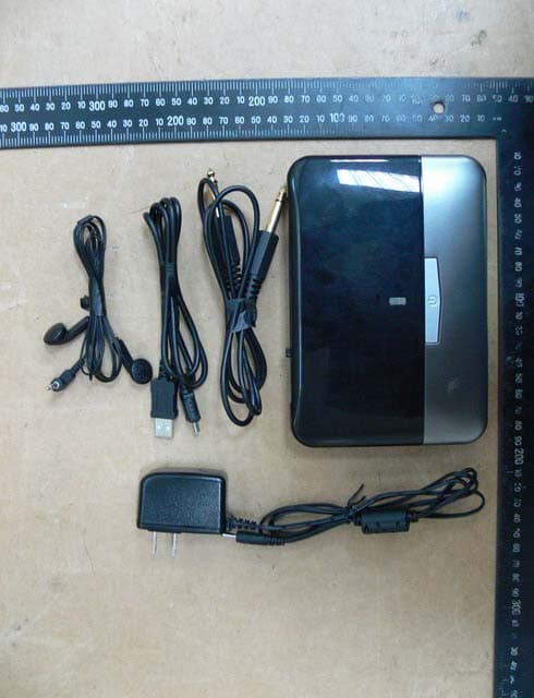
U6OCA913
Dec 01, 2014Digital Wireless Receiver
Equipment Class
DTS - Digital Transmission System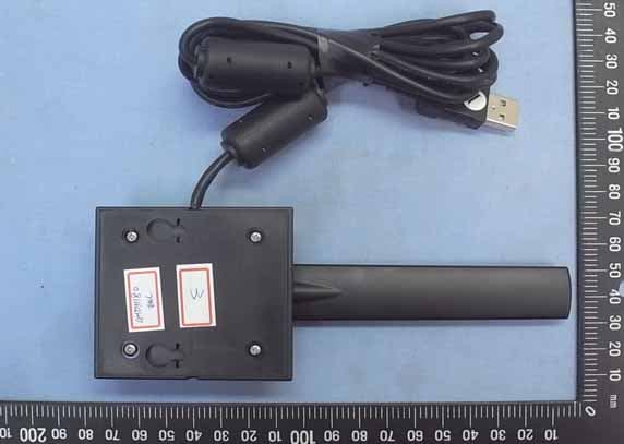
U6OG0S03
Dec 19, 2013HP Prime Wireless Antenna
Equipment Class
DTS - Digital Transmission System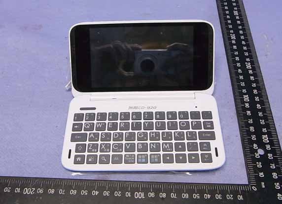
U6OCA012
Jul 18, 2013Electronic Dictionary
Equipment Class
DTS - Digital Transmission System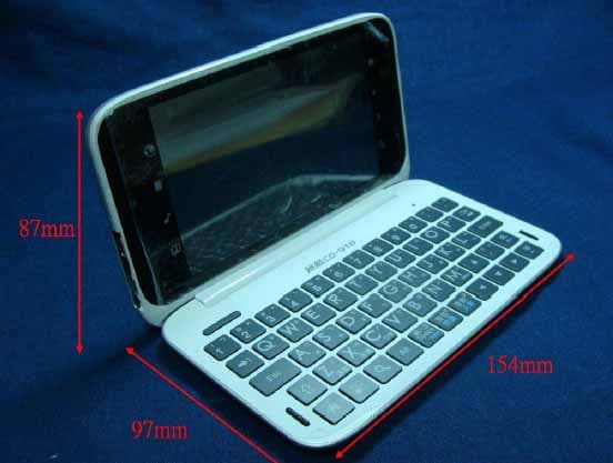
U6OCA017
Jan 15, 2012Electronic Dictionary
Equipment Class
DTS - Digital Transmission System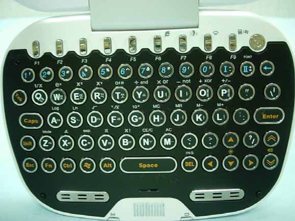
U6OKA015Z1
Aug 07, 2007Electronic Dictionary
Equipment Class
DTS - Digital Transmission System