U6YRD-FA3221Premium Seat Electronics Box
Panasonic Avionics Corporation
Click to zoom
Application Details
- Equipment Class
- DTS - Digital Transmission System
- Date of Grant
- Jun 04, 2007
- Application Purpose
- Original Equipment
- Date of Application
- May 20, 2007
- Equipment Note
- Premium Seat Electronics Box
- Frequency Range
- 2412.00000000 - 2462.00000000
- Country
- United States
Documents & Files
Document Text
Text extracted from the exhibit documents filed with the FCC. Open a document above to read the original.
Users Manual
Users Guide and Regulatory Statement RS-FA3221-01 Premium Seat Electronics Box Revision NEW Panasonic Avionics Corporation Page 2 of 7 USERS GUIDE AND REGULATORY STATEMENT for the PREMIUM SEAT ELECTRONICS BOX Part Number: RD-FA3221-01 September 21, 2007 Prepared by: PANASONIC AVIONICS CORPORATION 26200 Enterprise Way Lake Forest, CA 92630 USA Users Guide and Regulatory Statement RS-FA3221-01 Premium Seat Electronics Box Revision NEW Panasonic Avionics Corporation Page 3 of 7 REVISION HISTORY REV DATE REASON FOR REVISION NEW September 21, 2007 Initial Release Users Guide and Regulatory Statement RS-FA3221-01 Premium Seat Electronics Box Revision NEW Panasonic Avionics Corporation Page 4 of 7 TABLE OF CONTENTS 1.0 INTRODUCTION ................................................................................................................................... 5 1.1 Purpose ............................................................................................................................................. 5 1.2 Reference Documents....................................................................................................................... 5 1.3 Acronyms and Abbreviations............................................................................................................. 5 2.0 EQUIPMENT/SYSTEM DESCRIPTION ................................................................................................ 6 2.1 IFE Environment................................................................................................................................ 6 2.2 PSEB ................................................................................................................................................. 6 3.0 REGULATORY INFORMATION ........................................................................................................... 7 3.1 FCC Statement.................................................................................................................................. 7 3.2 SAR Compliance Statement.............................................................................................................. 7 3.3 Industry Canada ................................................................................................................................ 7 3.4 Europe – R&TTE Directive 99/5/EC, Wireless Notice....................................................................... 7 LIST OF FIGURES Figure 1. PSEB Outline Drawing (P/N RD-FA3221-01) ............................................................................... 6 Users Guide and Regulatory Statement RS-FA3221-01 Premium Seat Electronics Box Revision NEW Panasonic Avionics Corporation Page 5 of 7 1.0 INTRODUCTION 1.1 Purpose This User’s Guide addresses the specific regulations regarding the use of the Premium Seat Electronic Box (PSEB). 1.2 Reference Documents 44-26-72 Premium Seat Electronics Box Component Maintenance Manual 1.3 Acronyms and Abbreviations AOD Audio On Demand CAGE Commercial and Government Entity CD Compact Disc EIRP Equivalent Isotropic Radiated Power FCC Federal Communications Commission GHz Gigahertz IFES In-Flight Entertainment System MHz Megahertz MPEG Moving Picture Experts Group PED Passenger Entertainment Device` PSEB Premium Seat Electronics Box SAR Specific Absorption Rate SM Smart Monitor VOD Video On Demand WLAN Wireless Local Area Network Users Guide and Regulatory Statement RS-FA3221-01 Premium Seat Electronics Box Revision NEW Panasonic Avionics Corporation Page 6 of 7 2.0 EQUIPMENT/SYSTEM DESCRIPTION 2.1 IFE Environment eX2 is an electronic control data and audio/video distribution system providing digital Video on Demand (VOD) and Audio on Demand (AOD) to the passenger seat. The system architecture is modular in design. eX2 uses Moving Picture Experts Group (MPEG) encoding techniques for audio/video data compression providing high-resolution digital video and compact disc (CD) quality audio to the seats without using excessive system bandwidth. eX2 uses dual fibre-channel links to provide high speed 2.125 Gbps MPEG video/audio data transfer between head-end equipment. eX2 also provides broadband Ethernet network connectivity between the passenger-computing device at the seat and the head-end network equipment. The system is used for Internet data application and streaming digital video/audio content distribution. eX2 provides a family of devices that allows the passenger to interact with the system. Alternatively, a passenger may have a compatible Passenger Electronic Device (PED), which can be used to display and interact with the eX2 network to offer web browsing, e-mail, e-commerce, or viewing of a short entertainment program. 2.2 PSEB The Premium Seat Electronic Box (PSEB) is a component of the eX2 In-flight Entertainment System (IFES) developed by Panasonic Avionics Corporation. The PSEB is mounted under the passenger seat in any orientation. The PSEB is designed to provide video entertainment and peripheral interfaces for one premium class seat. The PSEB drawing is shown in Figure 1. Figure 1. PSEB (P/N RD-FA3221-01) Users Guide and Regulatory Statement RS-FA3221-01 Premium Seat Electronics Box Revision NEW Panasonic Avionics Corporation Page 7 of 7 3.0 REGULATORY INFORMATION This product has been tested and complies with the specifications for a digital device pursuant to Federal Communications Commission (FCC) specification IEEE 802.11. 3.1 FCC Statement The Premium Seat Electronics Box (PSEB) contains a radio transmitter, intentional radiator, and complies with the specifications for a Class B digital device in accordance with FCC Part 15 Rules. Modifications to the PSEB not authorized by Panasonic Avionics Corporation may void the certification of this equipment and void the user’s authority to use this equipment. 3.2 SAR Compliance Statement This equipment is compliant with Specific Absorption Rate (SAR) limits specified for General Population/Uncon…
Text truncated - open the document above for the full version.
Cover Letter(s)
May 2, 2007 American TCB 6731 Whittier Ave., Suite C110 McLean, VA 22101 Gentlemen: The attached documentation is provided in support of a formal submission to your organization for an approval of an intentional unlicensed transmitter. On behalf of our client, Aegis Labs has included an application for a Grant of Equipment Authorization pursuant to Subpart C of part 15 of FCC Rules (47 CFR) regarding intentional radiators. The data within the test report demonstrates the equipment was tested in a manner described under Part 2 and 15 of the Code of Federal Regulations. This is an approval of the Premium Seat Electronics Box (MN: RD-FA3221-01, FCC ID: U6YRD- FA3221). The PSEB is a device designed to provide video entertainment and peripheral interfaces for one seat in the premium class of an aircraft. It will be installed below the passenger seat. An 802.11abg radio module (Intel PRO/Wireless 2915ABG) will be integrated in the chassis of the PSEB and the transmitter/receiving antenna will be remotely located off to the left or right of the passenger depending on the location of the seat (using a 52 inch long coax cable) in the vicinity between the foot and knee of a passenger. The coax will connect to the radio module using an SMA Type connector but will not be readily accessible to the passenger. It was tested with a Centurion Antennas (MN: WID2452) continuously transmitting and receiving form the Main antenna port. If there are any additional questions or if further information is needed, please contact us at your earliest convenience. Sincerely, Johnny Candelas Aegis Labs, Inc. Test Technician Enclosure (1 Emissions Test Report + Exhibits)
Cover Letter(s)
American Telecommunications Certification Body Inc. 6731 Whittier Ave, McLean, VA 22101 October 2, 2007 TO: FCC FROM: American TCB RE: FCC ID: U6YRD-FA3221 request for supercede of information. Please replace “original manuals 1 through 4 uploaded on 5/21/07 with new manual uploaded 9/28/07. The reason for the action is that the original manuals contained confidential information – the new manuals do not. Also, please replace confidentiality letter request originally uploaded 5/21/07 with the one uploaded 10/2/07. We had the item mentioning design drawing removed. It did not apply. Last, please replace first supercede request letter with this one. Thank you Marianne Bosley American TCB Inc. Direct – 717-676-3203
External Photos
PSEB Top View PSEB Bottom View Antenna Top View Antenna Bottom View
ID Label/Location Info
Label Thi s devi ce com pl i es wi th par t 15 of the FC C r ul es . Oper ati on i s subj ect to the fol l ow i ng two condi ti ons: 1 -Thi s devi ce m ay not cause har m ful i nter fer ence . 2- This device must accept any interference received , i ncl udi ng i nter fer ence that m ay cause undesi r ed oper ati on . FCC ID: U6 YRD-FA3221 Panasonic A vionics Corporat ion Par t Num ber : R D-FA3221 - 01 IC ID: 216 P -RDFA3221 PSEB Top View
Internal Photos
Top View “Cover Removed” Top View “Unit Opened” Far View “Board Installed” Close Up View “Board Installed” Close Up View “Board Uninstalled” Antenna “Top Removed” Antenna “Bottom Removed”
RF Exposure Info
Specifications subject to change without notice. 3425 N.44 th Street, LINCOLN, NE 68504 USA SALES PHONE: 800.228.4563 PHONE: 402.467.4491 • FAX: 402.467.4528 www.centurion.com • [email protected] Copyright © 2005 Centurion Wireless Technologies, Inc. All Rights Reserved Specifications: Tape and reel packaging for high volume pick-and-place manufacturing processes Planar Inverted F Antenna (PIFA) requires ground plane to radiate efficiently Conformance to European RoHS Directive 2002/95/EC Frequency Ranges 2.4 - 2.5 GHz 5.15 - 5.875 GHz Gain >3 dBi >4 dBi Polarization Linear Impedance 50 ohms VSWR <2.5:1 Dimensions (L x W x H) 16 x 16 x 6 mm Weight 2 g Carrier Material Black color resin Connectors: Model # Part # Description Connector WID2452 CAF94400 Tape and Reel N/A WID2452-SM CAF94377 Eval PCBA SMA-female Panel D-Puck a – 12/28/05 D-Puck Model Number: WID2452 Internal Antenna – Surface Mount Back Azimuth: Total Gain Elevation: Total Gain VSWR 1. Feed pad. Provide 50-ohm signal to pad. Isolate feed pad from ground as required to provide 50-ohm signal at top mounting surface. Matching network components (Pi or L type) will be required on the input feed line. 2. Ground pad.
RF Exposure Info
PSEB Antenna Detail PSEB Antenna PSEB with Intel WM3B2915ABG SMA Connector RG 316 , 52 Inches Long PSEB Antenna Typical PSEB / PSEB Antenna Installation Antenna - Centurion CAF94400 Plastic Cover PWB - Ground Plane Metal base SMA Connector Approximate Size (Inches) 3.6 L x 2.2 D x 1.0 H Panasonic Avionics PSEB Antenna WHW 01-10-07
RF Exposure Info
© 2007 RF Exposure Lab, LLC This report shall not be reproduced except in full without the written approval of RF Exposure Lab, LLC. 2867 Progress Place, Suite 4D • Escondido, CA 92029 • U.S.A. TEL (760) 737-3131 • FAX (760) 737-9131 http://www.rfexposurelab.com CERTIFICATE OF COMPLIANCE SAR EVALUATION Panasonic Dates of Test: April 16, 2007 26200 Enterprise Way Test Report Number: SAR.20070401 Lake Forest, CA 92630 This wireless mobile and/or portable device has been shown to be compliant for localized specific absorption rate (SAR) for uncontrolled environment/general exposure limits specified in ANSI/IEEE Std. C95.1-1999 and had been tested in accordance with the measurement procedures specified in IEEE 1528-2003, OET Bulletin 65 Supp. C, RSS-102 and Safety Code 6 (See test report). I attest to the accuracy of the data. All measurements were performed by myself or were made under my supervision and are correct to the best of my knowledge and belief. I assume full responsibility for the completeness of these measurements and vouch for the qualifications of all persons taking them. RF Exposure Lab, LLC certifies that no party to this application has been denied FCC benefits pursuant to Section 5301 of the Anti-Drug Abuse Act of 1988, 21 U.S.C. 853(a). Jay M. Moulton Vice President Certificate # 2387.01 FCC ID: U6YRD-FA3221 IC Certificate: 216P-RDFA3221 Model(s): RD-FA3221-01 Test Sample: Pre-Production Unit same as Production Serial No.: D085560 Equipment Type: Wireless Controller for Airplane Seat Classification: Portable Transmitter Next to Body TX Frequency Range: 2412 – 2462 MHz, 5150 – 5250 MHz Frequency Tolerance: ± 25 ppm Maximum RF Output: 2450 MHz – 16.9 dBm, 5.15-5.25 GHz – 12.1 dBm Conducted Signal Modulation: DSSS, OFDM Antenna Type (Length): External(P/N RD-FA8808-01) Battery: Hardwired to Airplane Power Application Type: Certification FCC Rule Parts: Part 15C & 15E Industry Canada:RSS-102 FCC ID: U6YRD-FA3221 © 2007 RF Exposure Lab, LLC Page 2 of 112 This report shall not be reproduced except in full without the written approval of RF Exposure Lab, LLC. Table of Contents 1. Introduction ...........................................................................................................................3 SAR Definition [5]......................................................................................................................3 2. SAR Measurement Setup .....................................................................................................4 Robotic System .........................................................................................................................4 System Hardware .....................................................................................................................4 System Description ...................................................................................................................4 E-Field Probe ............................................................................................................................5 3. Robot Specifications .............................................................................................................7 4. Probe and Dipole Calibration ................................................................................................8 5. Phantom & Simulating Tissue Specifications........................................................................9 SAM Phantom ...........................................................................................................................9 Brain & Muscle Simulating Mixture Characterization ................................................................9 Device Holder ...........................................................................................................................9 6. Definition of Reference Points.............................................................................................10 Ear Reference Point................................................................................................................10 Device Reference Points ........................................................................................................10 7. Test Configuration Positions ...............................................................................................11 Positioning for Cheek/Touch [5] ..............................................................................................11 Positioning for Ear / 15 ̊ Tilt [5]................................................................................................12 Body Worn Configurations ......................................................................................................13 8. ANSI/IEEE C95.1 – 1999 RF Exposure Limits [2]...............................................................14 Uncontrolled Environment.......................................................................................................14 Controlled Environment .......................................................................................................... 14 9. Measurement Uncertainty ...................................................................................................15 10. System Validation ........................................................................................................... 16 Tissue Verification...................................................................................................................16 Test System Verification ......................................................................................................... 16 11. SAR Test Data Summary ................................................................................................17 Procedures Used To Establish Test Signal.............................................................................17 Device Test Condition ..................................................…
Text truncated - open the document above for the full version.
RF Exposure Info
FCC ID: U6YRD-FA3221 © 2007 RF Exposure Lab, LLC Page 111 of 112 This report shall not be reproduced except in full without the written approval of RF Exposure Lab, LLC. Appendix F – Phantom Calibration Data Sheets
Test Report
Page 1 of 12 Report Number: PANAS-070202F Revision Number: NONE Test Report And Application for Grant of Equipment Authorization TEST REPORT PERTAINING TO: Equipment Under Test Model Number(s) Premium Seat Electronics Box RD-FA3221-01 CONFIGURATION Tested with an Intel PRO/Wireless 2915ABG Network Connection with a Centurion PIFA Type Antenna MEASUREMENTS PERFORMED IN ACCORDANCE WITH THE FOLLOWING STANDARD (S) Regulatory Standard(s) 47 CFR Part 15, Subpart C Section 15.247 Test Method: ANSI C63.4: 2003 American National Standard for Methods of Measurement of Radio-Noise Emissions from Low- Voltage Electrical and Electronic Equipment in the Range of 9 kHz to 40 GHz PREPARED FOR: PREPARED BY: Panasonic Avionics Aegis Labs, Inc. 26200 Enterprise Way 8 Rancho Circle Lake Forest, CA 92630 Lake Forest, CA 92630 Contact(s): Mr. William Wallace Agent(s): Mr. Rick Candelas Mr. Johnny Candelas Test Report #: PANAS-070202F Test Report Revision: NONE APPENDICES REPORT BODY A B TOTAL PAGES PAGES 12 49 1 62 The contents of this report shall not be reproduced except in full, without the written approval of Aegis Labs, Inc. The Panasonic Avionics logo is used for identification purposes only and is a registered trademark of Panasonic Avionics Certificate Number: 1111.01 Page 2 of 12 Report Number: PANAS-070202F Revision Number: NONE TABLE OF CONTENTS SECTION TITLE PAGE COVER SHEET......................................................................................................... 01 TABLE OF CONTENTS.................................................................................................................... 02 1.0 REGULATORY COMPLIANCE GUIDELINES................................................................ 03 1.1 Guidelines For Testing To Emissions Standards..................................................................... 03 2.0 SUMMARY OF REGULATORY LIMITS.................................................................................. 04 3.0 ADMINISTRATIVE DATA AND TEST DESCRIPTION..................................................... 06 4.0 DESCRIPTION OF EUT CONFIGURATION....................................................................... 07 4.1 EUT Description ......................................................................................................... 07 4.2 EUT Configuration......................................................................................................................... 08 4.3 List of EUT Sub-Assemblies and Host Equipment........................................................................... 09 4.4 I/O Cabling Diagram and Description ................................................................................. 10 4.5 EMC Test Hardware and Software Measurement Equipment.............................................................. 11 5.0 CONDITIONS DURING EMISSIONS MEASUREMENTS................................................... 12 5.1 General..................................................................................................................... 12 5.2 Radiated Emissions Test Setup......................................................................................... 12 APPENDICES A Test Data B Modifications And Recommendations Page 3 of 12 Report Number: PANAS-070202F Revision Number: NONE 1.0 REGULATORY COMPLIANCE GUIDELINES Aegis Labs, Inc. operates as both a Nevada and California Corporation with no organizational or financial relationship with any company, institution, or private individual. Testing and engineering functions provided by Aegis Labs were furnished by RF technicians and engineers with accredited qualifications and training credentials to carry out their duties. The object of this report was to publish verifiable test results of an EUT subjected to the tests outlined in the standard listed on the cover page of this report. 1.1 Guidelines For Testing To Emissions Standards This standard for EMC emission requirements apply to electrical equipment for Information Technology Equipment (ITE). Compliance to these standards and in combination with the other standards listed in this test report can be used to demonstrate presumption of compliance with the protection requirements of the appropriate agency standard. The purpose of this standard is to specify minimum requirements for emissions regarding electromagnetic compatibility (EMC) and protect the radio frequency spectrum 9 kHz. – 400 GHz. from unwanted interference generated from electrical/digital systems that intentionally or unintentionally generated RF energy. The emissions standards, normative documents and/or publications were used to conduct all tests performed on the equipment herein referred to as “Equipment Under Test”. Page 4 of 12 Report Number: PANAS-070202F Revision Number: NONE 2.0 SUMMARY OF TEST RESULTS 802.11b Mode (2400-2483.5 MHz) EMISSIONS STANDARD FCC Part 15 Section Description Results Comments 15.247(a)(2) The minimum 6dB bandwidth shall be at least 500 kHz. PASSED 2412 MHz = 10.00 MHz 2437 MHz = 10.00 MHz 2462 MHz = 9.92 MHz 15.247(b)(3) The maximum peak output power of the intentional radiator shall not exceed 1 watt. PASSED 2412 MHz = 17.31 dBm = 53.83 mW 2437 MHz = 19.01 dBm = 79.62 mW 2462 MHz = 18.88 dBm = 77.27 mW 15.247(b)(5) The intentional radiator shall be operated in a manner that ensures that the public is not exposed to radio frequency energy levels in excess of the FCC guidelines per Section 1.1307(b)(1). PASSED Refer to SAR Test Report 15.247(d) In any 100 kHz bandwidth outside the frequency band in which the spread spectrum intentional radiator is operating, the radio frequency power that is produced by the intentional radiator shall be at least 20 dB below that in the 100 kHz bandwidth within the band that contains the highest level of the desired power. PASSED See Data Sheets 15.247(d) Radiated emissions, which fall in the restricted bands, as defined in Sec. 15.205(a), must also comply with the radiated emission…
Text truncated - open the document above for the full version.
Test Setup Photos
Maximum Peak Output Power Measurement Setup Conducted Emissions at Antenna Terminal Setup Radiated Emissions Measurement (Front View) Setup Radiated Emissions Measurement (Rear View) Setup
Contact Information
Applicant
Hiro Masuda(Director, Product/Operations Quality)
Technical Contact
Aegis Labs, Inc.Johnny Candelas
[email protected]949 454 8295
8 Rancho Circle · Lake Forest, California · United States
Test Firm
AEGIS Labs, Inc.Steve Kuiper
Technical Specifications
| # | Rule Parts | Frequency Range | Power Output |
|---|---|---|---|
| 1 | 15C | 2.41 GHz - 2.46 GHz | 248.00 mW |
Other Applications from Panasonic Avionics Corporation
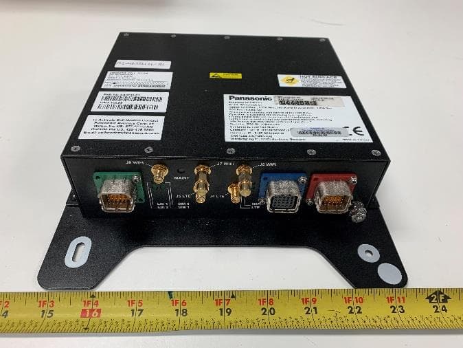
U6YRDAA8190
Jul 14, 2021Enhanced Cell Modem
Equipment Class
NII - Unlicensed National Information Infrastructure TX
U6YRD-AA8101
Oct 05, 2007GSM Cellular Data Modem
Equipment Class
PCB - PCS Licensed Transmitter
U6YRD-FW7874
May 20, 2007SM-17 Smart Monitor
Equipment Class
NII - Unlicensed National Information Infrastructure TX