U73-21165046Intellistripe 65 Contactless Cad Reader, 21165046
Magtek Incorporated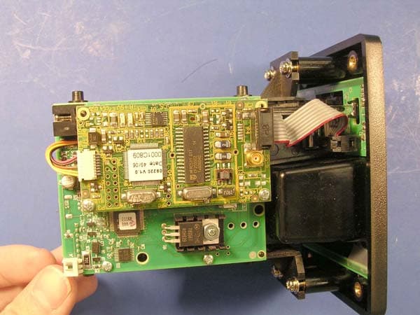
Click to zoom
Application Details
- Equipment Class
- DXX - Part 15 Low Power Communication Device Transmitter
- Date of Grant
- May 01, 2007
- Application Purpose
- Original Equipment
- Date of Application
- Apr 29, 2007
- Equipment Note
- Intellistripe 65 Contactless Cad Reader, 21165046
- Frequency Range
- 13.56000000 - 13.56000000
- Company
- Magtek Incorporated
- Country
- United States
Documents & Files
Document Text
Text extracted from the exhibit documents filed with the FCC. Open a document above to read the original.
Users Manual
IntelliStripe 65 USB/RS-232 INSERTION READER TECHNICAL REFERENCE MANUAL Manual Part Number: 99875339 Rev 3 MARCH 2007 REGISTERED TO ISO 9001:2000 20725 South Annalee Avenue Carson, CA 90746 Phone: (310) 631-8602 FAX: (310) 631-3956 Technical Support: (651) 415-6800 www.magtek.com ii Copyright © 2000-2007 MagTek ® , Inc. Printed in the United States of America Information in this document is subject to change without notice. No part of this document may be reproduced or transmitted in any form or by any means, electronic or mechanical, for any purpose, without the express written permission of MagTek, Inc. MagTek is a registered trademark of MagTek, Inc. IntelliStripe ® is a registered trademark of MagTek, Inc. Torx® is a registered trademark of Textron, Inc. REVISIONS Rev Number Date Notes 1 8 May 2006 Initial Release 2 13 Feb 2007 Added RoHS Statement. Updated to show OTI contactless module 3 26 Mar 2007 Clarified FCC statement; updated operating temperature range iii LIMITED WARRANTY MagTek warrants that the products sold to Reseller pursuant to this Agreement will perform in accordance with MagTek’s published specifications. This warranty shall be provided only for a period of one year from the date of the shipment of the product from MagTek (the “Warranty Period”). This warranty shall apply only to the original purchaser unless the buyer is authorized by MagTek to resell the products, in which event, this warranty shall apply only to the first repurchase. During the Warranty Period, should this product fail to conform to MagTek’s specifications, MagTek will, at its option, repair or replace this product at no additional charge except as set forth below. Repair parts and replacement products will be furnished on an exchange basis and will be either reconditioned or new. All replaced parts and products become the property of MagTek. This limited warranty does not include service to repair damage to the product resulting from accident, disaster, unreasonable use, misuse, abuse, customer’s negligence, Reseller’s negligence, or non-MagTek modification of the product. MagTek reserves the right to examine the alleged defective goods to determine whether the warranty is applicable. Without limiting the generality of the foregoing, MagTek specifically disclaims any liability or warranty for goods resold in other than MagTek’s original packages, and for goods modified, altered, or treated by customers. Service may be obtained by delivering the product during the warranty period to MagTek (20801 S. Annalee Ave., Carson, CA 90746). If this product is delivered by mail or by an equivalent shipping carrier, the customer agrees to insure the product or assume the risk of loss or damage in transit, to prepay shipping charges to the warranty service location and to use the original shipping container or equivalent. MagTek will return the product, prepaid, via a three (3) day shipping service. A Return Material Authorization (RMA) number must accompany all returns. MAGTEK MAKES NO OTHER WARRANTY, EXPRESS OR IMPLIED, AND MAGTEK DISCLAIMS ANY WARRANTY OF ANY OTHER KIND, INCLUDING ANY WARRANTY OF MERCHANTABILITY OR FITNESS FOR A PARTICULAR PURPOSE. EACH PURCHASER UNDERSTANDS THAT THE MAGTEK PRODUCT IS OFFERED AS IS. IF THIS PRODUCT DOES NOT CONFORM TO MAGTEK’S SPECIFICATIONS, THE SOLE REMEDY SHALL BE REPAIR OR REPLACEMENT AS PROVIDED ABOVE. MAGTEK’S LIABILITY, IF ANY, TO RESELLER OR TO RESELLER’S CUSTOMERS, SHALL IN NO EVENT EXCEED THE TOTAL AMOUNT PAID TO MAGTEK BY RESELLER UNDER THIS AGREEMENT. IN NO EVENT WILL MAGTEK BE LIABLE TO THE RESELLER OR THE RESELLER’S CUSTOMER FOR ANY DAMAGES, INCLUDING ANY LOST PROFITS, LOST SAVINGS OR OTHER INCIDENTAL OR CONSEQUENTIAL DAMAGES ARISING OUT OF THE USE OF OR INABILITY TO USE SUCH PRODUCT, EVEN IF MAGTEK HAS BEEN ADVISED OF THE POSSIBILITY OF SUCH DAMAGES, OR FOR ANY CLAIM BY ANY OTHER PARTY. LIMITATION ON LIABILITY EXCEPT AS PROVIDED IN THE SECTIONS RELATING TO MAGTEK’S LIMITED WARRANTY, MAGTEK’S LIABILITY UNDER THIS AGREEMENT IS LIMITED TO THE CONTRACT PRICE OF THE PRODUCTS. MAGTEK MAKES NO OTHER WARRANTIES WITH RESPECT TO THE PRODUCTS, EXPRESSED OR IMPLIED, EXCEPT AS MAY BE STATED IN THIS AGREEMENT, AND MAGTEK DISCLAIMS ANY IMPLIED WARRANTY, INCLUDING WITHOUT LIMITATION ANY IMPLIED WARRANTY OF MERCHANTABILITY OR FITNESS FOR A PARTICULAR PURPOSE. MAGTEK SHALL NOT BE LIABLE FOR CONTINGENT, INCIDENTAL, OR CONSEQUENTIAL DAMAGES TO PERSONS OR PROPERTY. MAGTEK FURTHER LIMITS ITS LIABILITY OF ANY KIND WITH RESPECT TO THE PRODUCTS, INCLUDING ANY NEGLIGENCE ON ITS PART, TO THE CONTRACT PRICE FOR THE GOODS. MAGTEK’S SOLE LIABILITY AND BUYER’S EXCLUSIVE REMEDIES ARE STATED IN THIS SECTION AND IN THE SECTION RELATING TO MAGTEK’S LIMITED WARRANTY. FCC WARNING STATEMENT This equipment has been tested and found to comply with the limits for Class B digital device, pursuant to Part 15 of FCC Rules. These limits are designed to provide reasonable protection against harmful interference when the equipment is operated in a residential environment. This equipment generates, uses, and can radiate radio frequency energy and, if not installed and used in accordance with the instruction manual, may cause harmful interference to radio communications. However, there is no guarantee that interference will not occur in a particular installation. Changes or modifications not expressly approved by MagTek could void the user's authority to operate the equipment. FCC COMPLIANCE STATEMENT This device complies with Part 15 of the FCC Rules. Operation of this device is subject to the following two conditions: (1) This device may not cause harmful interference; and (2) this device must accept any interference received, including interference that may cause undesired operation. CANADIAN DOC STATEMENT This digital apparatus does not exceed the Class B limits for radio noise for digital apparatus set out in the Radio Interference Regulations of the Canadian Department of Communications. Le présent…
Text truncated - open the document above for the full version.
Cover Letter(s)
Non-Conformities FCC ID: U73-21165046 (CKC CS Ref # E07-000019-01) The items listed below represent requests for information following review of this application for certification under United S tates (FCC) regulations. . Further question may arise pending review of responses to these items. OK # Non-Conformity or Co mment Submitted Response Respondent / Date of Response √ 1 Please explain non-compliant data listed on page 25 and 28 of test report. Explanation provided. Mary Ellen/4-3-07 √ 2 Schematic diagrams do not appear to include the radio portion of the device. Specifically missing is the 24 and 13.56MHz clocks driving the radio IC. Please provide all schematics pertaining to the equipment as required by 2.1033. Transceiver schematics have been uploaded. Mary Ellen/4-3-07 x 3 The users manual discusses use of a remote antenna. The test report shows only measurement data for one configuration and does not identify which antenna was used. Please identify each an tenna to be certified for use with this system and number of antennas intended to be used with the equipment. New user’s manual uploaded – antenna is integral according to new test report. See NC-2 Mary Ellen/4-3-07 √ 4 The users manual appears to be mi ssing compliance statement required by 15.21. Please provide an updated us ers manual including this statement. New user’s manual uploaded Mary Ellen/4-3-07 5 6 Non-Conformities FCC ID: U73-21165046 (CKC CS Ref # E07-000019-02) The items listed below represent requests for information following review of this application for certification under United S tates (FCC) regulations. . Further question may arise pending review of responses to these items. OK # Non-Conformity or Co mment Submitted Response Respondent / Date of Response X 1 Test report states that the antenna is integral, but the user’s manual on page 13 implies that there are at least tw o different ways of extending the coil antenna via either ribbon cable or coax cable. If this is true, why weren’t these different antenna positions checke d to determine the worst case of the spurious emissions or the fundamental. The OTI transmitter module has both options to use Ribbon or Coax cables to connect to different type of Antenna, but the only antenna we are going to use with this unit has only connector for ribbon cable. It does not support CKC labs 4/5/07 Coax connection. Typically the Coax cable has better shielding compare to ribbon cable. The testing occurred with the ribbon cable. X TCB Notes: 1)Antenna is internal to the equipment. 2)Device on the table in front of the EUT is to wave the card in order to ensure EUT circuitry remains active during the test. Non-Conformities FCC ID: U73-21165046 (CKC CS Ref # E07-000019-03) The items listed below represent requests for information following review of this application for certification under United S tates (FCC) regulations. . Further question may arise pending review of responses to these items. OK # Non-Conformity or Co mment Submitted Response Respondent / Date of Response X 1 Grantee Code U4T is no longer valid. This issue typically arises due to a lack of on-time payment with the FCC. Pleas e re-apply for Grantee code with the FCC and ensure payment is received by the FCC within the allowed 30 calendar days. Grantee updated code CKCLABS 4/30/07 X 2 The likelihood of original grantee code being available to Magtek is minimal. Therefore, Magtek will most likely be given a different grantee code. This necessitates all documentation containing the original grantee code U4T to be updated. This includes the following exhibits: ID Label, ID Label placement, Confidentiality Letter, an d any other documentation which may contain the lost grantee code. Pl ease provide all necessary updated documentation after receiving the new grantee code. Updated documentation provided CKCLABS 4/30/07
External Photos
Front Back Top Bottom Side 1 Side 2
Internal Photos
Antenna 1 Antenna 2 Antenna 3 Logic PCB Transmitter PCB Top Transmitter PCB Bottom
Operational Description
INTEGRATED CIRCUITS MF RC531 ISO 14443 Reader IC April 2005 Short Form Specification Revision 3.2 Philips Semiconductors Philips SemiconductorsShort Form Specification Rev. 3.2 April 2005 ISO 14443A Reader ICMF RC531 2PUBLIC CONTENTS 1INTRODUCTION.......................................................3 1.1Scope.......................................................................3 1.2Features...................................................................3 1.3Applications..............................................................3 2BLOCK DIAGRAM....................................................4 3MF RC531 PINNING.................................................5 3.1Pinning Diagram........................................................5 3.2Pin Description..........................................................6 3.2.1Antenna Interface.....................................................6 3.2.2Analog Supply..........................................................6 3.2.3Digital Supply............................................................6 3.2.4Auxillary Pin..............................................................6 3.2.5Reset Pin...................................................................7 3.2.6Oscillator...................................................................7 3.2.7MIFARE Interface...................................................7 3.2.8Parallel Interface.......................................................7 3.2.9SPI Compatible Interface..........................................8 3.3Applications..............................................................8 3.3.1Connecting Different μController's............................8 3.3.2Application Example..................................................9 4MIFARE ® CLASSIC RELATED ITEMS...................10 4.1CRYPTO I: Card Authentication.............................10 4.1.1Initiating Card Authentication..................................10 4.1.2Second Part of Card Authentication........................10 5ELECTRICAL SPECIFICATION..............................11 5.1DC Characteristics..................................................11 5.2Start up Characteristics..........................................11 6REVISION HISTORY..............................................12 MIFARE is a registered trademark of Philips Electronics N.V Philips SemiconductorsShort Form Specification Rev. 3.2 April 2005 ISO 14443A Reader ICMF RC531 3PUBLIC 1 INTRODUCTION 1.1 Scope The MF RC531 is member of a new family of highly integrated reader ICs for contactless communication at 13.56 MHz. This reader IC family utilises an outstanding modulation and demodulation concept completely integrated for all kinds of passive contactless communication methods and protocols at 13.56 MHz. The MF RC531 is pin- compatible to the MF RC500, the MF RC530 and the SL RC400. The Philips IC MF RC531 supports all layers of the ISO/IEC 14443A/B communication scheme, given correct implementation of additional components, like oscillator, power supply, coil etc. and provided that standardised protocols, e.g. like ISO/IEC 14443-4 and/or ISO/IEC 14443 type B anticollision are correctly implemented. The use of this Philips IC according to ISO14443 Type B might infringe third party patent rights. The MF RC531 supports contactless communication using MIFARE ® Higher Baudrates. The internal transmitter part is able to drive an antenna designed for proximity operating distance (up to 100 mm) directly without additional active circuitry. The receiver part provides a robust and efficient implementation of a demodulation and decoding circuitry for signals from ISO14443 compatible transponders. The digital part handles the complete ISO14443 framing and error detection (Parity & CRC). Additionally it supports the fast MIFARE ® Classic security algorithm to authenticate MIFARE Classic (e.g. MIFARE ® Standard) products. A comfortable parallel interface, which can be directly connected to any 8-bit μ-Processor gives high flexibility for the reader/terminal design. Additionally a SPI compatible interface is supported. A purchaser of this Philips IC has to take care for appropriate third party patent licenses. 1.2 Features • Highly integrated analog circuitry to demodulate and decode card response • Buffered output drivers to connect an antenna with minimum number of external components • Proximity operating distance (up to 100 mm) • Supports ISO 14443 • Supports MIFARE ® Dual Interface Card ICs and supports MIFARE ® Classic protocol • Supports contactless communication with higher baudrates up to 424kHz • Crypto1 and secure non-volatile internal key memory • Pin-compatible to the MF RC500, MF RC530 and the SL RC400 • Parallel μ-Processor interface with internal address latch and IRQ line • SPI compatible interface • Flexible interrupt handling • Automatic detection of the used μ-Processor interface type • Comfortable 64 byte send and receive FIFO- buffer • Hard reset with low power function • Power down mode per software • Programmable timer • Unique serial number • Bit- and byte-oriented framing • Internal oscillator buffer to connect 13.56 MHz quartz, optimised for low phase jitter • 3.3 V to 5 V operation for transmitter (antenna driver) in short range and proximity applications • 3.3 V or 5V operation for the digital part 1.3 Applications The MF RC531 is tailored to fit the requirements of various applications using contactless communication based on ISO/IEC 14443 standard where cost-effectiveness, small size, high performance with a single voltage supply are important. • Public transport terminals • Handheld terminals • On board units • Contactless PC terminals • Metering • Contactless public phones Philips SemiconductorsShort Form Specification Rev. 3.2 April 2005 ISO 14443A Reader ICMF RC531 4PUBLIC 2 BLOCK DIAGRAM The block diagram shows the main internal parts of the MF RC531. The parallel μController interface automatically detects the kind of 8 bit…
Text truncated - open the document above for the full version.
Operational Description
OTI Confidential and Proprietary OTI SCI1000 Transmitter Description for FCC Type of equipment X Stand-alone (Equipment with or without its own control provisions) Combined equipment (Equipment where the radio part is fully integrated within another type of equipment) Plug-in card (Equipment intended for a variety of host systems) Intended use Condition of use fixed Always at a distance more than 2 m from all people mobile Always at a distance more than 20 cm from all people portable May operate at a distance closer than 20 cm to human body Assigned frequency range ..........MHz Operating frequency range ...13.56MHz RF channel spacing ..........kHz At transmitter 50 Ω RF output connector 26dBm Maximum rated output power Effective radiated power (for equipment with no RF connector) ..........dBm X No continuous variable stepped variable with stepsize ..........dB minimum RF power ..........dBm Is transmitter output power variable? Yes maximum RF power ..........dBm Antenna connection with temporary RF connector X unique coupling standard connector integral without temporary RF connector Antenna/s technical characteristics Type Manufacturer Model number Gain Loop antenna Need to supply NA Transmitter 99% power bandwidth ..........kHz Transmitter aggregate data rate/s 848Kbps Transmitter aggregate symbol (baud) rate/s ..........Msymbols (MBaud) per second Type of modulation ASK Type of multiplexing Modulating test signal (baseband) Repetitive REQA/B according to ISO14443-2&3 Maximum transmitter duty cycle in normal use 100% Tx ON time ..........msec Period ..........msec Transmitter duty cycle supplied for test 100% Tx ON time ..........msec Period ..........msec Transmitter power source Battery Nominal rated voltage ..........VDC Battery type Ni- Cd, Lithium, Lead- Acid, other DC Nominal rated voltage 5VDC+-5% AC mains Nominal rated voltage ..........VAC Frequency ..........Hz Is there common power source for transmitter and receiver yes no Emission designator according to Attachment 10 Frequency hopping (FHSS) Digital transmission system (DTS) Spread spectrum technique used Hybrid Spread spectrum parameters for transmitters tested per FCC 15.247 only chip sequence length ..........bits DSSS spectrum width ..........MHz total number of hops .......... dwell time ..........msec bandwidth per hop ..........MHz FHSS max. separation of hops ..........MHz Crystals: • 24.00MHz – Microprocessor. • 13.56MHz – Transceiver. Hemy Itay OTI
Operational Description
SCI1000 Operational Description The SCI1000 OEM reader is an inexpensive, compact radio frequency communications electronic interface unit. Bi-directional RF communication to contactless smart cards, serial communication to application controller and rich set of macro commands make it the keystone in contactless smart card systems.. The SCI1000 can be integrated into existing systems. Using TTL level NRZ communication between reader and Host, the SCI1000 allows bi-directional, communication between the Host and passive, contactless smart card. The SCI1000 OEM Reader Board serves as a smart interface unit between the application controller and: • ISO 14443 Type B Contactless smart cards. • ISO 14443 Type A Contactless smart cards. • Mifare Contactless smart cards At the Host’s command, the SCI1000 generates and modulates a 13.56 MHz carrier signal for the transmission of power, commands and data to an in-range smart card. The SCI1000 detects the, signal encoded by the card automatically choosing the modulation technique required by the card. Read and write operations have equal data rates and range. Transceiver circuitry: The transceiver is based on a single Philips RC531 chip. Inductive coupling to contactless cards requires constant transmission of 13.56MHz carrier via a loop antenna (unlike conventional radios which mute their transmitter during receiving time). Data transfer to the card is achieved using amplitude modulation as defined in ISO14443 standard with two possible scenarios: Type A and Type B. In order to transfer data from the card to the reader the card modulate its impedance using double modulation technique where an 847KHz subcarrier is further modulated with the data as also described ISO14443 standard. The load modulation also modulates the antenna impedance as seen from the reader, affecting amplitude and phase shift modulations in the transmitted signal. These fluctuations are sensed by the chip receiver which also performs the incoming digital data retrieval. Inductive Loop Antenna: The close range inductive coupling is supported by a loop antenna, with an attempt to generate maximum magnetic field while maintaining the Electrical field at minimum, especially at far field. The loop antenna is matched to 50ohm in order to fit the 50ohm feeding coax cable. Single chip Microprocessor: A single chip microprocessor performs all the control and communication tasks, both to/from the host and the transceiver chip. Digital IO The SCI1000 supports 3 buffered outputs which drives 3 indicating LEDs, used for status indication.. Operating Voltage The SCI1000 operates on regulated 5VDC/350mAmax.
Test Report
Page 1 of 54 Report No.: FC07-013A ADDENDUM TO MAGTEK INCORPORATED TEST REPORT FC07-013 FOR THE INTELLISTRIPE 65 CONTACTLESS CARD READER, 211650XX FCC PART 15 SUBPART C SECTIONS 15.207 & 15.225 AND SUBPART B SECTIONS 15.107 & 15.109 CLASS B COMPLIANCE DATE OF ISSUE: MARCH 23, 2007 PREPARED FOR: Magtek Incorporated 20725 South Annalee Avenue Carson, CA 90746 PREPARED BY: Mary Ellen Clayton CKC Laboratories, Inc. 5046 Sierra Pines Drive Mariposa, CA 95338 P.O. No.: 86878 W.O. No.: 84991 Date of test: February 23 - March 1, 2007 Report No.: FC07-013A This report contains a total of 54 pages and may be reproduced in full only. Partial reproduction may only be done with the written consent of CKC Laboratories, Inc. The results in this report apply only to the items tested, as identified herein. Page 2 of 54 Report No.: FC07-013A TABLE OF CONTENTS Administrative Information .............................................................................................3 Approvals .........................................................................................................................3 Conditions for Compliance ..............................................................................................3 FCC 15.31(m) Number Of Channels ...............................................................................4 FCC 15.33(a) Frequency Ranges Tested .........................................................................4 FCC 15.203 Antenna Requirements ................................................................................4 EUT Operating Frequency ...............................................................................................4 Temperature And Humidity During Testing....................................................................4 Equipment Under Test (EUT) Description ......................................................................5 Equipment Under Test .....................................................................................................5 Peripheral Devices ...........................................................................................................5 Report of Emissions Measurements.................................................................................7 Testing Parameters...............................................................................................7 FCC 15.107 Conducted Emissions ......................................................................9 FCC 15.109 Radiated Emissions .........................................................................15 FCC 15.207 Conducted Emissions ......................................................................24 FCC 15.225 Radiated Emissions .........................................................................36 Occupied Bandwidth –20dB ................................................................................46 FCC 15.225(a), (b), (c) Emissions Mask .............................................................48 Bandedge Plot ......................................................................................................50 Frequency Stability and Voltage Variations ........................................................53 Page 3 of 54 Report No.: FC07-013A ADMINISTRATIVE INFORMATION DATE OF TEST: February 23 - March 1, 2007 DATE OF RECEIPT: February 23, 2007 MANUFACTURER: Magtek Incorporated 20725 South Annalee Avenue Carson, CA 90746 REPRESENTATIVE: Brian Tahamzadeh TEST LOCATION: CKC Laboratories, Inc. 110 Olinda Place Brea, CA 92823 TEST METHOD: ANSI C63.4 (2003) PURPOSE OF TEST: Original Report: To demonstrate the compliance of the IntelliStripe 65 Contactless Card Reader, 211650XX with the requirements for FCC Part 15 Subpart C Sections 15.207 & 15.225 and Subpart B Sections 15.107 & 15.109 Class B devices. Addendum A: To clarify data on pages 25 and 28 with no new testing. APPROVALS Steve Behm, Director of Engineering Services QUALITY ASSURANCE:TEST PERSONNEL: Joyce Walker, Quality Assurance Administrative Manager Eddie Wong, EMC Engineer CONDITIONS FOR COMPLIANCE No modifications to the EUT were necessary to comply. Page 4 of 54 Report No.: FC07-013A FCC 15.31(m) Number Of Channels This device operates on a single channel. FCC 15.33(a) Frequency Ranges Tested 15.107 Conducted Emissions: 150 kHz – 30 MHz 15.109 Radiated Emissions: 9 kHz – 1000 MHz 15.207 Conducted Emissions: 150 kHz – 30 MHz 15.225 Radiated Emissions: 9 kHz – 1000 MHz FCC 15.203 Antenna Requirements The antenna is an integral part of the EUT and is non-removable; therefore the EUT complies with Section 15.203 of the FCC rules. EUT Operating Frequency The EUT was operating at 13.56 MHz. Temperature And Humidity During Testing The temperature during testing was within +15°C and + 35°C. The relative humidity was between 20% and 75%. Page 5 of 54 Report No.: FC07-013A EQUIPMENT UNDER TEST (EUT) DESCRIPTION The customer declares the EUT tested by CKC Laboratories was representative of a production unit. The following model name at the time of testing by CKC Laboratories was: 21165046 It was actually 21165046 I65 B2,M3,C1,SG,L3,1H,H4,S1,LP,CF. I65 designates it is an Intellistripe 65 card reader and the 46 is for the contactless option. A description of the other options is on the following page. Since the time of testing the manufacturer has chosen to use the following model name in its place. Any differences between the names does not affect their EMC characteristics and therefore complies to the level of testing equivalent to the tested model name shown on the data sheets: 211650XX. A list of the options represented by XX is on the following page. EQUIPMENT UNDER TEST Power Supply Manuf: DVE Model: DSA-0151D-12 Serial: NA FCC ID: NA IntelliStripe 65 Contactless Card Reader Manuf: Magtek Incorporated Model: 211650XX Serial: NA FCC ID: pending PERIPHERAL DEVICES The EUT was tested with the following peripheral device(s): Laptop Manuf: Dell Model: Inspiron 8…
Text truncated - open the document above for the full version.
Test Setup Photos
FCC 15.107 CONDUCTED EMISSIONS Test Setup Photos FCC 15.109 RADIATED EMISSIONS Test Setup Photos Occupied Bandwidth and Emissions Mask Test Setup Photos Frequency Stability Test Setup Photos
Contact Information
Applicant
Kevin Gin
Technical Contact
CKC Laboratories, Inc.Mary Ellen Clayton
[email protected]209-966-5240
5046 Sierra Pines Dr. · Mariposa · United States
Test Firm
CKC Laboratories, Inc.Steve Behm
Technical Specifications
| # | Rule Parts | Frequency Range | Power Output |
|---|---|---|---|
| 1 | 15C | 13.56 MHz - 13.56 MHz | - |
Other Applications from Magtek Incorporated

U73-210780DPX
Jan 19, 2022Contactless Secure Card Reader
Equipment Class
DXT - Part 15 Low Power Transceiver, Rx Verified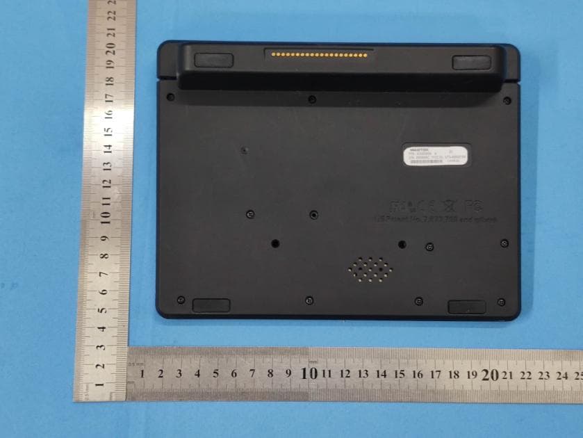
U73-40000102
Nov 03, 2020DynaGlass
Equipment Class
DSS - Part 15 Spread Spectrum Transmitter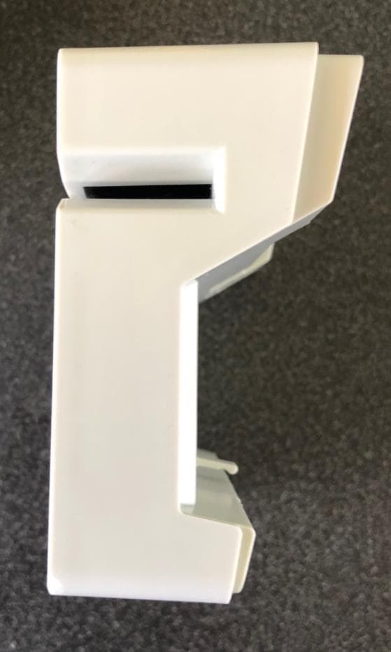
U73-210780XX
Jun 30, 2020Secure Card Reader
Equipment Class
DXT - Part 15 Low Power Transceiver, Rx Verified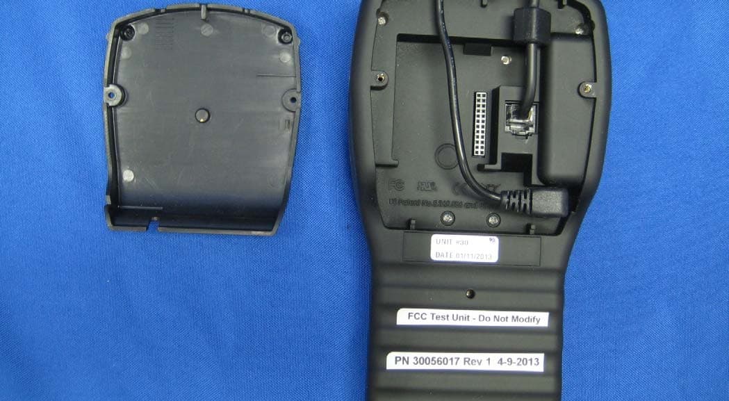
U73-30056015
Aug 20, 2013DynaPro
Equipment Class
DXT - Part 15 Low Power Transceiver, Rx Verified
U73-30056017
Aug 20, 2013DynaPro
Equipment Class
DXT - Part 15 Low Power Transceiver, Rx Verified