U73-40000102DynaGlass
Magtek Incorporated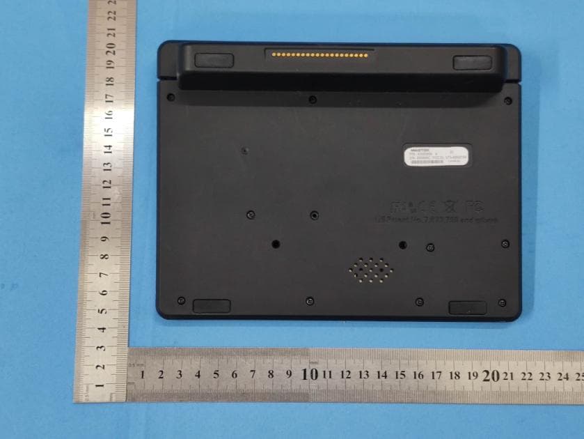
Click to zoom
Application Details
- Equipment Class
- DSS - Part 15 Spread Spectrum Transmitter
- Date of Grant
- Nov 03, 2020
- Application Purpose
- Original Equipment
- Date of Application
- Nov 03, 2020
- Equipment Note
- DynaGlass
- Frequency Range
- 2402.00000000 - 2480.00000000
- Company
- Magtek Incorporated
- Country
- United States
Documents & Files
Document Text
Text extracted from the exhibit documents filed with the FCC. Open a document above to read the original.
Users Manual
1 DynaGlass Operation Manual September 2020 Version 001 Content 1 Operation Guide........................................................................3 2 Transactions Guide.....................................................................4 2 1. Operation Guide To use a MSR card To swipe card, make sure the MSR is on the bottom side, press the card to the bottom of the slot and swipe it. The MSR card can be swiped with the front of card or the back of card. 3 To use a IC card,the IC card chip should face the LCD. To use a contactless card ,place the contactless card above the logo shown on the LCD screen. 2 Transactions Guide Refer to the guide of the software. 4 FCC Statement This equipment has been tested and found to comply with the limits for a Class B digital device, pursuant to Part 15 of the FCC Rules. These limits are designed to provide reasonable protection against harmful interference in a residential installation. This equipment generates uses and can radiate radio frequency energy and, if not installed and used in accordance with the instructions, may cause harmful interference to radio communications. However, there is no guarantee that interference will not occur in a particular installation. If this equipment does cause harmful interference to radio or television reception, which can be determined by turning the equipment off and on, the user is encouraged to try to correct the interference by one or more of the following measures: -- Reorient or relocate the receiving antenna. -- Increase the separation between the equipment and receiver. -- Connect the equipment into an outlet on a circuit different from that to which the receiver is connected. -- Consult the dealer or an experienced radio/TV technician for help. Changes or modifications not expressly approved by the party responsible for compliance could void the user's authority to operate the equipment. IC STATEMENT This device complies with Industry Canada’s licence-exempt RSSs. Operation is subject to the following two conditions: (1) This device may not cause interference; and (2) This device must accept any interference, including interference that may cause undesired operation of the device. Le présent appareil est conforme aux CNR d'Industrie Canada applicables aux appareils radio exempts de licence. L'exploitation est autorisée aux deux conditions suivantes : (1) l'appareil ne doit pas produire de brouillage, et (2) l'utilisateur de l'appareil doit accepter tout brouillage radioélectrique subi, même si le brouillage est susceptible d'en compromettre le fonctionnement. SAR: The radiated output power of this device is below the FCC radio frequency exposure limits. Nevertheless, the device should be used in such a manner that the potential for human contact is minimized during normal operation. The exposure standard for wireless devices employs a unit of measurement known as the Specific Absorption Rate, or SAR. The SAR limit set by the FCC is 1.6 W/Kg. Tests for SAR are conducted using standard operating positions accepted by the FCC with the device 5 transmitting at its highest certified power level in all tested frequency bands. Although the SAR is determined at the highest certified power level, the actual SAR level of the device while operating can be well below the maximum value. This is because the device is designed to operate at multiple power levels so as to use only the power required to reach the network. In general, the closer you are to a wireless base station antenna, the lower the power output. To avoid the possibility of exceeding the FCC radio frequency exposure limits, human proximity to the antenna should be minimized. For body worn operation, this device has been tested and meets the FCC RF exposure. Guidelines when used with an accessory designated for this product or when used with an accessory that contains no metal and that positions the handset a minimum of 0mm from the body.
Cover Letter(s)
Differences Declaration To whom concern, We company Magtek Incorporated hereby declares: The product models 40000102, 40000101 are identical in the same PCB layout, interior structure and electrical circuits, The differences are appearance color and model name for commercial purpose. Authorized signature: Date: 2020-08-31
Cover Letter(s)
Magtek Incorporated Letter of Authorization Company: Magtek Incorporated Address: 1710 Apollo Court, seal beach, California 90740, United States Product Type: DynaGlass Model Number(s): 40000102, 40000101 Product Description: DynaGlass We authorize MiCOM Labs Inc., 575 Boulder Court, Pleasanton, California 94566, USA, to act on our behalf on all matters concerning the certification of above named equipment. We declare that MiCOM Labs Inc. is allowed to forward all information related to the approval and certification of equipment to the regulatory agencies as required and to discuss any issues concerning the approval application. Any and all acts carried out by MiCOM Labs on our behalf shall have the same effect as acts of our own. Signature: Date: 2020-08-31 Name: Hamid Manesh Title: Manager Company: Magtek Incorporated
Cover Letter(s)
Magtek Incorporated Office of Engineering Technology Federal Communications Commission 7435 Oakland Mills Road Columbia, MD 21046 USA Date: 2020-08-31 Subject; Request for Confidentiality FCC ID: U73-40000102 To Whom It May Concern, Pursuant to the provisions of the Commission’s rules Title 47 Sections §0.457 and §0.459, we are requesting the Commission to withhold the following attachment(s) as confidential documents from public disclosure indefinitely. These documents contain detailed system and equipment descriptions and are considered as proprietary information in operation of the equipment. The public disclosure of these documents might be harmful to our company and would give competitors an unfair advantage in the market. Schematic Diagram Block Diagram Operational Description FCC Software Security Requirements for UNII devices In additional to above mentioned documents, in order to comply with the marketing regulations in Title 47 CFR §2.803 and the importation rules in Title 47 CFR §2.1204, while ensuring that business sensitive information remains confidential until the actual marketing of newly authorized devices, we request Short Term Confidentiality of the following attachment(s); External Photos Test Setup Photos Internal Photos User Manual For 45 days, pursuant to Public Notice DA 04-1705. OR For 180 days pursuantto KDB 726920 D01. It is our understanding that all measurement test reports, FCC ID label format and correspondence during the certification review process cannot be granted as confidential documents and this information will be available for public review once the grant of equipment authorization is issued. Sincerely, Signature: Name: Hamid Manesh Title: Manager
External Photos
Test Model No.: 40000102
ID Label/Location Info
Label location
Internal Photos
Test Model No.: 40000102
Test Report
Global United Technology Services Co., Ltd. Report No.: GTS202007000071-01 1 Cover Page TEST REPORT Applicant: FCC: Magtek Incorporated IC: MagTek Inc Address of Applicant: FCC: 1710 Apollo Court, seal beach, California 90740, United States IC: 1710 Apollo Court Seal Beach CA 90740 United States Manufacturer: FCC: Magtek Incorporated IC: MagTek Inc Address of Manufacturer: FCC: 1710 Apollo Court, seal beach, California 90740, United States IC: 1710 Apollo Court Seal Beach CA 90740 United States Equipment Under Test (EUT) Product Name: DynaGlass Model No.: 40000102, 40000101 Trade Mark: MAGTEK FCC ID: U73-40000102 IC: 23169-40000102 Applicable standards: FCC CFR Title 47 Part 15 Subpart C Section 15.247 RSS-247 Issue 2 RSS-Gen Issue 5 Date of sample receipt: July 07, 2020 Date of Test: July 08, 2020-August 31, 2020 Date of report issued: August 31, 2020 Test Result : PASS * * In the configuration tested, the EUT complied with the standards specified above. Authorized Signature: Robinson Lo Laboratory Manager This results shown in this test report refer only to the sample(s) tested, this test report cannot be reproduced, except in full, without prior written permission of the company. The report would be invalid without specific stamp of test institute and the signatures of compiler and approver. Page 1 of 49 Report No.: GTS202007000071-01 2 Version Version No. Date Description 00 August 31, 2020 Original Prepared By: Date: August 31, 2020 Project Engineer Check By: Date: August 31, 2020 Reviewer Global United Technology Services Co., Ltd. No. 123-128, Tower A, Jinyuan Business Building, No.2, Laodong Industrial Zone, Xixiang Road, Baoan District, Shenzhen, Guangdong, China 518102 Telephone: +86 (0) 755 2779 8480 Fax: +86 (0) 755 2779 8960 Page 2 of 49 Report No.: GTS202007000071-01 3 Contents Page 1 COVER PAGE .......................................................................................................................................... 1 2 VERSION .................................................................................................................................................. 2 3 CONTENTS .............................................................................................................................................. 3 4 TEST SUMMARY ..................................................................................................................................... 4 5 GENERAL INFORMATION ...................................................................................................................... 5 5.1 GENERAL DESCRIPTION OF EUT ......................................................................................................... 5 5.2 TEST MODE ........................................................................................................................................ 7 5.3 DESCRIPTION OF SUPPORT UNITS ....................................................................................................... 7 5.4 DEVIATION FROM STANDARDS ............................................................................................................. 7 5.5 ABNORMALITIES FROM STANDARD CONDITIONS .................................................................................... 7 5.6 TEST FACILITY .................................................................................................................................... 7 5.7 TEST LOCATION .................................................................................................................................. 7 6 TEST INSTRUMENTS LIST ..................................................................................................................... 8 7 TEST RESULTS AND MEASUREMENT DATA .................................................................................... 10 7.1 ANTENNA REQUIREMENT ................................................................................................................... 10 7.2 CONDUCTED EMISSIONS ................................................................................................................... 11 7.3 CONDUCTED PEAK OUTPUT POWER .................................................................................................. 14 7.4 20DB EMISSION BANDWIDTH & 99% OCCUPY BANDWIDTH ................................................................ 18 7.5 CARRIER FREQUENCIES SEPARATION ................................................................................................ 22 7.6 HOPPING CHANNEL NUMBER ............................................................................................................. 26 7.7 DWELL TIME ..................................................................................................................................... 28 7.8 BAND EDGE ...................................................................................................................................... 30 7.8.1 Conducted Emission Method ..................................................................................................... 30 7.8.2 Radiated Emission Method ........................................................................................................ 34 7.9 SPURIOUS EMISSION ......................................................................................................................... 37 7.9.1 Conducted Emission Method ..................................................................................................... 37 7.9.2 Radiated Emission Method ........................................................................................................ 39 7.10 FREQUENCY STABILITY ..................................................................................................................... 47 8 TEST SETUP PHOTO ............................................................................................................................ 49 9 EUT CONSTRUCTIONAL DETA…
Text truncated - open the document above for the full version.
Test Setup Photos
Test Model No.: 40000102 Radiated Emission Conducted Emissions
Contact Information
Applicant
Kevin Gin
Technical Contact
Test Firm
Global United Technology Services Co. Ltd.Robinson Lo
Technical Specifications
| # | Rule Parts | Frequency Range | Power Output |
|---|---|---|---|
| 1 | 15C | 2.40 GHz - 2.48 GHz | 1.40 mW |
Other Applications from Magtek Incorporated

U73-210780DPX
Jan 19, 2022Contactless Secure Card Reader
Equipment Class
DXT - Part 15 Low Power Transceiver, Rx Verified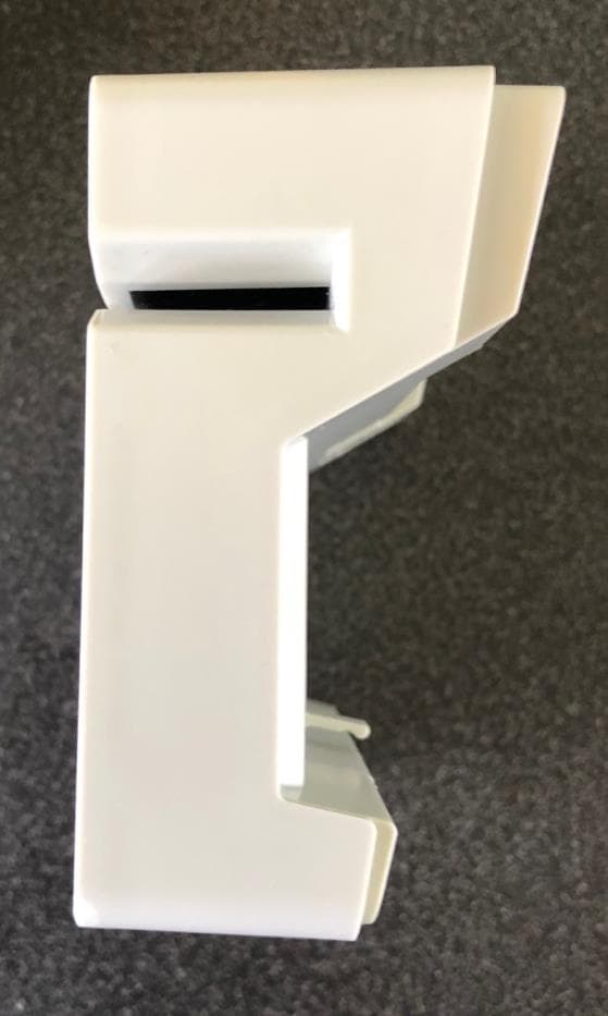
U73-210780XX
Jun 30, 2020Secure Card Reader
Equipment Class
DXT - Part 15 Low Power Transceiver, Rx Verified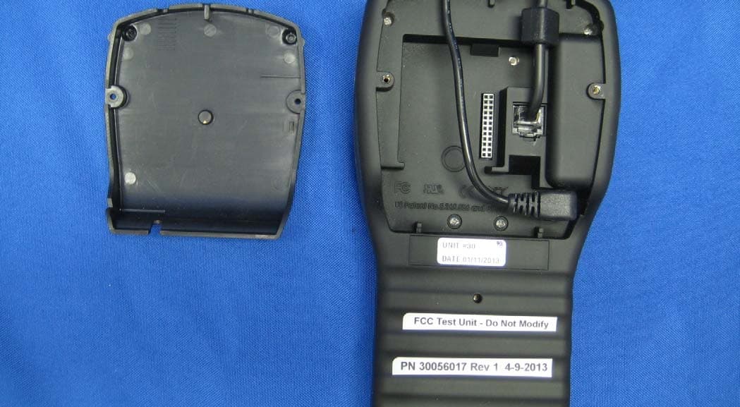
U73-30056015
Aug 20, 2013DynaPro
Equipment Class
DXT - Part 15 Low Power Transceiver, Rx Verified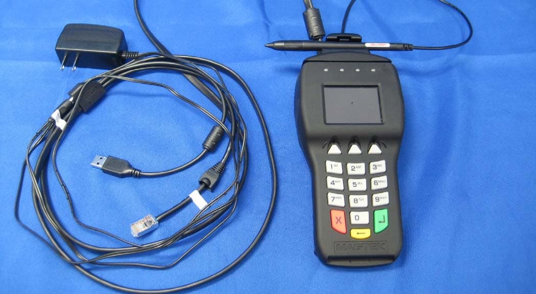
U73-30056017
Aug 20, 2013DynaPro
Equipment Class
DXT - Part 15 Low Power Transceiver, Rx Verified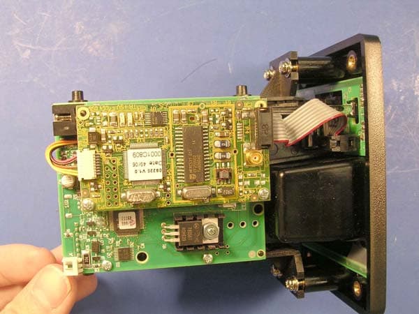
U73-21165046
May 01, 2007Intellistripe 65 Contactless Cad Reader, 21165046
Equipment Class
DXX - Part 15 Low Power Communication Device Transmitter