U9FMO15Wireless Alarm
Kolf Industries (H.K.) Ltd.
Click to zoom
Application Details
- Equipment Class
- DSC - Part 15 Security/Remote Control Transmitter
- Date of Grant
- Nov 08, 2010
- Application Purpose
- Original Equipment
- Date of Application
- Nov 08, 2010
- Equipment Note
- Wireless Alarm
- Frequency Range
- 433.92000000 - 433.92000000
- Company
- Kolf Industries (H.K.) Ltd.
- Country
- Hong Kong
Documents & Files
Document Text
Text extracted from the exhibit documents filed with the FCC. Open a document above to read the original.
Users Manual
IMPORTANT Pleasereadinstruction bookletbefore use Mo delMO15 Contents Instructions for Use ..................................................................................2 Standard Sensor ..........................................................................3 Bed-Mat........................................................................................4 Pressure-Mat ................................................................................5 ..................................................................................6 Resetting RX Sound ....................................................................7 Channel Selection ........................................................................7 Receiver LED Number Selection ..................................................7 Re-tuning (Pairing) ........................................................................7 Sound Selection Switch ..............................................................7 Batteries ......................................................................................8 Guarantee ....................................................................................8 Repairs ........................................................................................9 Cleaning........................................................................................9 Fault finding..................................................................................9 Specification TX & RX .................................................................. 10-11 Diagrams TX & RX ........................................................................13-15 How to Connect TX with Different Sensors ................................16-19 The Inverter ..................................................................................20-21 MM061010 Plastic Clip Wet Sensor Instructions for use 1. Switch on the receiver (Rx) unit. Green LED will flash once every two seconds. 2. Remove insulator from battery compartment (if present) of the transmitter (Tx) unit. 3. Plug the sensor of choice into the transmitter (Tx) unit. 4. If used withSensor: i)Make sure the Sensor lever is in the up position. (Lowering the lever without placing material between the front jaws will a ctivate the transmitter and trigger the receiver buzzer). If buzzer does not sound, retune Tx & Rx as per instructions. ii) Using the safety pin, attach the Tx to the pyjama top or nightdress close to the shoulder. Attach Tx to material before wearing garment if preferable. Carefully lock the safety pin. Do not use safety pin if faulty. Optional shoulder clip is available for clinics on request if sa fety pin use is unsuitable. iii) Thread sensor lead inside top as shown in diagram above For small children, loop and tie sensor lead to shorten length. iv) Attach sensor clip to the outside of close fitting underwear, at the location most likely to get wet first, by inserting the folded underpants material inside the front jaw of the clip then lowering the lever. (Lowering the lever without any dry material in the jaws will activate the Tx, trigger the Rx alarm and prevent the Rx from being reset). Lift the lever and press the reset button. Do not reset the Rx by switching off. Always use the reset button. 2 onto the material by pressing down the lever. IMPORTANT: Sensor in soapy water, rinse and shake dry. IMPORTANT: DO NOT PLACE ANY MATERIAL UNDER THE SECURING LEVER. Place underwear material into mouth Plastic Clip Plastic Clip Plastic Clip Plastic Clip Plastic Clip 3 5. If used with Standard Sensor: a)Absorbent pad: i) Cut off one end of an absorbent pad and insert the sensor in between the layers. ii) Anchor with crocodile clip to prevent sensor from being pulled out. Uncover the backing strip and stick the pad inside a pair of close fitting pants, ensuring the sensor is located where it will come into contact with the flow of urine. b) Between two pairs of un derpants: i)Sandwich between two pairs of cotton briefs (not boxer shorts). Anchor with crocodile clip. c) Within Y-front fold: i)Place sensor plate within Y-fronts fold and anchor by locating the crocodile clip on the outside of the waistband of the pants. Avoid nylon/polyester underwear. d) With pull-ups or nappies: i)Cut a small slit into the outside of the material and insert the sensor plate at a location close to the urine flow. PLEASE NOTE THAT SENSOR & CLIP ARE GOLD PLATED. 4 If using a plastic protective mattress sheet place adhesive tape over the Bed-Mat lower contacts. Use a BATH TOWEL to cover the Bed-Mat and cotton sheet. Adjust towel thickness to suit. Pillow Bedside alarm or other small Malem Alarm. Bedside table Tuck wire from Bed-Mat to alarm away neatly to prevent tripping or entanglement. Tie Bed-Mat around mattress. Place cotton sheet over Bed-Mat. Under NO circumstances should any of the alarms be attached to the users’ clothing when using a Bed-Mat. Holes for tying Bed-Mat to the mattress. Mattress Bet-Mat Sheet Bath Towel Hints The reset button will stop the alarm from sounding only if the Bed-Mat is dry or disconnected. The Bed-Mat positively locks to the alarm to prevent accidental disconnection. However, it must be unlocked before attempting to reset the alarm. Please use a thicker cotton sheet or place a bath towelabove the Bed-Mat if sweating is triggering the alarm prematurely. Avoid plastic and man-made fibres as they may cause static discharge and false alarm. Reduce alarm sensitivity. (See diagram) Treat the Bed-Mat with care. Avoid folding it or jumping over it. Please replace the Bed-Mat with a new one if it has deteriorated and use a new one with each child. Please note that sleeping directly on an uncovered Bed-Mat or touching it by hand may trigger the alarm. Do not place plastic sheets directly under the Bed-Mat as condensation may trigger the alarm. 7.If used with Pressure-Mat Sensor: a) Activation by applied pressure: place the Pressure-Mat (PM) in the appr…
Text truncated - open the document above for the full version.
External Photos
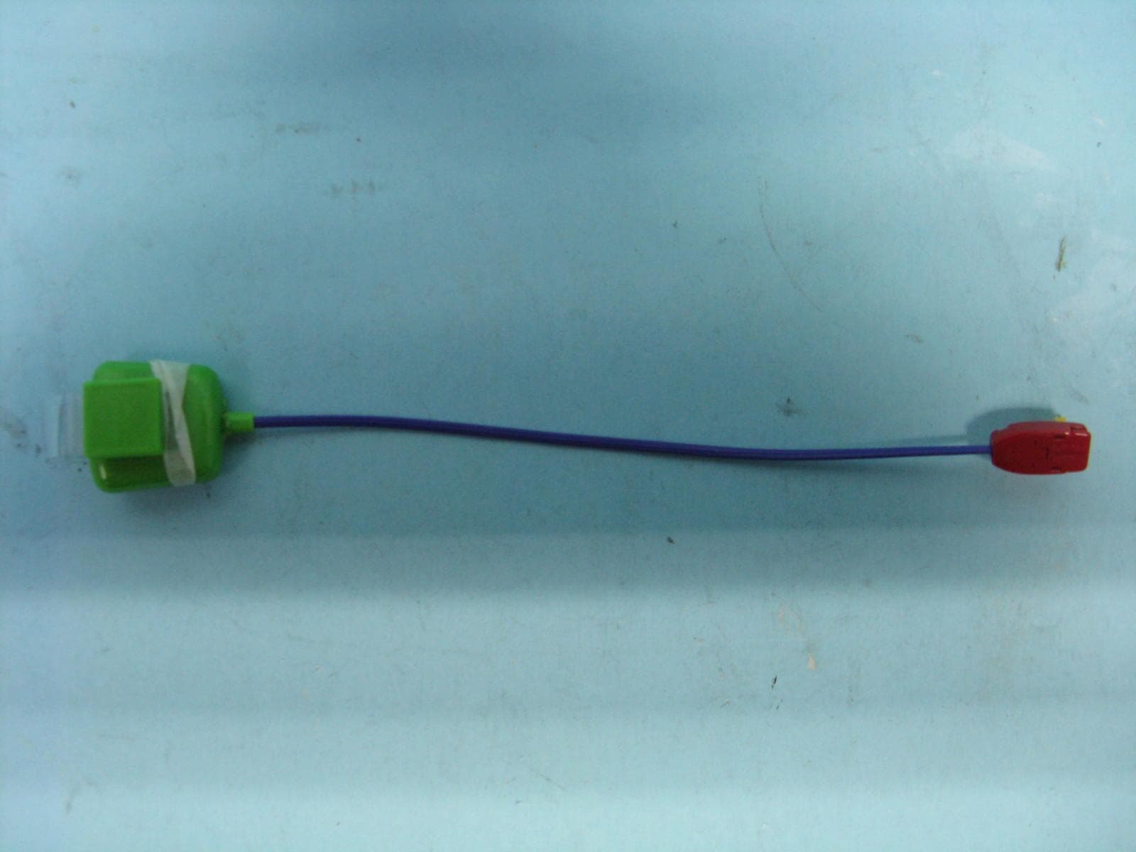
PHOTOGRAPH OF THE PRODUCT FRONT VIEW OF THE PRODUCT PHOTOGRAPH OF THE PRODUCT REAR VIEW OF THE PRODUCT PHOTOGRAPH OF THE PRODUCT PHOTOGRAPH OF THE PRODUCT PHOTOGRAPH OF THE PRODUCT PHOTOGRAPH OF THE PRODUCT
Internal Photos
PHOTOGRAPH OF THE PRODUCT INNER CIRCUIT TOP VIEW PHOTOGRAPH OF THE PRODUCT INNER CIRCUIT BOTTOM VIEW
Operational Description
Circuit Description: Tx The transmitter is powered with a 12V DC battery BATT1. The transmitter control circuit is formed with a push button S1, transmitter. When S1 is pressed, it wakes up the U1, The LED (D3) is flashed as to indicate the transmitter is turned on. Depending on the dip switches SW1 and SW4 setting, U1 is an encoder that encodes the SW1 and SW4 setting into proper format, the encoded signal then is output serially to Q5 (9014D)and Q4 (8550D) This encoded signal then modulated by the modulator that is formed with a SAW resonator X2 (433.92MHz) and a transistor Q3 (2SC3356). The modulated signal is fed into the antenna circuit L1, L2, L3, and radiated out.
Schematics
SHEET 1 OF 1 REVISED BY: 5 Kolf Industries (H.K.) Ltd. 6 5 4 3 2 1 B A B 4 6 REV.: DRAWN BY: PCB NO.: SCH FILE: TITLE: MODEL: DATE: PCB FILE: A 1 2 3 D C C D REVISION HISTORY DATE REV. PCB 001-398301-03 PCB 001-398401-02 KP398 (MO-15) TX-FCC Set Address Set ID Dice direct bond on PCB Patrick Li 08-Oct-2010 KP398-TX-FCC.sch KP398 (MO-15) Battery Low Detector L2 Track on PCB 0 KP39830102B.pcb KP39840101B-FCC.pcb Ground plane, as close as possible TX mode JP1 Open = Continuous JP1 Short = Periodic Patrick Li 08-Oct-2010 Final Released 0 R1 100K R2 100K R3 100K R4 100K R5 100K R6 100K R7 100K R8 100K R9 100K R10 100K R11 100K R12 100K R13 100K 1 PC1 2 PC2 3 PC3 4 PC4 5 PC5 6 PC6 7 PC7 8 OSC2 9 OSC1 10 MCLRB 11 VSS 12 TOCKI 13 VDD 14 VSS 15 PA0 16 PA1 17 PA2 18 PA3 19 PB0 20 PB1 21 PB2 22 PB3 23 PB4 24 VSS 25 PB5 26 PB6 27 PB7 28 PC0 U1 P07 R14 100K C1 0.1uF X1 4MHz C2 20pF C3 20pF S1 R15 100K C4 0.1uF E B C Q1 9015SC R16 1M R17 20K 1% R18 18.2K 1% E B C Q2 9014SC R19 20K 1 3 2 U2 HT-7150A C5 0.1uF C6 0.1uF + C7 10uF X2 433.92Mhz C9 1pF C10 1.5pF E B C Q3 C3356-R25 C11 12pF R20 820R R21 100K E B C Q4 MMBT3906 D1 D2 R22 100K R23 4.7K E B C Q5 MMBT3904 R24 1K C13 0.1uF D3 1 2 3 4 5 S2 FSIP5S 1 2 3 4 5 S3 FSIP5S 1 2 3 4 5 6 7 8 9 10 11 12 13 14 15 16 SW1 8BIT-SW1 + C14 10uF 1 2 3 4 5 6 7 8 9 10 11 12 S4 6BIT-SW R25 330R C15 1uF D4 C8 6pF BATT1 L3 22nH R26 NM R27 100K JP1 L1 100nH R28 10K C12 100pF +5V +5V +12V +5V +12V +12V +5V +12V
Test Report
STC Test Report Date : 2010-09-15 Page 1 of 22 No. : HM165655 The Hong Kong Standards and Testing Centre Ltd. 10 Dai Wang Street, Taipo Industrial Estate, N.T., Hong Kong Tel: (852) 2666 1888 Fax: (852) 2664 4353 Homepage: www.hkstc.org E-mail: [email protected] This report shall not be reproduced unless with prior written approval from the Hong Kong Standards and Testing Centre Ltd. For full text of “Conditions of Issuance of Test Report”, please refer to overleaf or refer to the website of Homepage. Applicant (KOI004): Kolf Industries (H.K.) Ltd. No. 1 2/F., Sing Win Ind. Bldg., 15-17 Shing Yip Street, Kwun Tong, Kowloon Manufacturer: Kolfda Electronic (Shenzhen) Ltd. 6/F, Block 1, Sheung Yuen Ind. Bldg., North Honggang Road Luohu, Shenzhen, China Description of Sample(s): Submitted sample(s) said to be Product: Wireless Alarm Brand Name: Malem Model Number: MO15 FCC ID: U9FMO15 Date Sample(s) Received: 2010-08-23 Date Tested: 2010-08-31 to 2010-09-13 Investigation Requested: Perform ElectroMagnetic Interference measurement in accordance with FCC 47CFR [Codes of Federal Regulations] Part 15: 2009 and ANSI C63.4:2003 for FCC Certification. Conclusion(s): The submitted product COMPLIED with the requirements of Federal Communications Commission [FCC] Rules and Regulations Part 15. The tests were performed in accordance with the standards described above and on Section 2.2 in this Test Report. Remark(s): --- Dr. LEE Kam Chuen Authorized Signatory ElectroMagnetic Compatibility Department For and on behalf of The Hong Kong Standards and Testing Centre Ltd. STC Test Report Date : 2010-09-15 Page 2 of 22 No. : HM165655 The Hong Kong Standards and Testing Centre Ltd. 10 Dai Wang Street, Taipo Industrial Estate, N.T., Hong Kong Tel: (852) 2666 1888 Fax: (852) 2664 4353 Homepage: www.hkstc.org E-mail: [email protected] This report shall not be reproduced unless with prior written approval from The Hong Kong Standards and Testing Centre Ltd. For Conditions of Issuance of this test report, please refer to the overleaf or Homepage CONTENT: Cover Page 1 of 22 Content Page 2-3 of 22 1.0 General Details 1.1 Equipment Under Test [EUT] Page 4 of 22 1.2 Description of EUT operation 1.3 Date of Order Page 4 of 22 1.4 Submitted Sample(s) Page 4 of 22 1.5 Test Duration Page 4 of 22 1.6 Country of Origin Page 4 of 22 2.0 Technical Details 2.1 Investigations Requested Page 5 of 22 2.2 Test Standards and Results Summary Page 5 of 22 3.0 Test Results 3.1 Emission Page 6-9 of 22 3.2 Bandwidth Measurement Page 10-11 of 22 STC Test Report Date : 2010-09-15 Page 3 of 22 No. : HM165655 The Hong Kong Standards and Testing Centre Ltd. 10 Dai Wang Street, Taipo Industrial Estate, N.T., Hong Kong Tel: (852) 2666 1888 Fax: (852) 2664 4353 Homepage: www.hkstc.org E-mail: [email protected] This report shall not be reproduced unless with prior written approval from The Hong Kong Standards and Testing Centre Ltd. For Conditions of Issuance of this test report, please refer to the overleaf or Homepage Appendix A List of Measurement Equipment Page 12 of 22 Appendix B Duty Cycle Correction During 100 msec Page 13-19 of 22 Appendix C Periodic Operation Page 20 of 22 Appendix D Photographs Page 21-22 of 22 STC Test Report Date : 2010-09-15 Page 4 of 22 No. : HM165655 The Hong Kong Standards and Testing Centre Ltd. 10 Dai Wang Street, Taipo Industrial Estate, N.T., Hong Kong Tel: (852) 2666 1888 Fax: (852) 2664 4353 Homepage: www.hkstc.org E-mail: [email protected] This report shall not be reproduced unless with prior written approval from The Hong Kong Standards and Testing Centre Ltd. For Conditions of Issuance of this test report, please refer to the overleaf or Homepage 1.0 General Details 1.1 Equipment Under Test [EUT] Description of Sample Submitted sample(s) said to be Product: Wireless Alarm Manufacturer: Kolfda Electronic (Shenzhen) Ltd. Brand Name: Malem Model Number: MO15 Rating: 12Vd.c. (“EL12” size battery x 1) 1.2 Description of EUT Operation The Equipment Under Test (EUT) is a Kolf Industries (H.K.) Ltd.., Wireless Alarm. When the EUT achieves wet detection, the transmitter will periodically send a signal to the receiver unit [§15.231(e) – periodic operation]. The transmission signal modulation by IC; and the type is ASK modulation. 1.3 Date of Order 2010-08-23 1.4 Submitted Sample(s): 1 Sample 1.5 Test Duration 2010-08-31 to 2010-09-13 1.6 Country of Origin China STC Test Report Date : 2010-09-15 Page 5 of 22 No. : HM165655 The Hong Kong Standards and Testing Centre Ltd. 10 Dai Wang Street, Taipo Industrial Estate, N.T., Hong Kong Tel: (852) 2666 1888 Fax: (852) 2664 4353 Homepage: www.hkstc.org E-mail: [email protected] This report shall not be reproduced unless with prior written approval from The Hong Kong Standards and Testing Centre Ltd. For Conditions of Issuance of this test report, please refer to the overleaf or Homepage 2.0 Technical Details 2.1 Investigations Requested Perform ElectroMagnetic Interference measurement in accordance with FCC 47CFR [Codes of Federal Regulations] Part 15 2009 and ANSI C63.4:2003 for FCC Certification. 2.2 Test Standards and Results Summary Tables EMISSION Results Summary Test Condition Test Requirement Test Method Class / Test Result Severity Pass Failed N/A Field Strength of Fundamental Emissions & Spurious Emissions FCC 47CFR 15.231e ANSI C63.4:2003 N/A Radiated Emissions, 30MHz to 1GHz FCC 47CFR 15.209 ANSI C63.4:2003 N/A Note: N/A - Not Applicable STC Test Report Date : 2010-09-15 Page 6 of 22 No. : HM165655 The Hong Kong Standards and Testing Centre Ltd. 10 Dai Wang Street, Taipo Industrial Estate, N.T., Hong Kong Tel: (852) 2666 1888 Fax: (852) 2664 4353 Homepage: www.hkstc.org E-mail: [email protected] This report shall not be reproduced unless with prior written approval from The Hong Kong Standards and Testing Centre Ltd. For Conditions of Issuance of this test report, please refer to the overleaf or Homepage 3.0 Test Results 3.1 Emission 3.1.1 Radiated Emissions (30 – 1000MHz) …
Text truncated - open the document above for the full version.
Test Setup Photos
PHOTOGRAPH OF THE PRODUCT MEASUREMENT OF RADIATED EMISSION TEST SET UP
Contact Information
Applicant
Stephen Leung(Director)
Test Firm
Hong Kong Standards and Testing CenterWison Wong
Technical Specifications
| # | Rule Parts | Frequency Range | Power Output |
|---|---|---|---|
| 1 | 15.231(e) | 433.92 MHz - 433.92 MHz | - |
Other Applications from Kolf Industries (H.K.) Ltd.
U9FMO12
Feb 01, 2010Wireless Alarm
Equipment Class
DSC - Part 15 Security/Remote Control Transmitter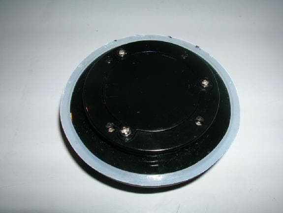
U9FREM40
Jul 23, 2007RF Remote
Equipment Class
DSC - Part 15 Security/Remote Control Transmitter