U9YAL4512Wireless USB 4-port Hub
Alereon, Inc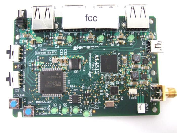
Click to zoom
Application Details
- Equipment Class
- UWB - Ultra Wideband Transmitter
- Date of Grant
- Jun 26, 2007
- Application Purpose
- Original Equipment
- Date of Application
- May 15, 2007
- Equipment Note
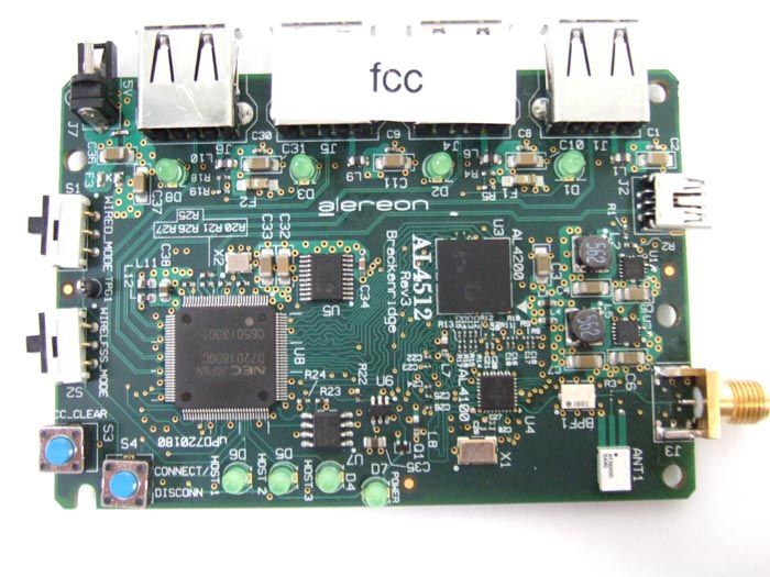
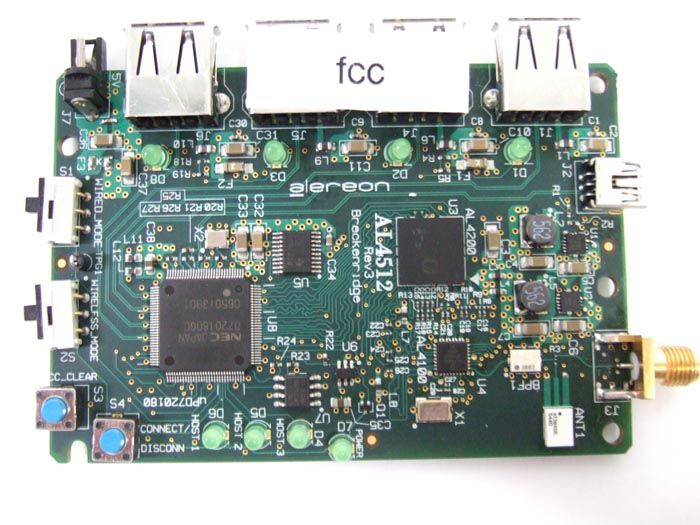
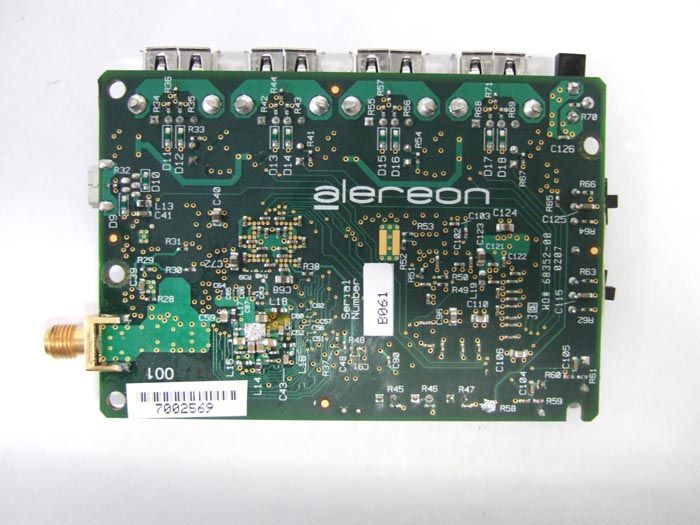
- Wireless USB 4-port Hub
- Frequency Range
- 3100.00000000 - 4800.00000000
- Company
- Alereon, Inc
- Country
- United States
Documents & Files
Document Text
Text extracted from the exhibit documents filed with the FCC. Open a document above to read the original.
Users Manual
Draft Rev. 0.1 May 3, 2007 Alereon Confidential AL4512 Hub User Guide Draft Version 0.1 Document Overview This document describes the Alereon AL4512 UWB Hub. 1.0WIRELESS USB/ULTRA-WIDEBAND OVERVIEW The AL4512 Hub allows Ultra-wideband (UWB) wireless data transfer and interoperability with other Certified Wireless USB devices. Certified Wireless USB is the new wireless extension to USB, combining the speed and security of wired USB technology with the connivance and ease-of-use of wireless. Certified Wireless USB supports robust high-speed wireless connectivity by utilizing the common WiMedia UWB radio platform developed by the WiMedia Alliance. UWB technology offers a solution for high bandwidth, low cost, and low power consumption. Certified Wireless USB is the first high-speed wireless personal interconnect technology to meet the needs of multimedia consumer electronics, PC peripherals, and mobile devices. Certified Wireless USB preserves the functionality of wired USB while eliminating the tangle of cable connections. 2.0PACKAGE CONTENTS Your AL4512 Hub Solution package should contain all the items shown in Figure 1. In addition, there will be a CD containing all software (including drivers) and documentation for the AL4512 Hub. See Ta b l e 1 for package contents. Figure 1. AL4512 Hub and Accessories 1 2 3 4 5 Draft 2Alereon ConfidentialRev. 0.1 User’s GuideAL4512 Hub 3.0PRODUCT FEATURES The AL4512 Hub provides numerous features: •Certified Wireless USB offers guaranteed interoperability with other Certified Wireless USB devices. •Eliminates networking cable clutter. •Windows XP compatibility via included software drivers. •Compact designs help prevent desk clutter. •Full one year warranty (see enclosed warranty sheet for details). •55 Mbps–480 Mbps data rates, depending on range, application, and ambient wireless conditions. 4.0SYSTEM REQUIREMENTS The following specifications are necessary for each computer using the AL4512 Hub Solution: •USB-equipped PC •Windows XP with Service Pack 2 and the .NET Framework 2.0 installed* •1GHz (or greater) processor •256MB (or more) memory •At least 50MB of free hard-drive space •At least one other Certified Wireless USB device with which to communicate *Note: Drivers for Windows Vista have not yet been released, but will be before the end of 2007. 5.0RANGE In normal home and business environments, Alereon recommends that the AL4512 hub be placed within 10 meters of the Certified Wireless USB devices with which it is communicating for best operations. Under ideal circumstances and with properly configured Certified Wireless USB devices (such as the AL4504 USB dongle), the AL4512 Hub is capable of significantly longer ranges, but these are not guaranteed. Likewise, in environments with heavy EMF shielding or significant radio frequency (RF) noise, the hub and other Certified Wireless USB devices may need to be placed closer together for optimal performance. 6.0SETUP Perform the following steps to get your AL4512 Hub up and running: 1. Remove all items from the packaging and inspect them for damage. If any appear to have been damaged in shipping, please contact Alereon Technical Support via this web form: http://www.alereon.com/contact-us/ Table 1 AL4512 Hub Package Contents 1AL4512 Certified Wireless USB Hub 2Antenna 3Power Supply 4Power Cord 5USB Cable 6Documentation/Software CD (not shown) Draft Rev. 0.1Alereon Confidential3 AL4512 HubUser’s Guide 2. Put the Documentation/Software CD into the PC to which you wish to attach the Hub. An install program will automatically start running after insertion (if not, please double-click on the program icon on the CD, or reset your permissions to allow the program to run). 3. Follow the on-screen instructions to install the driver and software for the hub. 4. Attach the hub to the PC by plugging it into the USB port. 5. Attach the included antenna to the AL4512 by screwing it into the antenna connector on the side of the hub. Warning: Operation of this unit is authorized by the FCC only with the antenna furnished. Substitution or alteration of the antenna or its connection may void the users authority of operate this device. 6. Following the remaining interactive software instructions to configure the hub for operation. 7. Once you have finished these steps, your AL4512 Hub should be working. 7.0OPERATIONS For details on how to use the Certified Wireless USB software, please see the Alereon Software Guide. 8.0FCC COMPLIANCE 8.1Compliance Statement The following compliance statement applies to the AL4512 Hub: This device complies with part 15 of the FCC Rules. Operation is subject to the following two conditions: (1) this device may not cause harmful interference, and (2) this device must accept any interference received, including interference that may cause undesired operation. 8.2FCC Requirements 8.2.1Modification Voids Compliance Warning Warning: Changes or modifications to the AL4512 Hub not expressly approved by Alereon can void the your warranty and place the AL4512 Hub outside FCC equipment authorization. 8.2.2Electromagnetic Interference Control Electromagnetic Interference (EMI) is any signal or emission, radiated in free space or conducted along power or signal leads, which endangers the function of radio navigation or other safety service (the telephone and cellphones are considered to be safety services) or seriously degrades, obstructs or repeatedly interrupts a licensed radio communications service. Radio communications services include but are not limited to: AM/FM commercial broadcast, television, cellular services, radar, air traffic control, pager and personal communications services (PCS). These licensed services, along with unintentional radiators such as digital devices, including computer systems, contribute to the electromagnetic environment. Electromagnetic Compatibility (EMC) is the ability of items of electronic equipment to function properly together in the electromagnetic environ…
Text truncated - open the document above for the full version.
Cover Letter(s)
Tuesday, May 01, 2007.max
Cover Letter(s)
Tuesday, May 01, 2007 (2).max Tuesday, May 01, 2007 (2).max
Cover Letter(s)
Tuesday, May 01, 2007 (3).max
ID Label/Location Info
Alereon, Inc. AL4512-EVB S/N: W500 FCC ID: U9YAL4512
ID Label/Location Info
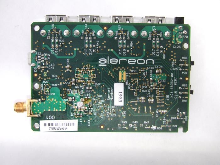
Alereon AL4512 Label Placement Bottom view of PCBA showing label placement
Operational Description
Alereon Confidential Page 1 5/1/2007 Theory of operation; Alereon AL4512 USB 4-Port Hub. The Alereon AL4504 incorporates the functionality of a UWB radio device and a 4-Port USB Hub. This device is intended to provide a short-range wireless USB connection to computers for up to four peripheral units equipped with a USB 2.0 interface. The AL4512 is powered by a +5 Volt power unit which operates from the commercial A.C. power mains. The AL4512 operates in the frequency band defined in the FCC Rules and Regulations for UWB devices. Specifically, it operates between the frequencies of 3.168 and 4.752 GHz per the industry-defined WiMedia 1.1 specification. The AL4512 is comprised of three integrated circuit devices and supporting circuitry for filtering, interface and power conditioning. The AL4512 employs an antenna external to the device which attaches to the device by a Reverse-Polarity SMA connector complying with the requirements of 47 CFR 15.212(a)(iv). The schematic diagram shows a connector, Murata type MM8430, in the RF path on the printed wiring board. This is a production test connector, it is not accessible from outside of the unit housing. Following the antenna is a bandpass filter with a passband from 3.1 GHz to 4.752 GHz which provides suppression of unwanted transmitter emissions and receiver interference rejection in the 2.4 GHz and 5.1 GHz bands. The AL4100 RF Transceiver generates the system reference frequency from a 33 MHz crystal resonator. The 33 MHz reference frequency is multiplied to 4.224 GHz internally within the AL4100 by a PLL multiplier. From this frequency the three band frequencies, 3.432 GHz, 3.960 GHz and 4,488 GHz for both transmit and receive modes are derived internally within the AL4100 by direct synthesis. In addition to the band frequencies, a 1056 MHz clock for ADCs and DACs within the AL4200 Baseband Processor is generated. The interface between the AL4100 RF Transceiver and the AL4200 Baseband Processor consists of the analog RX-I and –Q signals and the analog TX–I and –Q signals all of which are baseband, having 2 MHz to 264 MHz frequency band. The interface also includes a 1056 MHz clock signal and CMOS logic-level control signals which determine the band frequency and TX/RX mode. The interface between the AL4200 Baseband Processor and the UPD720180 MAC device is the industry-defined MPI consisting of CMOS logic-level: 8 data bits, control signals and a 66 MHz clock signal. The UPD720180 MAC implements five external USB 2.0 interfaces: 1. A host interface. This interface is used for association of the wireless USB hub and the host P.C. for wireless link security. This interface is connected only during initial association and in normal wireless 4-Port Hub operation is unconnected. 2. Four USB 2.0 device ports which connect peripheral devices. References. MultiBand OFDM Physical Layer Specification 1.1. WiMedia MAC-PHY Interface Specification 1.0. Universal Serial Buss Specification 2.0.
Test Report
All services undertaken are subject to the following general policy. Reports are submitted for exclusive use of the client to whom they are addressed. Their significance is subject to the adequacy and representative character of the samples and to the comprehensiveness of the tests, examinations or surveys made. This report shall not be reproduced except in full, without written consent of TDK R&D Corporation. This report must not be used to claim product endorsement by A2LA, NVLAP nor any other agency of the US Government. Compliance Report of Alereon AL4512 Module Customer: Alereon, Inc. Date: May 14, 2007 TDK Report: TTS-TR-T112-004 Test performed by: TDK R&D Corporation 1101 Cypress Creek Rd Cedar Park, TX 78613 Technician Checked by Radiated 30 MHz to 40 GHz A. Medina K. Yata Report A. Medina P. Carson This document contains confidential information and cannot be disclosed outside of Alereon or any affiliated company in whole or in part without the express written permission of TDK R&D Corporation. TTS-TR-T112-004 page 2 of 51 1. Executive Summary An EMC evaluation to determine compliance of the Alereon AL4512 UWB Module with requirements of FCC 47 CFR Part 15, Subpart F Section 15.519 was conducted. All references are to the most current version of the Code of Federal Regulations 47 that are currently in effect. In accordance with §2.1033, the following data is presented in support of the Certification of the Modular Wireless USB Hub. The client should retain a copy of this document on file for at least 5 years after the manufacturing of the product has been discontinued. Test Description FCC 47 CFR Section Compliance Operational Limitations 15.519(a) The client has been notified of these limitations. In normal operating mode the transmitter will only send data when associated with a receiver. See section 5 for detail UWB Bandwidth 15.519(b) Yes Radiated Emissions 15.519(c), 15.209 Yes Radiated Emissions in GPS Bands 15.519(d) Yes Peak Emissions within a 50 MHz Bandwidth 15.519(e) Yes Labelling Requirements 15.19/15.212 Yes Report prepared by Approved by Armando Medina Kunio Yata May 14, 2007 May 16, 2007 Page 3 of 51 2. Task Description 2.1. Scope Reference FCC ET Docket No. 98-153, FCC 02-48 First R&O; FCC 47 CFR, Part 15, Subpart A; FCC 47 CFR, Part 15, Subpart B; FCC 47 CFR, Part 15, Subpart C; FCC 47 CFR, Part 15, Subpart F FCC ET Docket No. 04-352, Petition for Waiver of the Part 15 UWB Regulations Filed by MBOA-SIG (Adopted: March 10, 2005) FCC Second R&O 07-56A1 Part 15 unlicensed modular transmitter approval 47 CFR 15.212 Title Revision of Part 15 of the Commission’s Rules Regarding Ultra-Wideband Transmissions Systems; Code of Federal Regulations, Part 15 Subpart A: General Code of Federal Regulations, Part 15 Subpart B: Unintentional Radiators Code of Federal Regulations, Part 15 Subpart C: Intentional Radiators Code of Federal Regulations, Part 15 Subpart F: Ultra-Wideband Operation Purpose of Test To gain FCC Certification for technical requirements for UWB Modular Systems operating between 3.1 GHz and 10.6 GHz. Test Procedures The tests were conducted in accordance with the following documents: FCC ET Docket 98-153, FCC 02-48 First R&O, FCC 07-56A1 ANSI C63.4: 2003: Methods of Measurement of Radio-Noise Emissions from Low-Voltage Electrical and Electronic Equipment in the Range of 9 kHz to 40 GHz FCC Code of Federal Regulations 47, Part 15 Subpart A: General FCC ET Docket No. 04-352, Petition for Waiver of the Part 15 UWB Regulations Filed by MBOA-SIG (Adopted: March 10, 2005) General Procedures FCC Code of Federal Regulations 47, Part 2 Frequency Allocations and Radio Treaty Matter: General Rules and Regulations Classification of EUT Indoor Ultra-Wideband Module Page 4 of 51 2.2. Related Submittal(s)/Grant(s) As required in 07-56A1 and 15.212 a cover letter requesting modular approval is included in the application for equipment authorization. 2.3. Test Plan Reference Publication Year Title FCC 47 CFR, Part 15, Subpart A 10/2004 Code of Federal Regulations, Part 15 Subpart A: General FCC 47 CFR, Part 15, Subpart B 10/2004 Code of Federal Regulations, Part 15 Subpart B: Unintentional Radiators FCC 47 CFR, Part 15, Subpart C 10/2004 Code of Federal Regulations, Part 15 Subpart C: Intentional Radiators FCC 47 CFR, Part 15, Subpart F 10/2004 Code of Federal Regulations, Part 15 Subpart F: Ultra-Wideband Operation FCC ET Docket 98-153, FCC 02-48 First R&O 04/2002 Revision of Part 15 of the Commission’s Rules Regarding Ultra- Wideband Transmissions Systems: First Report & Order ANSI C63.4 01/2004 Methods of Measurement of Radio- Noise Emissions from Low-Voltage Electrical and Electronic Equipment in the Range of 9 kHz to 40 GHz FCC ET Docket No. 04- 352 3/2005 Petition for Waiver of the Part 15 UWB Regulations Filed by MBOA-SIG FCC 47 CFR, Part 15, Subpart C 04/2007 Part 15.212 unlicensed Modular Transmitter Approval 2.4. Client Information APPLICANT Name: Alereon Inc. Address: 7600 North Capital Of Texas Highway Bldg C Suite 200 Austin, TX 78731 Contact Person: David M. Dickson MANUFACTURER Name: Alereon Inc. Address: 7600 North Capital Of Texas Highway Bldg C Suite 200 Austin TX 78731 Contact Person: David M. Dickson Page 5 of 51 2.5. Equipment Under Test (EUT) The following information (with the exception of the date information) has been supplied by the applicant. The test results in this report pertain only to the item tested. General Brand Name Alereon Product Name UWB Module Model Name or Number AL4512 Serial Number Fcc Type of Equipment Wireless USB 4-port Hub Input Power Supply Type External Power Adapter Classification Indoor Ultra-Wideband module system Technical Power Supply Requirements 100-240V ~.5A, 50-60Hz -> 5V DC, 2.5A RF Output Rating -42 dBm EIRP @ 3 meters Operating Frequency Range 3100 MHz to 4800 MHz RF Output Impedance 50 Ω Channel Spacing N/A Pulse Width N/A Pulse Repetition Frequency N/A 10 dB Bandwidth >500 MHz Modulation/Constellation Multiband …
Text truncated - open the document above for the full version.
Contact Information
Applicant
Parmveer Singh(Director of Systems Applications)
Technical Contact
TDK RF SolutionsArmando Medina
[email protected]512-258-9478
1101 Cypress Creek Rd · Cedar Park, Texas · United States
Non-Technical Contact
TDK RF SolutionsPat Carson
[email protected]209-351-1584
Test Firm
TDK RF Solutions, Inc.Robert Sutton
Technical Specifications
| # | Rule Parts | Frequency Range | Power Output |
|---|---|---|---|
| 1 | 15F | 3.10 GHz - 4.80 GHz | - |
Other Applications from Alereon, Inc
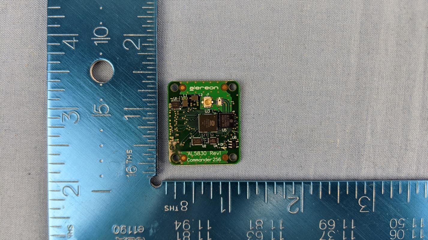
U9YAL5830
Apr 19, 2021UWB Parallel Interface Module (SBU & SAB)
Equipment Class
UWB - Ultra Wideband Transmitter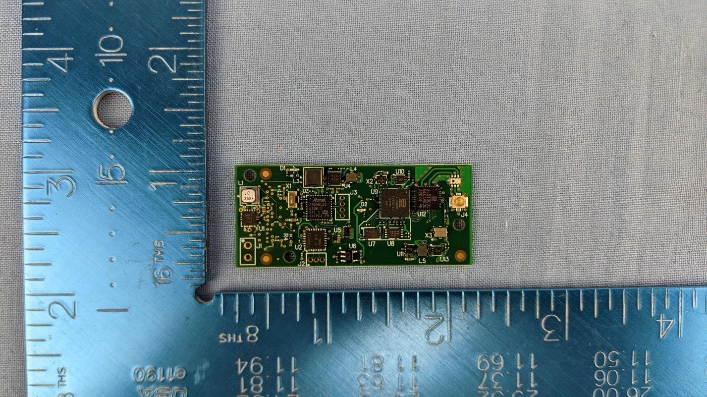
U9YAL5835
Apr 19, 2021UWB Serial Interface Module (SBU & SAB)
Equipment Class
UWB - Ultra Wideband Transmitter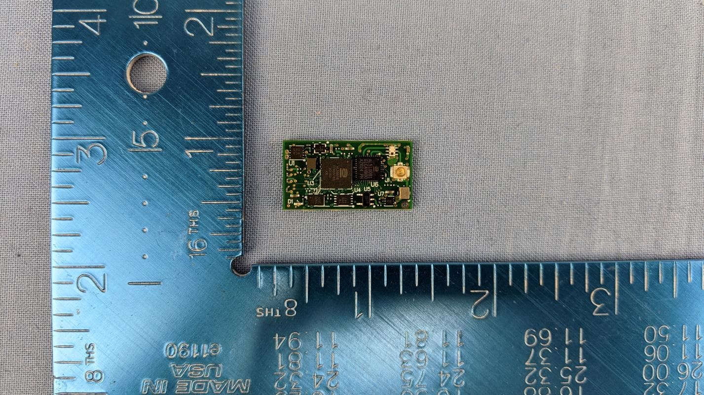
U9YAL5808
Apr 13, 2021UWB Octal SPI Module (SBU & SAB)
Equipment Class
UWB - Ultra Wideband Transmitter
U9YAL5833
Apr 13, 2021UWB Parallel Interface Module (SBU & SAB)
Equipment Class
UWB - Ultra Wideband Transmitter
U9YHS6618A
Aug 26, 2012Wireless USB Dongle
Equipment Class
UWB - Ultra Wideband Transmitter