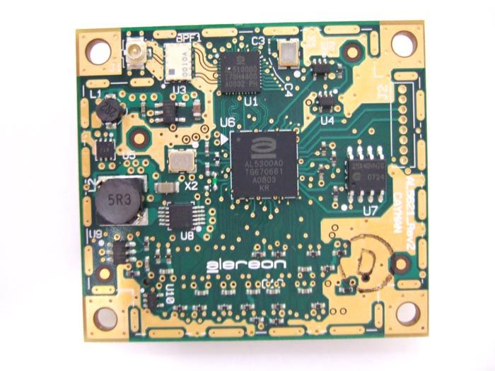
U9YAL5621AL5621 PCB RADIO MODULE
Alereon, Inc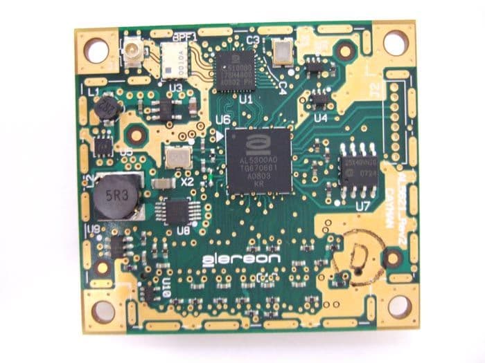
Click to zoom
Application Details
- Equipment Class
- UWB - Ultra Wideband Transmitter
- Date of Grant
- Sep 02, 2008
- Application Purpose
- Original Equipment
- Date of Application
- Jun 08, 2008
- Equipment Note
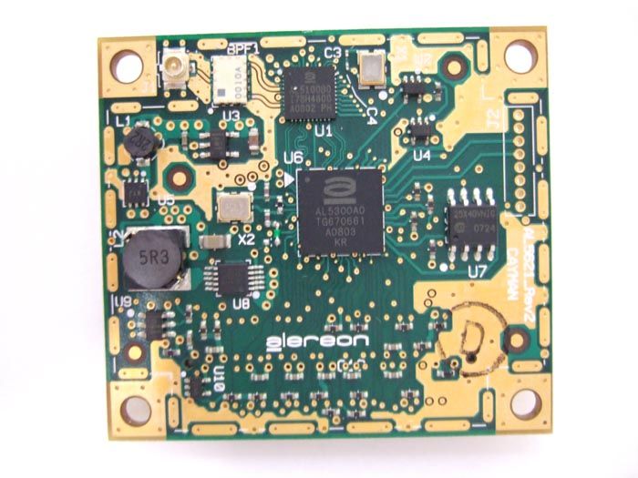
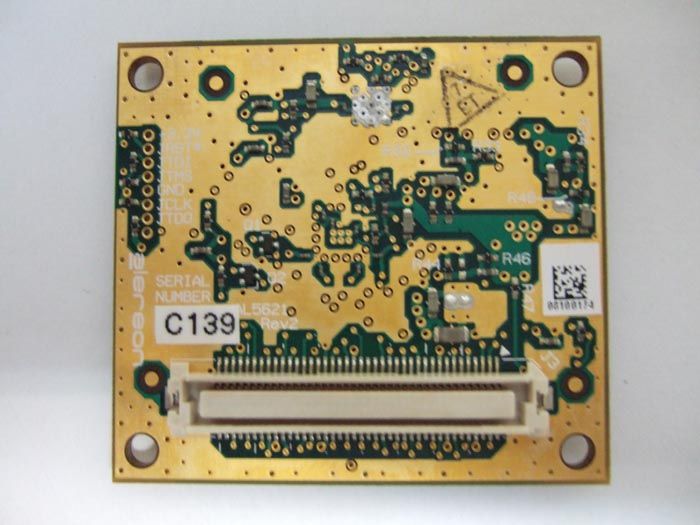
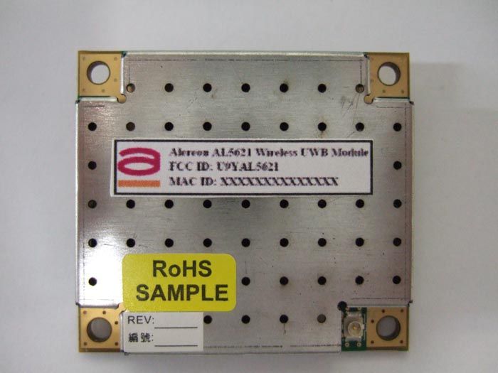
- AL5621 PCB RADIO MODULE
- Frequency Range
- 7392.00000000 - 8976.00000000
- Company
- Alereon, Inc
- Country
- United States
Documents & Files
Document Text
Text extracted from the exhibit documents filed with the FCC. Open a document above to read the original.
Users Manual
Rev. 2.0 – Mar 2008Confidential Release Under Alereon NDA USER GUIDE INTRODUCTION The AL5621 PCB Radio module is a complete compact device radio reference design that enables quick design of UWB enabled products. The AL5621 combines the Alereon AL5000 chipset along with on board power supplies, an antenna output, and three different system interfaces. 1.0REFERENCE DESIGN FEATURES Q Optimized Performance with AL5100 (3.1GHz to 10.6GHz) All Worldwide Bands. Q Complete Baseband Processor (BBP) and Media Access Controller (MAC) Q High Precision Data Path and Data Converters allowing reliable link at extended ranges Q Fully Integrated MAC Protocol Engine Supports All Industry Standards WiMedia Protocols — Certified Wireless USB — WiMedia Link Layer Protocol — Bluetooth 3.0 (supported by future SW releases) Q Industry Standard Interfaces — ULPI 1.1 Interface: 8-Bit / 12 Pins for USB 2.0 PHYs — CF+ 3.0 / Generic Parallel Interface: 8 & 16-Bits — SDIO 1.1 Interface 1-Bit and 4-Bit Modes — UART interface for Cable Associate function Q Operates from a single (+3.3 V, regulated) supply Q Small Form Factor (38.46 x 27.18 mm) (1.5 x 1 in) Q 3 GPIO lines for LEDs or additional control signals Figure 1.AL5621 Worldwide Radio Card AL5621 Rev 2 Worldwide Wireless USB Device Radio Card Evaluation Board User Guide AL5621 Rev 2 Worldwide Wireless USB Device Radio Card Evaluation Board User GuideUser Guide 2Rev. 2.0 Figure 2.Design Overview - Top Side Figure 3.Design Overview - Bottom Side B U4 J2 R6 R7 R16 C16 R24 R22 U6 R12 C14 C15 R23 C12 BPF1 U3 X2 R2 C7 C9 R11 R19R17 C11 J1 C1 R9 R1 U7 U2 R5 R4 R14 R15 X1 C3 C4 R13 C13 R3 R21 U1 R20 C2 U8 C6 R18 C10 R10 U10 C8 C5 L2 U9 R8 L1 U5 SHLD1 B R29 R37 R28 C35 Q2 R25 C26 J3 R31 C20 R30 R40 C23 C36 R27 C21 R45 C41 R26 R32 C29 C30 C39 C42 R33 R47 R34 R48 R35 R36 R38 R39 Q1 C18 C17 C37 C19 C24 C25 C28 C27 C38 R42 L3 R41 C22 C31 C40 R43 R44 C43 R46 C32 C44 C33 R49 C34 User GuideAL5621 Rev 2 Worldwide Wireless USB Device Radio Card Evaluation Board User Guide Rev. 2.03 2.0BLOCK DIAGRAM Figure 4.AL5621 Block Diagram 3.0USER I/O INTERFACE HEADERS ULPI / SDIO / CF+ (BASE MOTHERBOARD CONNECTIONS) AL5300 BBP/MAC AL5100 RF Transceiver BDF U.FL A p p l i c a t i o n I n t e r f a c e Host Interface Connectors (+3.3 V) (Control) (ULPI) (SDIO) (CF+) (GPIO) (Reset) Control Signals Flash Memory +1.2 V +3.3 V +2.4 V Power up Reset Reset GPIO 20 MHz44 MHz AL5621 Rev 2 Worldwide Wireless USB Device Radio Card Evaluation Board User GuideUser Guide 4Rev. 2.0 4.0DESIGN CONSIDERATIONS 4.1Power One +3.3 V power supply at max data rate average current of 500 mA with peak at 750 mA. 4.2Board Reset During power up, an "on board" power monitor holds the board Reset for approximately 150 ms. The card can also be reset at any time by asserting the "Card_Reset#" signal low. It is also important to note that the Mode Pins HSTIF_SEL_0 & HSTIF_SEL_1 are sampled on the rising edge of Card_Reset#. 4.3Mode Switching During Power-Up, the HSTIF_SEL pins are sampled to configure the AL5300 HSTIF pins to one of three different host interface operating modes. The HSTIF_SEL pins must remain static for the duration of the operation of the AL5300 BBP/MAC. Table 1 shows the proper settings of the HSTIF_SEL pins. 4.4Firmware Boot-Up After completing the power-up cycle and after Card_Reset# is de-asserted, the AL5300 BBP/MAC automatically loads the Executable and Linking Format (ELF) firmware image into the chip’s internal instruction memory. There are two boot modes, SPI and HOST. When utilizing SPI boot mode, the ELF image is loaded from an external EEPROM, which is connected to the AL5300 BBP/MAC using an industry standard 4-wire SPI port. When utilizing HOST boot mode, the ELF image is loaded directly over the HSTIF through either CF+, SDIO, or ULPI, and eliminates the need for an external EEPROM. Once the ELF image has been loaded, the AL5300 BBP/MAC will provide a software handshake to the Alereon software drivers indicating that the AL5300 BBP/MAC is ready for normal operation. The state of the HOST_BOOT pin determines which of two modes is used (refer to Ta b l e 2). 5.0CF+ SIGNAL DEFINITIONS The CF+/General Purpose Parallel interface can be configured as either a 8-bit or 16-bit parallel data port. The AL5300 BBP/MAC utilities a FIFO memory buffer at the interface, allowing for simple and efficient high throughput data transfers without affecting the operation of the wireless link. The CF+/General Purpose Parallel interface can be configured and used in accordance to the CF+ specification (CompactFlash, Revision 3.0). When used as a CF+ port, the interface is compatible to both the I/O and Memory modes of operation. The features of the AL5300 BBP/MAC CF+/General Purpose Parallel interface include: •Interrupt-driven interface (the AL5300 BBP/MAC will interrupt the host system) •10 registers used to distinguish data and control spaces •Payload data is ordered by a FIFO and is pushed or pulled through a single address •Data and control registers can be accessed either as a 8-bit or 16-bit data word Table 3 provides a listing of the CF+ interface pins and their functions. Table 1.HSTIF_SEL Pin Settings Host Interface ModeHSTIF_SEL[1:0]* CF+/ Generic Parallel00 SDIO01 ULPI10 Reserved11 *Note: Please connect the HSTIF_SEL pins to GND for a “0” or do not connect them for a “1”. Both HSTIF_SEL signals are pulled high on the daughter board through a 10K resistor to VDD. 0 = GND; 1 = No-Connect. Table 2.Boot Modes Boot ModeHOST_BOOT* SPI Boot Mode0 Host Boot Mode1 *Note:Please connect HOST_BOOT through a 330 Ω resistor to GND for “0” or No- Connect for “1”. 0 = 330 Ω to GND; 1 = No-Connect. User GuideAL5621 Rev 2 Worldwide Wireless USB Device Radio Card Evaluation Board User Guide Rev. 2.05 Table 3.CF+/General Purpose Parallel Interface Pin Descriptions AL5300 PinNameTypeDescription P8, P7, P6, P5, L5, P4, N4, N3, P1, N1, L2 ADDR[10:0]Input Memory Mode: These address lines along with the CF_REG# signal are use…
Text truncated - open the document above for the full version.
Cover Letter(s)
[7600 N. Capital of Texas Hwy] [Building C] [Suite 200] [Austin, TX 78731] ph [512-345-4200] fx [512-345-4201] June 6, 2008 Chief, Authorizations Branch Federal Communications Commission 7435 Oakland Mills Road Columbia, MD 21046 Re: Alereon Application for Certification of Singular Modular Transmitter FCC ID: U9YAL5621 To Whom It May Concern: Please be advised that the following exhibits are to be held confidential on behalf of Alereon: Schematics Block Diagrams Bill of Materials Additionally, Alereon requests short-term confidentiality for the following exhibits. Internal and external photographs This application contains technical information that Alereon considers to be trade secrets and proprietary. If made public, the information might be used to the disadvantage of the applicant in the market place. David Dickson Senior Principal RF Engineer Alereon, Inc.
Cover Letter(s)
[7600 N. Capital of Texas Hwy] [Building C] [Suite 200] [Austin, TX 78731] ph [512-345-4200] fx [512-345-4201] p.1/2 June 6, 2008 Chief, Authorizations Branch Federal Communications Commission 7435 Oakland Mills Road Columbia, MD 21046 Subject: Request for unlicensed Modular Transmitter Approval. Reference: FCC 07-56A1 47 CFR 15.212 To Whom It May Concern: Alereon, Inc. hereby requests FCC Equipment Authorization as a Singular Modular Transmitter of the Alereon, Inc. Model AL5621 UWB Module, FCC ID: U9YAL5621. Alereon, Inc. intends to manufacture this device and market it as a computer modular component. This letter addresses the information required by points one through eight of 47 CFR 15.212. 1. The modular transmitter must have its own RF shielding. Shielding necessary for normal operation is accomplished by a metal shield enclosure which attaches to the printed wiring board and encloses the RF circuitry, including the frequency-determining element. 2. The modular transmitter must have buffered modulation/data inputs. The Alereon AL5621 receives data via one of two selectable industry-standard interfaces; a 16-bit parallel data interface based on the CF+ standard or an industry-defined ULPI interface. The interface is selected by a pin strapping option in the host system and is not user- selectable. Either of these digital interfaces limit the data rate and modulation. 3. The modular transmitter must have its own power supply regulation. The Alereon AL5621 receives power from the host system. The +3.3 Volt source from the host system is filtered on the module to power a +3.3V domain and regulated on the module to produce the main +1.2V digital subsystem domain. The +3.3V domain is also regulated on the module to produce two additional power domains required by the module circuitry; +2.4V and +1.2V. The power regulation topology may be seen on sheet nine of the schematic diagram included in the filing for FCC Equipment Authorization. 4. The modular transmitter antenna must comply with the antenna and transmission system requirements of sections 15.203, 15.204(b) and 15.204(c). The antenna of the Alereon AL5621 UWB Module is an external monopole which attaches to the AL5612 by a 60mm coaxial cable with a type U.FL connector. The antenna is intended to be permanently attached to the product housing and the connector is not accessible to the user. The connector complies with the requirement of FCC 15.203 for a unique coupling. [7600 N. Capital of Texas Hwy] [Building C] [Suite 200] [Austin, TX 78731] ph [512-345-4200] fx [512-345-4201] p.2/2 The antenna is an Alereon design that is based on the Omron WXA-N1SF SMD UWB antenna. 5. The modular transmitter must be tested in a stand-alone configuration. As described in section 2.6.3 of the test report included in the filing for FCC Equipment Authorization, the AL5621 UWB Module plus antenna was tested without a housing. For the tests reported the module was attached to an Alereon designed test environment which provided power and a USB interface to the controlling computer. 6. The modular transmitter must be equipped with either a permanently affixed label or must be capable of electronically displaying its FCC identification number. The Alereon AL5621 is intended to be placed within the host system enclosure unique to the brand I.D. of the host system. The prescribed label with the FCC Identifier will be applied to the outside of the host system housing. Additionally, the module will have a label affixed which includes the FCC identifier. An example of the label which will be used is included in the filing for FCC Equipment Authorization. 7. The modular transmitter must comply with any specific rule or operating requirements applicable to the transmitter. Part 15.519 of the FCC rules and Regulations requires that a UWB transmitter shall transmit only when it is sending information to an associated receiver. That rules part also requires that the UWB intentional radiator shall cease transmission within 10 seconds unless it receives an acknowledgement from the associated receiver that its transmission is being received. An acknowledgment of reception must continue to be received by the UWB intentional radiator at least every 10 seconds or the UWB device must cease transmitting. This requirement is met by design and is implemented by the firmware encoded into the device. 8. The modular transmitter must comply with any applicable RF exposure requirements in its final configuration. There are no RF exposure requirements for UWB devices operating under subpart F of the FCC Rules and Regulations. David M. Dickson Sr. Principal Engineer Alereon, Inc.
Cover Letter(s)
[7600 N. Capital of Texas Hwy] [Building C] [Suite 200] [Austin, TX 78731] ph [512-345-4200] fx [512-345-4201] June 6, 2008 Chief, Authorizations Branch Federal Communications Commission 7435 Oakland Mills Road Columbia, MD 21046 To Whom It May Concern: Please be advised that Alereon, Inc. authorizes TDK RF Solutions to act on our behalf, until otherwise notified, for applications submitted to the Federal Communications Commission (FCC) regarding Ultra-Wideband (UWB) products. We certify that we are not subject to denial of federal benefits, that includes FCC benefits, pursuant to Section 5301 of the Anti-Drug Abuse ACT of 1988, U.S.C. 862. Further, no party, as defined in 47 CFR 1.2002(b), to the application is subject to denial of federal benefits, that includes FCC benefits. David Dickson Senior Principal RF Engineer Alereon, Inc.
Operational Description
Confidential (AC)-080425-TW ,Alereon, April. 25 ,2008, – P1 SMD Antenna Type: WXA-N1SF Technical data No. I tem P age 1 D i m ension/Terminal arra y/ Recom m ended land pattern. 2 2 E valuation Board Condition. 3 3 VSWR Measuremen t D a ta. 4 4 R adiation Pattern Measurement Data. 5-6 NOTESThe informati o n c o nt a i n in this d o cument is confidential . Please do no t present to an yone outside of your company. All measurements repres ented h a ve been made in idea l circum s t ances and without w a r r anties. Real-world situations are l e ss than ideal circum stan ces and performances vary a c c o rding to the de si gn as well as the us e of the product in environment it is used in. Confidential (AC)-080425-TW ,Alereon, April. 25 ,2008, – P2 1. Dimension/Ter m inal Array/Recommended Land Pattern Dime ns ion ( in mm) Terminal array Recommended land pattern NOTE . T O L ERANCE ± 0.3 m m T YPE LOT No. HOLDING T E RMINAL HOLDING T E RMINAL FEEDING T E R M INAL T E RMINAL N O. ( T OP VIE W ) Recomme nde d land pattern SCALE 3:1 T O LERANCE ± 0.05 Confidential (AC)-080425-TW ,Alereon, April. 25 ,2008, – P3 2. Evaluation Board Condition. Dimensions of to p si de (Board and land dimension s ) ( in mm) (No GND on bottom side) Appearan ce (photo) ufl c a b l e 120 mm Ufl connecto r Notes:This standard evaluation board is connected by the s e mi-rigid coaxial cable which has a characte ristic impedance of 5 0 and a radiation patter n is m e asu r ed in the Om ro n’s anechoi c chamber with a pow e r f e eding cable connect ed to the s e mi- r ig id coaxial cable conn ector of the evaluation board. 40 6 It em V a lue T r ans mis s i on line U fl cab l e U f l c onnecto r FR4 B o ard t h ickn e s s 1 . 0 mm 0 . 035mm T r ans mis s i on connecto r B o ard m a t e ri al Signaling line , G N D th ic kness Confidential (AC)-080425-TW ,Alereon, April. 25 ,2008, – P4 3. VSWR Measurement Data. VSWR Electrical Characteristics Item V alu e Range of frequency (GHz) 3.1 to 9.6 VSWR 3 .6 (Max) Input im pedance ( Ω ) 50 Polariz a t i on Linear VSWR is 3. 6 at maximum in a fr equency band from 3.1 t o 9.6 G Hz. Confidential (AC)-080425-TW ,Alereon, April. 25 ,2008, – P5 4. Radiation Pattern Measurement Data ( VSWR BG1-BG2). Unit[dBi] Confidential (AC)-080425-TW ,Alereon, April. 25 ,2008, – P6 4. Radiation Pattern Measurement Data ( VSWR BG3-BG4). Unit[dBi]
Operational Description
0 Enlarge Your World with Wireless ACON Antenna Product Specification DOC. No.:WPS08001 Rev.0 Page: 1/5 Approved/Date Checked/Date Written/Date UWB Antenna Ultra wide band Allen 01/03/08’ Chiao 01/03/08’ May 01/03/08’ ADVANCED-CONNECTEK INC. B1. NO.205, Sec.3, Bei-Hsin Rd., Hsin-Tien Taipei, Taiwan TEL: 886-2-8913-1939 UWB Antenna 3.1~10.6GHz Wideband for UWB Application Technical Information: Center Frequency 3.1~10.6 GHz Bandwidth (3.1~6GHz VSWR:2.2max.) >3 GHz Efficiency >50% Polarization Linear Impedance 50 ohm Weight 10 g Dimension (Height) 59.06 mm Connector MHF Plug DOC. No.:WPS08001 Rev.0 Page: 2/5 Approved/Date Checked/Date Written/Date UWB Antenna Ultra wide band Allen 01/03/08’ Chiao 01/03/08’ May 01/03/08’ ADVANCED-CONNECTEK INC. B1. NO.205, Sec.3, Bei-Hsin Rd., Hsin-Tien Taipei, Taiwan TEL: 886-2-8913-1939 Return Loss VSWR DOC. No.:WPS08001 Rev.0 Page: 3/5 Approved/Date Checked/Date Written/Date UWB Antenna Ultra wide band Allen 01/03/08’ Chiao 01/03/08’ May 01/03/08’ ADVANCED-CONNECTEK INC. B1. NO.205, Sec.3, Bei-Hsin Rd., Hsin-Tien Taipei, Taiwan TEL: 886-2-8913-1939 Radiation pattern Azimuth gain plot (Hor+Ver) 3100MHz 3500MHz 3900MHz 4300MHz DOC. No.:WPS08001 Rev.0 Page: 4/5 Approved/Date Checked/Date Written/Date UWB Antenna Ultra wide band Allen 01/03/08’ Chiao 01/03/08’ May 01/03/08’ ADVANCED-CONNECTEK INC. B1. NO.205, Sec.3, Bei-Hsin Rd., Hsin-Tien Taipei, Taiwan TEL: 886-2-8913-1939 Radiation pattern Azimuth gain plot (Hor+Ver) 4700MHz 4900MHz 5500MHz 6000MHz DOC. No.:WPS08001 Rev.0 Page: 5/5 Approved/Date Checked/Date Written/Date UWB Antenna Ultra wide band Allen 01/03/08’ Chiao 01/03/08’ May 01/03/08’ ADVANCED-CONNECTEK INC. B1. NO.205, Sec.3, Bei-Hsin Rd., Hsin-Tien Taipei, Taiwan TEL: 886-2-8913-1939 Mechanical dimensions
Test Report
All services undertaken are subject to the following general policy. Reports are submitted for exclusive use of the client to whom they are addressed. Their significance is subject to the adequacy and representative character of the samples and to the comprehensiveness of the tests, examinations or surveys made. This report shall not be reproduced except in full, without written consent of TDK RF Systems Inc. This report must not be used to claim product endorsement by A2LA, NVLAP nor any other agency of the US Government Compliance report of Alereon AL5621 Module Customer: Alereon, Inc. Date: June 12, 2008 TDK Report: TTS-TR-T113-107 Test performed by: TDK R&D Corporation 1101 Cypress Creek Rd Cedar Park, TX 78613 Technician Checked by Radiated 30 MHz to 40 GHz A. Medina K. Yata Report A. Medina K. Yata/P. Carson This document contains confidential information and cannot be disclosed outside of Alereon, Inc or any affiliated company in whole or in part without the express written permission of TDK R&D Corporation. TTS-TR-T113-107 page 2 of 82 1. Executive Summary An EMC evaluation to determine compliance of the Alereon AL5621 Module with requirements of FCC 47 CFR Part 15, Subpart F Section 15.519 was conducted. All references are to the most current version of the Code of Federal Regulations 47 that are currently in effect. In accordance with §2.1033, the following data is presented in support of the Certification of the Alereon Al5621 Module. The client should retain a copy of this document on file for at least 5 years after the manufacturing of the product has been discontinued. Test Description FCC 47 CFR Section Compliance Operational Limitations 15.519(a) The client has been notified of these limitations. In normal operating mode the transmitter will only send data when associated with a receiver. See section 5 for detail UWB Bandwidth 15.519(b) Yes Radiated Emissions 15.519(c), 15.209 Yes Radiated Emissions in GPS Bands 15.519(d) Yes Peak Emissions within a 50 MHz Bandwidth 15.519(e) Yes Labelling Requirements 15.19/15.212 Yes Report prepared by Approved by Armando Medina Kunio Yata June 12, 2008 June 19, 2008 Page 3 of 82 2. Task Description 2.1. Scope Reference FCC ET Docket No. 98-153, FCC 02-48 First R&O; FCC 47 CFR, Part 15, Subpart A; FCC 47 CFR, Part 15, Subpart B; FCC 47 CFR, Part 15, Subpart C; FCC 47 CFR, Part 15, Subpart F FCC ET Docket No. 04-352, Petition for Waiver of the Part 15 UWB Regulations Filed by MBOA-SIG (Adopted: March 10, 2005) FCC Second R&O 07-56A1 Part 15 unlicensed modular transmitter approval 47 CFR 15.212 Title Revision of Part 15 of the Commission’s Rules Regarding Ultra-Wideband Transmissions Systems; Code of Federal Regulations, Part 15 Subpart A: General Code of Federal Regulations, Part 15 Subpart B: Unintentional Radiators Code of Federal Regulations, Part 15 Subpart C: Intentional Radiators Code of Federal Regulations, Part 15 Subpart F: Ultra-Wideband Operation Purpose of Test To gain FCC Certification for technical requirements for Modular UWB Systems operating between 3.1 GHz and 10.6 GHz. Test Procedures The tests were conducted in accordance with the following documents: FCC ET Docket 98-153, FCC 02-48 First R&O ANSI C63.4: 2003: Methods of Measurement of Radio-Noise Emissions from Low-Voltage Electrical and Electronic Equipment in the Range of 9 kHz to 40 GHz FCC Code of Federal Regulations 47, Part 15 Subpart A: General FCC ET Docket No. 04-352, Petition for Waiver of the Part 15 UWB Regulations Filed by MBOA-SIG (Adopted: March 10, 2005) General Procedures FCC Code of Federal Regulations 47, Part 2 Frequency Allocations and Radio Treaty Matter: General Rules and Regulations Classification of EUT Modular Ultra-Wideband System (Hand-held limit) Page 4 of 82 2.2. Related Submittal(s)/Grant(s) As required in 07-56A1 and 15.212 a cover letter requesting modular approval is included in the application for equipment authorization 2.3. Test Plan Reference Publication Year Title FCC 47 CFR, Part 15, Subpart A 10/2007 Code of Federal Regulations, Part 15 Subpart A: General FCC 47 CFR, Part 15, Subpart B 10/2007 Code of Federal Regulations, Part 15 Subpart B: Unintentional Radiators FCC 47 CFR, Part 15, Subpart C 10/2007 Code of Federal Regulations, Part 15 Subpart C: Intentional Radiators FCC 47 CFR, Part 15, Subpart F 10/2007 Code of Federal Regulations, Part 15 Subpart F: Ultra-Wideband Operation FCC ET Docket 98-153, FCC 02-48 First R&O 04/2002 Revision of Part 15 of the Commission’s Rules Regarding Ultra- Wideband Transmissions Systems: First Report & Order ANSI C63.4 01/2004 Methods of Measurement of Radio- Noise Emissions from Low-Voltage Electrical and Electronic Equipment in the Range of 9 kHz to 40 GHz FCC ET Docket No. 04- 352 03/2005 Petition for Waiver of the Part 15 UWB Regulations Filed by MBOA-SIG FCC 47 CFR, Part 15, Subpart C 04/2007 Part 15.212 unlicensed Modular Transmitter Approval 2.4. Client Information APPLICANT Name: Alereon, Inc. Address: 7600 North Capital of Texas Highway, Austin, TX 78731 Contact Person: David M. Dickson Page 5 of 82 MANUFACTURER Name: Alereon, Inc. Address: 7600 North Capital of Texas Highway, Austin, TX 78731 Contact Person: David M. Dickson 2.5. Equipment Under Test (EUT) The following information (with the exception of the date information) has been supplied by the applicant. The test results in this report pertain only to the item tested. General Brand Name Alereon Product Name PCB Radio Module Model Name or Number AL5621 Serial Number MD001 Type of Equipment Ultra Wideband Radio Transmitter Input Power Supply Type 3.3V regulated supply Classification Modular Ultra-Wideband system (Hand- held limit) Antenna Type Cable length (mm) OMRON WXAN1SF Monopole 60 ACON ADM6P Sleeve dipole 60 Technical Power Supply Requirements Supplied from HOST System via proprietary card bus interface RF Output Rating -42 dBm EIRP @ 3 meters Operating Frequency Range 3168MHz–4752MHz, 6336MHz-7920MHz, 7392MHz-8976MHz RF…
Text truncated - open the document above for the full version.
Contact Information
Applicant
Parmveer Singh(Director of Systems Applications)
Technical Contact
TDK RF SolutionsArmando Medina
[email protected]512-258-9478
1101 Cypress Creek Rd · Cedar Park, Texas · United States
Non-Technical Contact
TDK RF SolutionsPat Carson
[email protected]209-351-1584
Test Firm
TDK RF Solutions, Inc.Robert Sutton
Technical Specifications
| # | Rule Parts | Frequency Range | Power Output |
|---|---|---|---|
| 3 | 15F | 7.39 GHz - 8.98 GHz | - |
Other Applications from Alereon, Inc
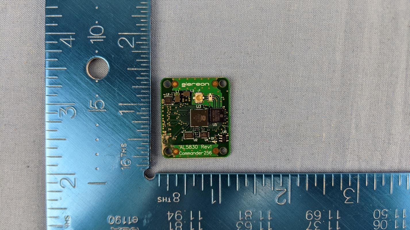
U9YAL5830
Apr 19, 2021UWB Parallel Interface Module (SBU & SAB)
Equipment Class
UWB - Ultra Wideband Transmitter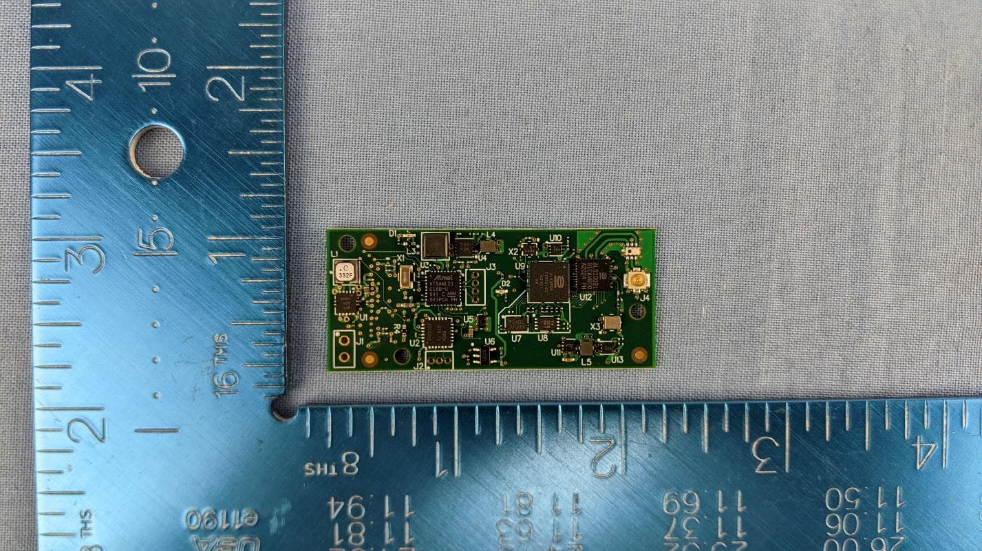
U9YAL5835
Apr 19, 2021UWB Serial Interface Module (SBU & SAB)
Equipment Class
UWB - Ultra Wideband Transmitter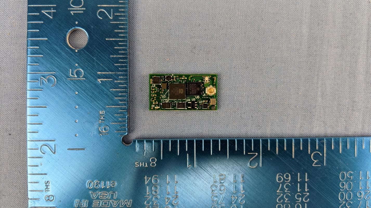
U9YAL5808
Apr 13, 2021UWB Octal SPI Module (SBU & SAB)
Equipment Class
UWB - Ultra Wideband Transmitter
U9YAL5833
Apr 13, 2021UWB Parallel Interface Module (SBU & SAB)
Equipment Class
UWB - Ultra Wideband Transmitter
U9YHS6618A
Aug 26, 2012Wireless USB Dongle
Equipment Class
UWB - Ultra Wideband Transmitter