U9YAL5730Wireless HDMI PC Extender
Alereon, Inc
Click to zoom
Application Details
- Equipment Class
- UWB - Ultra Wideband Transmitter
- Date of Grant
- Mar 03, 2010
- Application Purpose
- Original Equipment
- Date of Application
- Jan 28, 2010
- Equipment Note
- Wireless HDMI PC Extender
- Frequency Range
- 3168.00000000 - 4752.00000000
- Company
- Alereon, Inc
- Country
- United States
Documents & Files
Document Text
Text extracted from the exhibit documents filed with the FCC. Open a document above to read the original.
Attestation Statements
1/6/2010 3:29:22 PM Alereon AL51000 Characteristic p.1/2 Alereon AL51000 antenna used in AL5730 HDMI PC Extender The AL51000 antenna is a directional type antenna designed specifically for use in the AL5730 Worldwide Wireless HDMI PC Extender. The topology of this antenna is a broadband dipole radiator with a reflector and director element. The objective of this topology is to produce an antenna having a broadly directional characteristic. The following data plots describe the gain and radiation pattern of this antenna. 1. Gain vs. Frequency AL51000 BG#1 Frequency (MHz) Peak Gain (dBi) V Beamwidth (°) H Beamwidth (°) H directivity (dB) 3432 4.25 70 143 9.43 3960 4.02 76 181 12.79 4488 1.57 78 201 12.32 Peak Gain 0 2 4 6 8 10 12 14 30 00 31 00 3 2 0 0 33 00 34 00 35 00 36 00 3 7 0 0 38 00 39 00 40 00 41 00 4 2 0 0 43 00 44 00 4 5 0 0 46 00 47 00 48 00 49 00 5 0 0 0 Frequency (MHz) Peak Gain / Directivity (dB) 0 50 100 150 200 250 Beamwidth (Degrees) Peak Gain-HPeak Gain-VV-Plane directivity H-Plane directivity-3dB BW-V-3dB BW-H 1/6/2010 3:29:22 PM Alereon AL51000 Characteristic p.2/2 2. Radiation Pattern BG1 Radiation Pattern Horizontal Beamw idth -15 -10 -5 0 5 343239604488
Cover Letter(s)
[7600 N. Capital of Texas Hwy] [Building C] [Suite 200] [Austin, TX 78731] ph [512-345-4200] fx [512-345-4201] January 6, 2010 Chief, Authorizations Branch Federal Communications Commission 7435 Oakland Mills Road Columbia, MD 21046 To Whom It May Concern: Please be advised that Alereon, Inc. authorizes Professional Testing, Inc (PTI) to act on our behalf, until otherwise notified, for applications submitted to the Federal Communications Commission (FCC) regarding Ultra-Wideband (UWB) products. We certify that we are not subject to denial of federal benefits, that includes FCC benefits, pursuant to Section 5301 of the Anti-Drug Abuse ACT of 1988, U.S.C. 862. Further, no party, as defined in 47 CFR 1.2002(b), to the application is subject to denial of federal benefits, that includes FCC benefits. David Dickson Senior Principal RF Engineer Alereon, Inc.
Cover Letter(s)
[7600 N. Capital of Texas Hwy] [Building C] [Suite 200] [Austin, TX 78731] ph [512-345-4200] fx [512-345-4201] January 6, 2010 Chief, Authorizations Branch Federal Communications Commission 7435 Oakland Mills Road Columbia, MD 21046 Re: Alereon Application for Certification of Single Modular Transmitter FCC ID: U9YAL5730 To Whom It May Concern: Please be advised that the following exhibits are to be held confidential on behalf of Alereon: Schematics Block Diagrams Bill of Materials Additionally, Alereon requests short-term confidentiality for the following exhibits. Internal and external photographs This application contains technical information that Alereon considers to be trade secrets and proprietary. If made public, the information might be used to the disadvantage of the applicant in the market place. David Dickson Senior Principal RF Engineer Alereon, Inc.
Cover Letter(s)
[7600 N. Capital of Texas Hwy] [Building C] [Suite 200] [Austin, TX 78731] ph [512-345-4200] fx [512-345-4201] p. 1/2 January 15, 2010 Chief, Authorizations Branch Federal Communications Commission 7435 Oakland Mills Road Columbia, MD 21046 Subject: Request for unlicensed Modular Transmitter Approval. Reference: FCC 07-56A1 47 CFR 15.212 To Whom It May Concern: Alereon, Inc. hereby requests FCC Equipment Authorization as a Single Modular Transmitter of the Alereon, Inc. Model AL5730 Worldwide Wireless HDMI PC Extender Module, FCC ID: U9YAL5730. Alereon, Inc. intends to manufacture this device and market it as a computer modular component. This letter addresses the information required by points one through eight of 47 CFR 15.212. 1. The modular transmitter must have its own RF shielding. All shielding necessary for normal operation is accomplished by the multi-layer construction of the printed wiring board which incorporates multiple grounded conductor layers shielding all critical radio- frequency circuits including the frequency-determining components. As this transmitter is designed to operate stand-alone in its own enclosure, connected to industry-standard interfaces, no additional shielding is incorporated to minimize coupling such as might occur if the module were incorporated within another unit. 2. The modular transmitter must have buffered modulation/data inputs. The Alereon AL5730 receives data via the industry-standard HDMI or VGA interfaces. The HDMI interface is implemented within the SII9034 integrated circuit as may be seen on sheets thirteen and fourteen of the schematic diagram included in the filing for FCC Equipment Authorization. The VGA interface is implemented within the DL125 integrated circuit as may be seen on sheets twelve and fifteen of the schematic diagram included in the filing for FCC Equipment Authorization. These digital interfaces limit the data rate and modulation. 3. The modular transmitter must have its own power supply regulation. The Alereon AL5730 receives power from an external +5.0 Volt power unit. The +5.0 Volt source is conditioned on the module to power a +3.3V domain and the +1.2V digital subsystem domain plus three additional power domains required by the module circuitry; +2.6V, +2.4V and +1.8V. The power regulation topology may be seen on sheet twenty of the schematic diagram included in the filing for FCC Equipment Authorization. 4. The modular transmitter antenna must comply with the antenna and transmission system requirements of sections 15.203, 15.204(b) and 15.204(c). The antenna of the Alereon AL5730 is a directional dipole type. The antenna is intended to be permanently [7600 N. Capital of Texas Hwy] [Building C] [Suite 200] [Austin, TX 78731] ph [512-345-4200] fx [512-345-4201] p. 2/2 mounted inside of the product housing and the connector is not accessible to the user. The U.FL connector complies with the requirement of FCC 15.203 for a unique coupling. 5. The modular transmitter must be tested in a stand-alone configuration. As described in section 1.3 of the test report included in the filing for FCC Equipment Authorization, the AL5730 UWB Module plus antenna was tested without a housing. For the tests reported the AL5730 was connected to the USB port of a standard P.C. using a USB interface board to furnish connection to the factory test port on the AL5730 PCBA. This arrangement of the unit, interface board and P.C., represents the factory test and calibration configuration, not accessible to the user but which provides the necessary control of the unit to execute the FCC required tests for compliance. The AL5730 is designed with an industry-standard HDMI connector as its electrical and mechanical interface to the host system and with the industry standard Mini-D video connector as its electrical and mechanical interface to an attached VGA display device and a standard stereo jack for speakers connection. 6. The modular transmitter must be equipped with either a permanently affixed label or must be capable of electronically displaying its FCC identification number. The Alereon AL5730 is intended to be placed within an enclosure unique to the brand I.D. under which it is marketed. The prescribed label with the FCC Identifier will be applied to the outside of the housing. Additionally, the module will have a label affixed to the PCBA which includes the FCC identifier. An example of the label which will be used is included in the filing for FCC Equipment Authorization. 7. The modular transmitter must comply with any specific rule or operating requirements applicable to the transmitter. Part 15.519 of the FCC rules and Regulations requires that a UWB transmitter shall transmit only when it is sending information to an associated receiver. That rules part also requires that the UWB intentional radiator shall cease transmission within 10 seconds unless it receives an acknowledgement from the associated receiver that its transmission is being received. An acknowledgment of reception must continue to be received by the UWB intentional radiator at least every 10 seconds or the UWB device must cease transmitting. This requirement is met by design and is implemented by the firmware encoded into the device. 8. The modular transmitter must comply with any applicable RF exposure requirements in its final configuration. There are no RF exposure requirements for UWB devices operating under subpart F of the FCC Rules and Regulations. David M. Dickson Sr. Principal RF Engineer Alereon, Inc.
External Photos
External Photos
ID Label/Location Info
Alereon AL5730 Worldwide Wireless HDMI PC Extender Module FCC ID: U9YAL5730 MAC ID: XXXXXXXXX XXXXX
ID Label/Location Info
Location of identification label on Alereon AL5730. The identification label of the AL5730 will be placed on the PCBA as shown in the following photograph. For clarity; an enlarged view of the label. AL5730 identification label.
Internal Photos
Internal Photos
Operational Description
1/18/2010 1:47:55 PM Alereon RET Operating Instructions AL5730 p.1/19 Instructions for Operation of Alereon R adio Evaluation Tool (RET) Software I. Introduction The Alereon UWB radio transmitter normally operates by intermittent transmissions. Data transfers between host and device radios is bursty by nature and this results in intermittent transmissions. The FCC requires that UWB transmitters be tested in continuous transmit mode so that instruments may determine the true transmitted PSD. To achieve this testing requirement it is necessary to use the Alereon development software, the RET tool. These instructions provide information about how to use the RET tool to control the transmitter operation. II. Specific instructions for the Alereon AL5730 Worldwide Wireless HDMI PC Extender transmitter test (step-by-step). The Alereon RET software controls the Alereon UWB chipset via a USB interface. The Alereon AL5730 Worldwide Wireless HDMI PC Extender does not implement a USB interface. For testing purposes it is necessary to use a USB to UART interface board that is connected to the UART factory test port of the AL5730. The connection between the AL5730 test specimen and the USB – UART interface is shown in the following picture: USB- UART Interface DUT, AL5730 1/18/2010 1:47:55 PM Alereon RET Operating Instructions AL5730 p.2/19 Connection of UART interface cable from USB-UART interface board to AL5730. The factory test UART port connector is non-polarized, please observe the mark on the connector and orient the connector as in the picture. The test PC has been configured with the RET software and the AL5730 test specimens drivers have been installed to this computer. Please refer to Appendix B of this document for information regarding the configuration of the test PC. 1. Start the PC and wait until windows finishes loading. 2. Apply power to the AL5730 by inserting the connector of the power supply into J3. J7 Pin 1 1/18/2010 1:47:55 PM Alereon RET Operating Instructions AL5730 p.3/19 3. Press and hold the button on the USB-UART interface board while inserting the USB connector of the cable to the USB-UART interface board into the upper USB socket at the Right-hand side near to the rear of the PC. 4. Release the button on the USB-UART interface board. Proper installation will be indicated by the flashing Green light of the specimen. Note: The Alereon drivers are pointed to the USB socket into which the specimen was originally installed. If it is desired or necessary to make the compliance test with the specimen in another USB socket the PC will request to install drivers pointed to that USB socket. Please refer to Appendix A of this document for information on the drivers installation process. 3. Click on the CustomerRET icon on the PC desktop to start the RET software tool. 1/18/2010 1:47:55 PM Alereon RET Operating Instructions AL5730 p.4/19 The RET opening screen will appear after the RET software loads. 4. Select Device-MCU as the Platform type and then click CONTINUE. 1/18/2010 1:47:55 PM Alereon RET Operating Instructions AL5730 p.5/19 When the RET program has successfully connected to the specimen and taken control of it the following Device Config. screen will appear. 5. Click on the Load PHY Script button to configure the specimen for operation. The indicator within the button will turn Green indicating a successful operation. These steps conclude configuring the specimen for RET control. 6. Click on the Transmit Tests tab at the top of the Device Config. Screen. This will open the transmitter control screen. From this screen transmitter operating parameters may be selected as required for testing. The following are possible to control: 5 6 1/18/2010 1:47:55 PM Alereon RET Operating Instructions AL5730 p.6/19 Band Group; click on the desired band group: 1, 3 or 6 the active band group is indicated with a check mark and after selection is completed the button will indicate the selection. Note: Being a universal test tool for all products, the factory test allows access to all band groups. The product configuration of the AL5730 will restrict operation to BG#1 only. This restriction is accomplished by the device configuration firmware loaded at factory test. 1/18/2010 1:47:55 PM Alereon RET Operating Instructions AL5730 p.7/19 Channel; click on the desired channel. Channel TFC1 is the 1-2-3 hop code sequence and is normally used for compliance testing. Note: Being a universal test tool for all products, the factory test allows access to all channeld. The product configuration of the AL5730 will restrict operation to TFC1, 2, 3 and 4 (the hopping codes) only. This restriction is accomplished by the device configuration firmware loaded at factory test. 1/18/2010 1:47:55 PM Alereon RET Operating Instructions AL5730 p.8/19 PHY Rate; click on the desired PHY Data Rate, 200 Mbps is QPSK modulated and is normally used for compliance testing as this is a more complex modulation than the lower rates and produces the longest data sequences for the test. The boxes below the PHY Rate button accept typed entries, the entries that are present at starting are the normal default values which should be used for the compliance test. 1/18/2010 1:47:55 PM Alereon RET Operating Instructions AL5730 p.9/19 To the right of the second box (Number of Packets) is a Green button, click on this button to change it to Continuous Transmit. 1/18/2010 1:47:55 PM Alereon RET Operating Instructions AL5730 p.10/19 MAC TPC; to the right of the MAC TPC box, click on the Auto TPC button. This will change the control to Manual TPC. 1/18/2010 1:47:55 PM Alereon RET Operating Instructions AL5730 p.11/19 DAC TPC; select -14dB. RFIC TPC; select -4dB. 1/18/2010 1:47:55 PM Alereon RET Operating Instructions AL5730 p.12/19 After all of the desired parameters have been chosen, click on the Blue Start Test button, the transmitter will be active under the chosen parameters and will operate continuously until the Red Stop Test but…
Text truncated - open the document above for the full version.
Operational Description
Rev. 1.0 – Dec 2009Confidential Release Under Alereon NDA USERS GUIDE OVERVIEW This document is a users guide to explain how to establish a wireless connection using an Alereon HWA and an AL5730 Harbour board. 1.0INSTALLATION There are two software packages necessary to use the AL5730 Harbour board with the AL5604 Host Wire Adapter (HWA). •The Wireless USB Manager - This software package includes the drivers for the HWA. •The DispalyLink Driver Package - This software package contains the drivers necessary to enable the video output of the Harbour board. 1.1Installing the Wireless USB Manager Alereon provides MSI based installers. Each installer is designated by the platform it supports in the filename. For example, •Setup_wusb_X86_XXXX.msi - indicates that this MSI is for 32 bit systems •Setup_wusb_X64_XXXX.mdi - indicates that this MSI is for 64 bit systems You can launch the installation process by double clicking the MSI package. Please follow the following steps in order to install Alereon's Wireless USB Manager. Note:Wireless USB Manager has a dependency on Microsoft .NET 2.0. you will have to install this software manually before going through the setup or connect the PC to the internet and the setup will automatically download this dependency from the internet. Microsoft .NET is included in Windows Vista and newer operating systems. Step 1: Complete the installation of the Wireless USB manager by running the included Wireless USB installer. If you need more detailed instructions for this please see the included Wireless USB Manager User’s Guide. Step 2: Insert the HWA in to an open USB port on the PC and allow the drivers to load. AL5730 Harbour Users Guide NoWires Users GuideConfidential 2Rev. 1.0 1.2Installing the DisplayLink Driver Package Alereon provides an installer package for the DisplayLink device on the Harbour board. Installation of this driver package is necessary to enable the video output of the Harbour board. The DisplayLink installer files are named in this manner: •Displaylink-5.X.XXXXX.exe - The X’s indicate the driver package version. You can launch the installation process by double clicking the exe file. Please follow the following steps in order to install Alereon's Wireless USB Manager. Note:In some cases, separate driver packages will be included for the various supported operating systems. Step 3: Run the DisplayLink installer. Step 4: Reboot the PC. If you choose not to reboot, the Harbour video output may not work correctly until a reboot is completed. 2.0ESTABLISHING A WIRELESS CONNECTION Step 5: Open the Wireless USB manager and select the "Connection Rules" tab. Step 6: Click the On/Off button under "Wireless Associations". The button should turn green. If this button is disabled, please ensure that the HWA drivers are properly loaded. Please see the Wireless USB Manager User’s Guide. Step 7: Connect the power cable to the AL5730 Harbour board. You must do this within 3 minutes after enabling wireless associations in the Wireless USB Manager. Step 8: After a few seconds, the Wireless USB Manager should report that a device wants to wirelessly associate. When this happens enter the PIN "Alereon!". The A is capitalized and there is an exclamation mark at the end. The quotes are not part of the PIN. Step 9: The PIN association should succeed and the in a few seconds the device should connect and enumerate. If the PIN association was successful but the device fails to connect, power cycle the device and it should connected within a few seconds. If for any reason this process fails to prompt you for a PIN please remove the HWA and remove power from the Harbour board, then repeat steps 5 to 8. Step 10: Your Harbour adapter should now have a wireless connection to the host PC. Connect a monitor or TV using a VGA or HDMI cable and enjoy. 3.0USAGE NOTES AND RECOMMENDATIONS •Optimal Resolution for Video performance - The DisplayLink drivers perform more advanced video compression when TV specific resolutions are used. When typical PC resolutions are used, the video performance may be degraded in some cases. The recomm- mended output resolutions for the Harbour board are 640X480, 720x480, 800x600 and 1280x720. Choosing other resolutions could degrade video performance. •Changing the Resolution (Windows XP and Vista) - You can change the resolution of the Harbour attached display using the DisplayLink Manger which can be found in the Windows system tray. The icon has a blue monitor with a wire attached. An example is provided to the right of this paragraph. •Changing from Mirror to Extended Mode (Windows XP and Vista) - You can change the mode of the Harbour attached display using the DisplayLink Manger which can be found in the Windows system tray. In Mirror mode, the image and resolution of the main display is also used on the second display. In extended mode, the resolution output of the Harbour can be changed independently of the main PC display. •Windows 7 - The Mode and resolution of the Harbour attached display must be changed through the display resolution settings included in Windows 7. To access this functionality right click on the desktop and select "display resolution". •Playing Full Screen Video in Windows XP - The DisplayLink drivers have a limitation when playing full screen Flash video. Typical examples of Flash video are YouTube and Hulu. The workaround for this is to disable hardware acceleration in the flash video. On most PC’s this changed is retained by the flash player, so these steps should need to be performed only once. Here are the steps to perform this workaround: •1. Right click on the flash video, select Settings •2. Go to the Display card •3. Uncheck "Enable hardware acceleration" • ConfidentialNoWires Users Guide Rev. 1.03 4.0THROUGHPUT TESTING An application for video throughput testing is included on the CD. This application is called AL_Flood. AL_Flood is a graphical wrapper for the DisplayLink Nivoutil throughput test applicat…
Text truncated - open the document above for the full version.
Test Report
Project 10451-10 Alereon, Inc. AL5730 Prepared for: Alereon, Inc. 7600 N. Capital of Texas Hwy. Building C Suite 200 Austin, Texas 78731 By Professional Testing (EMI), Inc. 1601 N. A.W. Grimes Blvd., Suite B Round Rock, Texas 78665 January 14, 2009 CERTIFICATION Wireless Test Report Alereon, Inc. AL5730 10451-10 Page 2 of 36 Table of Contents Title Page ........................................................................................................................................1 Table of Contents ...........................................................................................................................2 Certificate of Compliance...............................................................................................................3 1.0 Introduction........................................................................................................................4 1.1 Scope................................................................................................................................4 1.2 EUT Description ..............................................................................................................4 1.3 EUT Operation.................................................................................................................4 1.4 Test Site ...........................................................................................................................4 1.5 Applicable Documents.....................................................................................................5 2.0 Power Line Conducted Emissions ....................................................................................6 2.1 Test Procedure .................................................................................................................6 2.2 Test Criteria .....................................................................................................................6 3.0 Average Output Power ......................................................................................................6 3.1 Test Procedure .................................................................................................................6 3.2 Test Criteria .....................................................................................................................7 4.0 UWB Bandwidth ................................................................................................................7 4.1 Test Procedure .................................................................................................................7 4.2 Test Criteria .....................................................................................................................7 5.0 Spurious Radiated Emissions............................................................................................7 5.1 Test Procedure .................................................................................................................7 5.2 Test Criteria .....................................................................................................................8 6.0 Radiated Emissions in GPS Bands ...................................................................................8 6.1 Test Procedure .................................................................................................................8 6.2 Test Criteria .....................................................................................................................9 7.0 Peak Emissions FM within 50 MHz Bandwidth .............................................................9 7.1 Test Procedure .................................................................................................................9 7.2 Test Criteria .....................................................................................................................9 8.0 Antenna Requirements ......................................................................................................9 8.1 Evaluation Procedure .....................................................................................................10 8.2 Evaluation Criteria .........................................................................................................10 9.0 Modifications ....................................................................................................................10 10.0 Test Equipment ................................................................................................................10 Appendix A Test Setup Diagrams........................................................................................12 Appendix B Test Results.......................................................................................................15 End of Report .............................................................................................................................36 THIS REPORT SHALL NOT BE REPRODUCED EXCEPT IN FULL, WITHOUT THE WRITTEN APPROVAL OF PROFESSIONAL TESTING (EMI), INC. 10451-10 Page 3 of 36 Applicant: Alereon, Inc.. Applicant’s Address: 7600 N. Capital of Texas Hwy. Bldg. C, Suite 200 Austin, TX 78731 FCC ID: U9YAL5730 Project Number: 10451-10 Test Dates: December 15 - 17, 2009 The Alereon, Inc. AL5730 was tested to and found to be in compliance with FCC 47 CFR Part 15 Subpart F. The highest emissions generated by the above equipment are listed below: Parameter Frequency (MHz) Level Limit Margin (dB) Mains Conducted .169 33.3 55.4 -22.1 Radiated Spurious 144.84 27.4 dBμV/m 30 dBμV/m -2.6 Output Power 3432 -41.97 dBm .00006 mw -41.3 dBm -0.67 UWB Bandwidth 10 dB Low (3432 MHz) Mid (3960 MHz) High (4488 MHz) 505.6 MHz 519.9 MHz 502 MHz I, Jason Anderson, for Professional Testing (EMI), Inc., being familiar with the FCC rules and test procedures have reviewed the test setup, measured data and this report. I believe them to be true and accu…
Text truncated - open the document above for the full version.
Test Setup Photos
Test Setup Photos Conducted Emissions Radiated Emissions Spurious / Harmonics
Contact Information
Applicant
Parmveer Singh(Director of Systems Applications)
Technical Contact
Professional Testing EMI Inc.Layne Lueckemeyer
[email protected]512-244-3371
1601 North A.W. Grimes · Round Rock, Texas · United States
Test Firm
Professional Testing (EMI), Inc.Robert McCollough
Technical Specifications
| # | Rule Parts | Frequency Range | Power Output |
|---|---|---|---|
| 1 | 15F | 3.17 GHz - 4.75 GHz | - |
Other Applications from Alereon, Inc
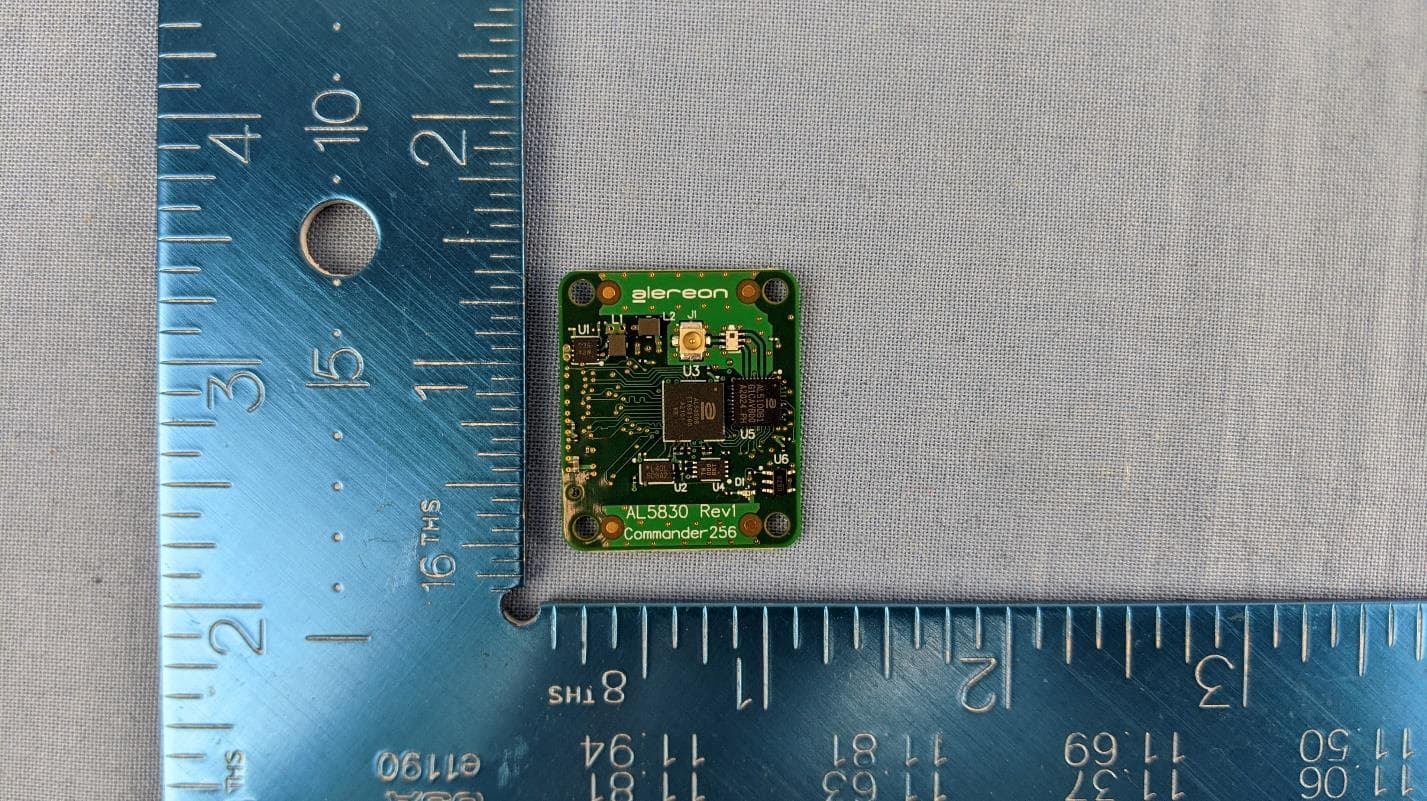
U9YAL5830
Apr 19, 2021UWB Parallel Interface Module (SBU & SAB)
Equipment Class
UWB - Ultra Wideband Transmitter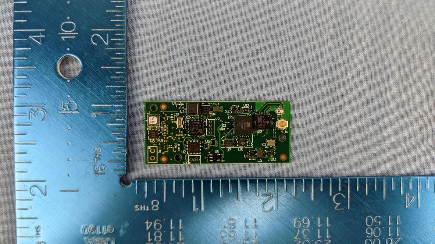
U9YAL5835
Apr 19, 2021UWB Serial Interface Module (SBU & SAB)
Equipment Class
UWB - Ultra Wideband Transmitter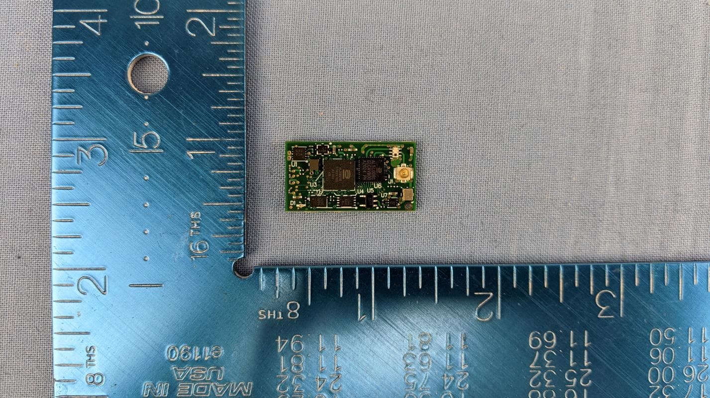
U9YAL5808
Apr 13, 2021UWB Octal SPI Module (SBU & SAB)
Equipment Class
UWB - Ultra Wideband Transmitter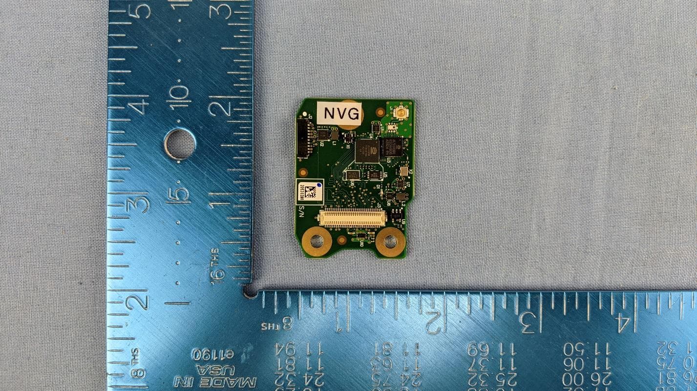
U9YAL5833
Apr 13, 2021UWB Parallel Interface Module (SBU & SAB)
Equipment Class
UWB - Ultra Wideband Transmitter
U9YHS6618A
Aug 26, 2012Wireless USB Dongle
Equipment Class
UWB - Ultra Wideband Transmitter