U9YAL6621Worldwide Wireless USB Side Device Radio Card
Alereon, Inc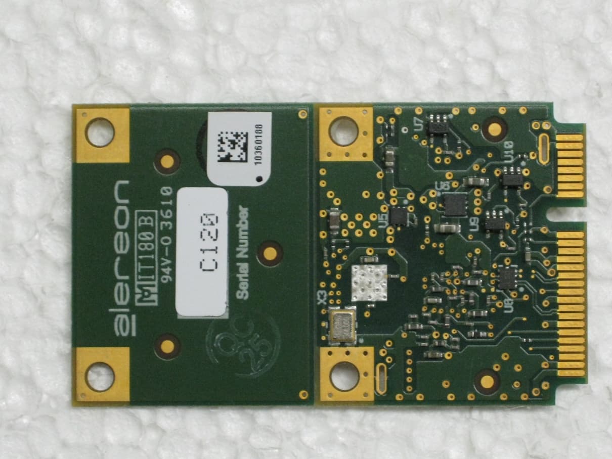
Click to zoom
Application Details
- Equipment Class
- UWB - Ultra Wideband Transmitter
- Date of Grant
- Feb 14, 2011
- Application Purpose
- Original Equipment
- Date of Application
- Jan 03, 2011
- Equipment Note
- Worldwide Wireless USB Side Device Radio Card
- Frequency Range
- 7392.00000000 - 8976.00000000
- Company
- Alereon, Inc
- Country
- United States
Documents & Files
Document Text
Text extracted from the exhibit documents filed with the FCC. Open a document above to read the original.
Users Manual
UG-AL5721_1.0 P.1/7 AL6621 Worldwide Wireless USB Device Radio Card User Guide INTRODUCTION The AL6621 PCB Radio module is a complete compact device radio reference design that enables quick design of UWB enabled products. The AL6621 combines the Alereon AL5100/AL6301 chipset along with on board power supplies, an antenna output and a USB 2.0 system interface. 1.0 REFERENCE DESIGN FEATURES • Optimized Performance with AL5100 (3.1GHz to 8.976GHz) WiMedia BG#1, 3, 6 • Complete Baseband Processor (BBP) and Media Access Controller (MAC) • High Precision Data Path and Data Converters allowing reliable link at extended ranges • Fully Integrated MAC Protocol Engine Supports All Industry Standards WiMedia protocols - Certified Wireless USB - WiMedia Link Layer Protocol - Bluetooth 3.0 (supported by future SW releases) • Industry Standard Interfaces - USB 2.0 – Data - USB 2.0 – WiMedia Cable Association • Operates from a single (+3.3 V, regulated) supply • Small Form Factor (Minicard form factor) • 3 GPIO lines for LED Indicators or additional system control signals 2.0 Usage and Documentation The AL6621 is a complete, self-contained UWB radio module requiring only +3.3V regulated power from the host system and providing USB 2.0 interfaces to the host system for data and the WiMedia association function. The AL6621 is intended to provide a simple path for a wired USB product design to migrate to a UWB enabled wireless USB product design. The AL6621 is a wireless USB certified platform and has received FCC approval as a Modular UWB transmitter under subpart F of the FCC rules with the FCC ID: U9YAL6621. The product implementation can apply these approvals to the product which incorporates the AL6621. This document provides an outline of the purpose and functionality provided by the AL6621, complete information for the product system designer is contained in the Alereon Reference Design Kit (RDK) package consisting of: Schematic diagram, BOM, and PCB fabrication information including a full Gerber data set. UG-AL5721_1.0 P.2/7 3.0 User I/O Interface AL6621 Connector Function Pin # Pin # Function NC 1 2 3.3V NC 3 4 GND NC 5 6 NC NC 7 8 NC GND 9 10 NC NC 11 12 NC NC 13 14 NC GND 15 16 USB VBUS Host_ Select# 17 18 GND NC 19 20 W_Disable# GND 21 22 Association_CLR# NC 23 24 NC NC 25 26 GND GND 27 28 Assoc. D+ GND 29 30 Assoc. D- NC 31 32 Assoc. VBUS NC 33 34 GND GND 35 36 USB D- C2D 37 38 USB D+ RST#/C2CLK 39 40 GND AL_GPIO_2 41 42 Dock_LED AL_GPIO_4 43 44 Security_LED# AL_GPIO_5 45 46 Data_LED# AL_GPIO_7 47 48 NC Host_Connect_LED 49 50 GND NC 51 52 3.3V Figure 1, Connector Pins Configuration UG-AL5721_1.0 P.3/7 AL6621 Pin Function Description Pin # Pin Name I/O Description 1 NC No Connection 2 3.3V +3.3V Regulated power from host system 3 NC No Connection 4 GND Ground connection 5 NC No Connection 6 NC No Connection 7 NC No Connection 8 NC No Connection 9 GND Ground connection 10 NC No Connection 11 NC No Connection 12 NC No Connection 13 NC No Connection 14 NC No Connection 15 GND Ground connection 16 USB VBUS I +5V USB Vbus Signal from host system 17 Host_Select# I (1) Low = True 3.3V CMOS signal, allows host system to provide control of selection among multiple hosts associated to UWB radio. (2) Test function, holding Host_Select# asserted at +3.3V power application to the AL5721 and then switching it un-asserted places the aL5721 into Administrative Mode for control by Alereon manufacturing test utility software 18 GND Ground connection 19 NC No Connection 20 W_Disable# I Low = True 3.3V CMOS signal, assertion of W_Disable# completely disables the radio system. 21 GND Ground connection 22 Association_CLR# I Low = True 3.3V CMOS signal, assertion of Association_CLR clears all stored host associations 23 NC No Connection 24 NC No Connection 25 NC No Connection 26 GND Ground connection 27 GND Ground connection 28 Assoc. D+ I/O USB D+ of Association signal 29 GND Ground connection 30 Assoc. D- I/O USB D- of Association signal 31 NC No Connection 32 Assoc. VBUS I +3.3V USB Vbus Signal from association connector 33 NC No Connection 34 GND Ground connection 35 GND Ground connection UG-AL5721_1.0 P.4/7 36 USB D- I/O USB D- data signal from host system 37 C2D I/O Test signal for 8051CF326 USB controller 38 USB D+ I/O USB D+ data signal from host system 39 RST#/C2CLK I/O Test signal for 8051CF326 USB controller 40 GND Ground connection 41 AL_GPIO_2 I/O MAC GPIO signal, functionality may be determined by customer definition 42 Dock_LED O LED drive pin, functionality per table 2 43 AL_GPIO_4 I/O MAC GPIO signal, functionality may be determined by customer definition 44 Security_LED# O LED drive pin, functionality per table 2 45 AL_GPIO_5 I/O MAC GPIO signal, functionality may be determined by customer definition 46 Data_LED# O LED drive pin, functionality per table 2 47 AL_GPIO_7 I/O MAC GPIO signal, functionality may be determined by customer definition 48 NC No Connection 49 Host_Connect_LED O LED drive pin, functionality per table 2 50 GND Ground connection 51 NC No Connection 52 3.3V +3.3V Regulated power from host system Table 1. Pin Descriptions 4.0 DESIGN CONSIDERATIONS 4.1 Power One +3.3 V power supply at max data rate average current of 500 mA with peak at 750 mA. Connector pins #2 and 52 (+3.3V) are connected in common, both should connect to the host system power rail. Connector pins #4, 9, 15, 18, 21, 26, 27, 29, 34, 35, 40, and 50 are connected in common, all should connect to the host system ground. 4.2 LED Indicator Functions Name Functional Description Dock LED Steady flashing when dock power is applied and radio is beaconing but not connected to a host. LED is solid when a wireless connection is made to a Host PC. Security LED Normally off, Flashes during cable association process, Goes solid when a successful cable association is made. During wireless operation, this LED is off when there is not wireless connection to a host, when successful Secure wireless connection is made to a pre-associ…
Text truncated - open the document above for the full version.
Cover Letter(s)
[7600 N. Capital of Texas Hwy] [Building C] [Suite 200] [Austin, TX 78731] ph [512-345-4200] fx [512-345-4201] January 5, 2011 Chief, Authorizations Branch Federal Communications Commission 7435 Oakland Mills Road Columbia, MD 21046 To Whom It May Concern: Please be advised that Alereon, Inc. authorizes Professional Testing, Inc of Round Rock Texas to act on our behalf, until otherwise notified, for applications submitted to the Federal Communications Commission (FCC) regarding Ultra-Wideband (UWB) products. We certify that we are not subject to denial of federal benefits, that includes FCC benefits, pursuant to Section 5301 of the Anti-Drug Abuse ACT of 1988, U.S.C. 862. Further, no party, as defined in 47 CFR 1.2002(b), to the application is subject to denial of federal benefits, that includes FCC benefits. David Dickson Senior Principal RF Engineer Alereon, Inc.
Cover Letter(s)
[7600 N. Capital of Texas Hwy] [Building C] [Suite 200] [Austin, TX 78731] ph [512-345-4200] fx [512-345-4201] January 5, 2011 Chief, Authorizations Branch Federal Communications Commission 7435 Oakland Mills Road Columbia, MD 21046 Subject: Alereon request for confidentiality. FCC ID: U9YAL6621 To Whom It May Concern: Short-term confidentiality Pursuant to DA 04-1705 of the Commission’s pubic notice, in order to comply with the marketing regulations in 47CFR §2.803 and the importation rules in 47 CFR §2.1204, while ensuring that business sensitive information remains confidential until the actual marketing of newly authorized devices. We are requesting the commission to grant short-term confidentiality request on the following attachments until September 11, 2010. 1. Internal Photographs 2. External Photographs Permanent confidentiality Pursuant to Sections 0.457 and 0.459 of the Commission’s Rules, the Applicant Hereby requests confidential treatment of information accompanying this Application As outlined below: 1. Block Diagram 2. Schematics 3. Bill of Materials The above materials contain trade secrets and proprietary information not customarily released to the public. The public disclosure of these materials may be harmful to the applicant and provide unjustified benefits to its competitors. The applicant understands that pursuant to Section 0.457 of the Rules, disclosure of this application and all accompanying documentation will not be made before the date of the Grant for this application. Should you require any further information, please contact the undersigned. Thank you for your consideration in this matter. David Dickson Senior Principal RF Engineer Alereon, Inc. Applicant : Alereon, Inc Address : 7600-C Suite 200 Capitol of Texas Highway Austin Texas USA 78731 E-mail : [email protected] 512 418 2137
Cover Letter(s)
[7600 N. Capital of Texas Hwy] [Building C] [Suite 200] [Austin, TX 78731] ph [512-345-4200] fx [512-345-4201] p. 1/2 January 5, 2011 Chief, Authorizations Branch Federal Communications Commission 7435 Oakland Mills Road Columbia, MD 21046 Subject: Request for unlicensed Modular Transmitter Approval. Reference: FCC 07-56A1 47 CFR 15.212 To Whom It May Concern: Alereon, Inc. hereby requests FCC Equipment Authorization as a Singular Modular Transmitter of the Alereon, Inc. Model AL6621 UWB Module, FCC ID: U9YAL6621. Alereon, Inc. intends to manufacture this device and market it as a computer modular component. This letter addresses the information required by points one through eight of 47 CFR 15.212. 1. The modular transmitter must have its own RF shielding. Shielding necessary for normal operation is accomplished by a metal shield enclosure which attaches to the printed wiring board and encloses the RF circuitry, including the frequency-determining element. 2. The modular transmitter must have buffered modulation/data inputs. The Alereon AL6621 receives data via the industry-standard USB 2.0 interface. This digital interface limits the data rate and modulation. 3. The modular transmitter must have its own power supply regulation. The Alereon AL6621 receives power from the host system. The +3.3 Volt source from the host system is filtered on the module to power a +3.3V domain and regulated on the module to produce the main +1.2V digital subsystem domain. The +3.3V domain is also regulated on the module to produce two additional power domains required by the module circuitry; +2.4V and +1.2V. The power regulation topology may be seen on sheet seven of the schematic diagram included in the filing for FCC Equipment Authorization. 4. The modular transmitter antenna must comply with the antenna and transmission system requirements of sections 15.203, 15.204(b) and 15.204(c). The antenna of the Alereon AL6621 UWB Module is one of two types: an external monopole, part number AL50001, which attaches to the AL6621 by a 60mm coaxial cable with a type U.FL connector or an external dipole, part number ADM6P700047, which attaches to the AL5712 by a 60mm coaxial cable with a type U.FL connector. These two antennas have the same and coverage pattern and are electrically equivalent differing only in their mechanical attachment to the product. The antenna is intended to be permanently [7600 N. Capital of Texas Hwy] [Building C] [Suite 200] [Austin, TX 78731] ph [512-345-4200] fx [512-345-4201] p. 2/2 attached to the product housing and the connector is not accessible to the user. The U.FL connector complies with the requirement of FCC 15.203 for a unique coupling. 5. The modular transmitter must be tested in a stand-alone configuration. As described in section 2.6.3 of the test report included in the filing for FCC Equipment Authorization, the AL6621 UWB Module plus antennas was tested without a housing. For the tests reported the module was attached to an Alereon designed test environment which provided power and a USB interface to the controlling computer. 6. The modular transmitter must be equipped with either a permanently affixed label or must be capable of electronically displaying its FCC identification number. The Alereon AL6621 is intended to be placed within the host system enclosure unique to the brand I.D. of the host system. The prescribed label with the FCC Identifier will be applied to the outside of the host system housing. Additionally, the module will have a label affixed which includes the FCC identifier. An example of the label which will be used is included in the filing for FCC Equipment Authorization. 7. The modular transmitter must comply with any specific rule or operating requirements applicable to the transmitter. Part 15.519 of the FCC rules and Regulations requires that a UWB transmitter shall transmit only when it is sending information to an associated receiver. That rules part also requires that the UWB intentional radiator shall cease transmission within 10 seconds unless it receives an acknowledgement from the associated receiver that its transmission is being received. An acknowledgment of reception must continue to be received by the UWB intentional radiator at least every 10 seconds or the UWB device must cease transmitting. This requirement is met by design and is implemented by the firmware encoded into the device. 8. The modular transmitter must comply with any applicable RF exposure requirements in its final configuration. There are no RF exposure requirements for UWB devices operating under subpart F of the FCC Rules and Regulations. David M. Dickson Sr. Principal RF Engineer Alereon, Inc.
External Photos
AL6621 External Photos
ID Label/Location Info
Alereon AL6621 Wireless UWB Module FCC ID: U9YAL6621 MAC ID: XXXXX XXXXXXXXX
ID Label/Location Info
Location of identification label on Alereon AL6621. The identification label of the AL6621 will be placed on the PCBA as shown in the following photograph. For clarity; an enlarged view of the label. AL6621 identification label.
Internal Photos
AL6621 Internal Photos
Operational Description
Alereon Confidential Page 1 1/5/2011 Theory of operation; Alereon AL6621 UWB Module. The Alereon AL6621 is a UWB radio device with a digital interface to the host computer. This device is intended to provide a short-range wireless connection for computers and peripheral devices. The AL6621 is powered from the host system to which it is attached. The digital interface between the host system and the AL6621 is the industry-standard USB 2.0 interface. The AL6621 operates in the frequency band defined in the FCC rules and Regulations for UWB devices. Specifically, it operates between the frequencies of 3.168 and 8.976 GHz per the industry-defined WiMedia 1.1 specification. The AL6621 is comprised of two integrated circuit devices and supporting circuitry for filtering and power conditioning. The AL6621 has a permanently attached antenna external to the housing. The schematic diagram shows a connector, Hirose type U.FL, in the RF path. This connector, is not accessible from outside of the unit housing. Following the antenna connector is a Diplexer type bandpass filter having two sections. The LB section has a passband from 3.1 GHz to 4.752 GHz, the HB section has a passband from 6.336GHz to 9.504GHz. This filter provides suppression of unwanted out of band transmitter emissions below 3.168 GHz and above 9,504 GHz as well as receiver interference rejection in the 2.4 GHz and 5.1 GHz bands. The AL5100 RF Transceiver generates the system reference frequency from a 44 MHz crystal resonator. The 44 MHz reference frequency is multiplied to 16.896 GHz internally in the AL5100 by a PLL multiplier. From this frequency the local oscillator frequencies for band frequencies for both transmit and receive modes are derived internally within the AL5100 by synthesis. The local oscillator frequencies are as listed as Fmid per the following table. In addition to the band frequencies, a 1056 MHz clock for ADCs and DACs within the AL5350 Baseband Processor/MAC is generated. The interface between the AL5100 RF Transceiver and the AL6301 Baseband Processor/MAC consists of the analog RX-I and –Q signals and the analog TX–I and –Q signals all of which are baseband, having 2 MHz to 264 MHz frequency band. The interface also includes a 1056 MHz clock signal and CMOS logic-level control signals which determine the band frequency and mode. The digital interface between the AL6301 Baseband Processor/MAC and the host system is selectable by a pin option on the module and in the AL6621 is permanently wired to be USB 2.0. Alereon Confidential Page 2 1/5/2011 The AL6621 circuit also incorporates a USB221 switch which serves to switch the USB interface between tow USB interfaces to the host system. One interface is the data path and the other is for link security at start-up. References. WiMedia Physical Layer Specification 1.1. WiMedai MAC-PHY Interface Specification 1.0. Universal Serial Buss Specification 2.0
Test Report
Project 11953-10 Alereon, Inc. AL6621 Worldwide Wireless USB Side Device Radio Card Prepared for: Alereon, Inc. 7600 N. Capital of Texas Hwy. Building C Suite 200 Austin, Texas 78731 By Professional Testing (EMI), Inc. 1601 N. A.W. Grimes Blvd., Suite B Round Rock, Texas 78665 November 29, 2010 CERTIFICATION Wireless Test Report Alereon, Inc. AL6621 11953-10 Page 2 of 56 Table of Contents Title Page ........................................................................................................................................1 Table of Contents ...........................................................................................................................2 1.0 Introduction .........................................................................................................................5 1.1 Scope ................................................................................................................................5 1.2 EUT Description ..............................................................................................................5 1.3 EUT Operation .................................................................................................................5 1.4 Test Site ...........................................................................................................................5 1.5 Applicable Documents .....................................................................................................6 2.0 Average Output Power .......................................................................................................7 2.1 Test Procedure .................................................................................................................7 2.2 Test Criteria .....................................................................................................................7 3.0 UWB Bandwidth .................................................................................................................7 3.1 Test Procedure .................................................................................................................7 3.2 Test Criteria .....................................................................................................................8 4.0 Spurious Radiated Emissions.............................................................................................8 4.1 Test Procedure .................................................................................................................8 4.2 Test Criteria .....................................................................................................................9 5.0 Radiated Emissions in GPS Bands ....................................................................................9 5.1 Test Procedure .................................................................................................................9 5.2 Test Criteria .....................................................................................................................9 6.0 Peak Emissions FM within 50 MHz Bandwidth ............................................................10 6.1 Test Procedure ...............................................................................................................10 6.2 Test Criteria ...................................................................................................................10 7.0 Antenna Requirements .....................................................................................................10 7.1 Evaluation Procedure .....................................................................................................10 7.2 Evaluation Criteria .........................................................................................................10 8.0 Modifications .....................................................................................................................11 9.0 Test Equipment .................................................................................................................11 Appendix A Test Setup Diagrams .....................................................................................13 Appendix B Test Results ...................................................................................................15 End of Report .............................................................................................................................56 THIS REPORT SHALL NOT BE REPRODUCED EXCEPT IN FULL, WITHOUT THE WRITTEN APPROVAL OF PROFESSIONAL TESTING (EMI), INC. 11953-10 Page 3 of 56 Applicant: Alereon, Inc.. Applicant’s Address: 7600 N. Capital of Texas Hwy. Bldg. C, Suite 200 Austin, TX 78731 FCC ID: U9YAL6621 Project Number: 11953-10 Test Dates: November 22 - 23, December 8, 2010 The Alereon, Inc. AL6621 was tested to and found to be in compliance with FCC 47 CFR Part 15 Subpart F. The highest emissions generated by the above equipment are listed below: Parameter Frequency (MHz) Level Limit Margin (dB) Radiated Spurious 457.32 31.2 dBμV/m 35.5 dBμV/m -4.3 Output Power 7656 -42.5 dBm .00006 mw -41.3 dBm -1.2 UWB Bandwidth 10 dB ADM6P Antenna Wimedia Band Group 1 Low (3432 MHz) Mid (3960 MHz) High (4488 MHz) 507.1 MHz 510.4 MHz 509.6 MHz UWB Bandwidth 10 dB ADM6P Antenna Wimedia Band Group 3 Low (6600 MHz) Mid (7128 MHz) High (7656 MHz) 513.0 MHz 512.2 MHz 510.5 MHz UWB Bandwidth 10 dB ADM6P Antenna Wimedia Band Group 6 Low (7656 MHz) Mid (8184 MHz) High (8712 MHz) 511.3 MHz 511.3 MHz 511.3 MHz 11953-10 Page 4 of 56 I, Jason Anderson, for Professional Testing (EMI), Inc., being familiar with the FCC rules and test procedures have reviewed the test setup, measured data and this report. I believe them to be true and accurate. Jason Anderson EMC Engineer This report has been reviewed and accepted by Alereon, Inc. The undersigned is responsible for ensuring that this device will continue to comply with …
Text truncated - open the document above for the full version.
Test Setup Photos
Test Setup Photos
Contact Information
Applicant
Parmveer Singh(Director of Systems Applications)
Technical Contact
Professional Testing (EMI), Inc.Layne Lueckemeyer
[email protected]512-244-3371
1601 North A.W. Grimes · Round Rock, Texas · United States
Test Firm
Professional TestingRobert McCollough Lenk
Technical Specifications
| # | Rule Parts | Frequency Range | Power Output |
|---|---|---|---|
| 3 | 15F | 7.39 GHz - 8.98 GHz | - |
Other Applications from Alereon, Inc
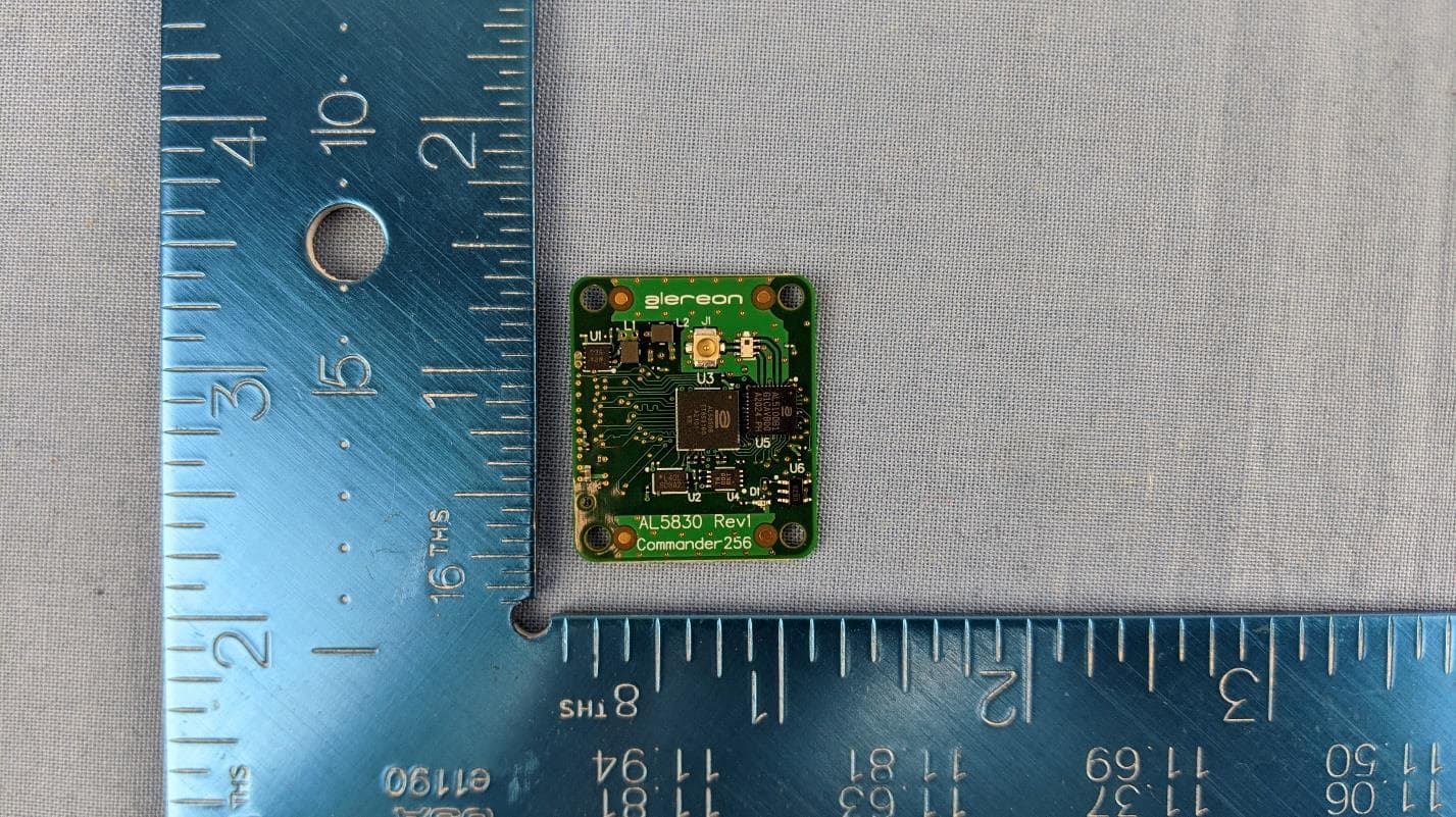
U9YAL5830
Apr 19, 2021UWB Parallel Interface Module (SBU & SAB)
Equipment Class
UWB - Ultra Wideband Transmitter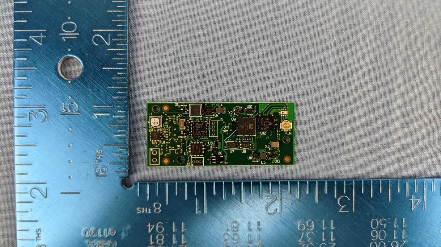
U9YAL5835
Apr 19, 2021UWB Serial Interface Module (SBU & SAB)
Equipment Class
UWB - Ultra Wideband Transmitter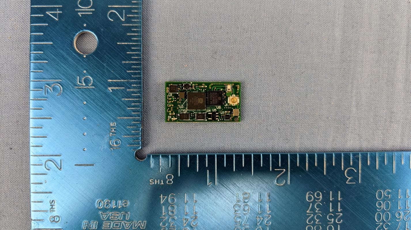
U9YAL5808
Apr 13, 2021UWB Octal SPI Module (SBU & SAB)
Equipment Class
UWB - Ultra Wideband Transmitter
U9YAL5833
Apr 13, 2021UWB Parallel Interface Module (SBU & SAB)
Equipment Class
UWB - Ultra Wideband Transmitter
U9YHS6618A
Aug 26, 2012Wireless USB Dongle
Equipment Class
UWB - Ultra Wideband Transmitter