UAG-RM1RM1
AwarePoint Corporation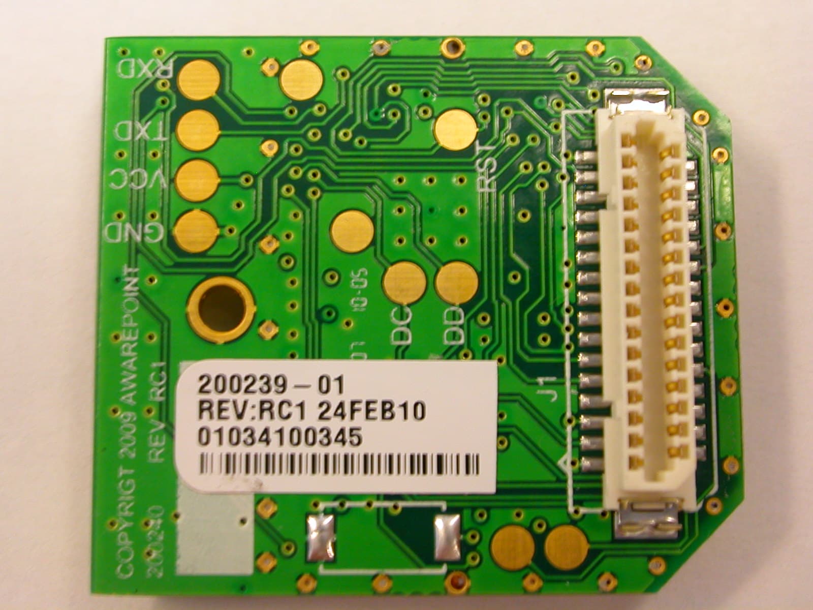
Click to zoom
Application Details
- Equipment Class
- DTS - Digital Transmission System
- Date of Grant
- May 18, 2010
- Application Purpose
- Original Equipment
- Date of Application
- May 18, 2010
- Equipment Note
- RM1
- Frequency Range
- 2405.00000000 - 2475.00000000
- Company
- AwarePoint Corporation
- Country
- United States
Documents & Files
Document Text
Text extracted from the exhibit documents filed with the FCC. Open a document above to read the original.
Users Manual
Awarepoint Installation Guide Version 2.3 Awarepoint Software Version 6.4 i Installation Guide v2.3 – 5/10 Confidential and Proprietary ©2010, Awarepoint Corporation Change History Version Date Description of Change 2.1 7/27/2009 Baseline release from previous versions. Changed paragraphs 7.1 and 7.2 to add S2U information. 2.2 3/31/2010 Updated to include the S2C/RM1 information and rewrite the regulatory info on sheet ii. Update appliance setup and make editorial comments throughout. 2.3 5/17/2010 Added Regulatory note OET Guide 65C. Updated with new Awarepoint Address ii Installation Guide v2.3 – 5/10 Confidential and Proprietary ©2010, Awarepoint Corporation Copyright Copyright 2010 Awarepoint Corporation, 600 W Broadway, Suite 250, San Diego, CA 92101 All rights reserved. This product or document is protected by copyright and distributed under licenses restricting its use, copying, distribution, and decompilation. No part of this product or document may be reproduced in any form by any means without prior written authorization of Awarepoint and its licensors, if any. Awarepoint, the Awarepoint logo, and Real-Tme Awareness Solution, are trademarks or registered trademarks of Awarepoint Corporation in the United States and in other countries. Microsoft is a registered trademark of Microsoft Corporation in the United States and/or other countries. ZigBee is a trademark for the ZigBee Alliance. iii Installation Guide v2.3 – 5/10 Confidential and Proprietary ©2010, Awarepoint Corporation Regulatory Compliance: The Awarepoint devices have received the following agency approvals: Bridge Model B1: FCC ID: UAG-00000000B100 (FCC Part 15.247) Bridge Model B2: FCC ID: UAG-B2 (FCC Part 15.247) IC ID: 7348A-B2 (IS RSS-210, Issue 7) FCC Part 15:2007, Class A (Radiated & Conducted) EN55022:2006, Class A (Radiated & Conducted) ICES-003:2004, Class A (Radiated & Conducted) Sensor Model S1: FCC ID: UAG-00000000R100 (FCC Part 15.247) UL 60950-1:2003 CSA C22.2 No. 60950-1:2003 Sensor Model S2: FCC ID: UAG-S2 (FCC Part 15.247) IC ID: 7348A-S2 (IS RSS-210, Issue 7) UL 60950-1:/R:2007-10 CSA C22.2 No. 60950-1:2003 Sensor Model S2U: FCC ID: UAG-S2 (FCC Part 15.247) IC ID: 7348A-S2 (IS RSS-210, Issue 7) IEC 60950-1:2005 Sensor Model S2C: FCC ID: UAG-RM1 (FCC Part 15.247) IC ID: 7348A-RM1 (IS RSS-210, Issue 7) IEC 60950-1:2005 Tag Model T1: FCC ID: UAG-00000000T100 (FCC Part 15.247) Tag Model T2: FCC ID: UAG-T2 (FCC Part 15.247) IC ID: 7348A-T2 (IS RSS-210, Issue 7) This device complies with Part 15 of the FCC Rules. Operation is subject to the following two conditions: (1) this Device may not cause harmful interference and (2) this Device must accept any interference received, including Interference that may cause undesired operation. CAUTION: Changes or modifications not expressly approved by the party responsible for compliance could void the user's authority to operate the equipment. CAUTION: S2C and devices with RM1 modules transmits low power microwave energy. Although this energy is not harmful, these devices should be installed 20cm away from a human body to guarantee compliance with maximum allowable permissible exposure. CAUTION: This manual describes installation procedures for electrical equipment. Proper precautions are required. Particular attention should be given to text highlighted with the following symbol: iv Installation Guide v2.3 – 5/10 Confidential and Proprietary ©2010, Awarepoint Corporation Table of Contents 1 Introduction ........................................................................................................... 1 Section Page 1.1 Awarepoint Information ................................................................................... 1 1.2 System Operation ............................................................................................ 1 2 Installation Steps ................................................................................................... 4 3 Step #1 – Configure Regions ............................................................................... 5 3.1 Login to the System Manager ......................................................................... 5 3.2 Configuring Regions ........................................................................................ 6 4 Step #2 – Preparing for Installation .................................................................. 15 4.1 System Hardware .......................................................................................... 15 4.2 Tools and Supplies ........................................................................................ 15 4.3 Information .................................................................................................... 17 4.4 What to Bring for an Installation - Checklist .................................................. 18 5 Step #3 – Installing the Appliance ..................................................................... 20 5.1 Awarepoint Appliance .................................................................................... 20 5.2 Information Needed Prior to Installation ........................................................ 22 5.3 Physical Installation ....................................................................................... 22 5.4 Connect to Awarepoint Appliance’s Serial Interface ..................................... 23 5.5 Login to the Awarepoint Appliance ................................................................ 23 5.6 Initial Set-up .................................................................................................. 24 5.7 Configure IP Address .................................................................................... 24 5.8 Configure the DNS ........................................................................................ 25 5.9 Test Configuration ......................................................................................... 25 6 Step #4 – Installing the…
Text truncated - open the document above for the full version.
Cover Letter(s)
Northwest EMC TCB Compliance Opinion Rev. 12/08/09 AWAR0002 Information about the Applicant Grantee (Company Name) Awarepoint Corporation FCC Contact Person Brian Lee Address 600 Broadway Ave Suite 250 City, State, Zip San Diego, CA 92101 Job Number AWAR0002 Model RM1 FCC ID UAG-RM1 Agent NA Approval Type Original Equipment Class DTS Digital Transmission System Rule Part 15.247 (15C) Overview This application is for a full modular approval of a transceiver operating under FCC rule part 15.247. The FCC ID: is UAG-RM1. The device uses a single chip antenna soldered to the circuit board. The device satisfies the RF Exposure requirements to operate as a mobile device and will not be used closer than 20 cm to any person. The device meets the requirements of 15.212 to operate as a full modular device. Confidentiality requested for allowed files. Request is properly addressed and referenced. A letter listing the applicable modular requirements was submitted. Recommendation All items have been resolved and completed to my satisfaction; therefore I recommend this application for approval. Signature 5/18/2010 Dave Tolman, TCB Committee
ID Label/Location Info
Part No: 200294 Date:5/12/2010Rev: RM1 Information Label 0.75" 0.50" 0000000402 Specifications: Material : Polyester or other synthetic Adhesive: Permanent Numbering: last ten digits of MAC, hexadecimal format Bar Code Format: Code 128 A Model: RM1 AWP PN: 200239-01 FCC ID: UAG-RM1 IC: 7348A-RM1
Operational Description
Integrated Antenna and RF Solutions 1 Product Specification FE010315-N Mica 2.4 GHz SMD Antenna Part No. A5645 Product Specification 1 Features • Designed for 2.4 GHz applications: Bluetooth ® , Wi-Fi ® (802.11b/g), ZigBee ® , etc., as well as 2.3 GHz WiMAX ™ , 2.5 GHz WiMAX ™ and WiBro • Easy to integrate • Designed for use with the ground plane extended beneath the antenna • High efficiency • Light weight • Intended for SMD mounting • Supplied in tape on reel 2 Description Mica is intended for use with all 2.4 GHz applications. The antenna uses a ground plane in order to radiate efficiently and the ground plane must extend underneath the antenna itself. 3 Applications • Mobile phones • PDAs • PNDs • Headsets • PMPs / MP3s • Laptops • PC-Cards • Sensors • Automotive Mica 2.4 GHz SMD Antenna Part No. A5645 4 Part number Mica: A5645 150 5 General data Product name Mica 2.4 GHz Part Number A5645 Frequency 2.4 – 2.5 GHz Polarization Linear Operating temperature -40 ºC to +85 ºC Impedance with matching 50 Ω Weight 0.5 g Antenna type SMD Dimensions 20.5 x 3.6 x 3.3 [mm] 6 Electrical characteristics Typical performanceConditions Peak gain 1.8 dBi Average gain -1.9 dBi Average efficiency 65% Maximum Return Loss -11 dB Maximum VSWR 1.8:1 All data measured on Antenova’s reference board, part number A5645-U1 Data given for the 2.4 – 2.5 GHz frequency range Integrated Antenna and RF Solutions 2 Product Specification FE010315-N Mica 2.4 GHz SMD Antenna Part No. A5645 7 Electrical performance 7-1 Return Loss 2200 23002400250026002700 -40 -30 -20 -10 0 ∇ ∇ [MHz] [dB] mtool5 7-2 VSWR 2200 23002400250026002700 1 2 3 4 5 ∇ ∇ [MHz] mtool5 Integrated Antenna and RF Solutions 3 Product Specification FE010315-N Mica 2.4 GHz SMD Antenna Part No. A5645 7-3 Antenna patterns Z X Y -15 -35 dBi 5 XZ plane XY plane ZY plane Patterns show combined polarisations measured on reference board A5645-U1 Integrated Antenna and RF Solutions 4 Product Specification FE010315-N Mica 2.4 GHz SMD Antenna Part No. A5645 8 Antenna dimensions L W H Length Width Height 20.5 ± 0.2 3.6 ± 0.2 3.3 ± 0.2 Dimensions in mm 9 Antenna footprint Mica (Part No: A5645) CAD files of the antenna footprint are available from Antenova on request. Please contact [email protected] for further details. I S K J L M O 3.2 ± 0.11.2 ± 0.1 1.0 ± 0.15.5 ± 0.17.7 ± 0.1≥ 0.4 ± 0.10.2 ± 0.1 Dimensions in mm Integrated Antenna and RF Solutions 5 Product Specification FE010315-N Mica 2.4 GHz SMD Antenna Part No. A5645 10 Electrical interface 10-1 Transmission lines • All transmission lines should be designed to have a characteristic impedance of 50 Ω • The length of the transmission lines should be kept to a minimum • Any other parts of the RF system like transceivers, power amplifiers, etc, should also be designed to have an impedance of 50 Ω Once the material for the PCB has been chosen (PCB thickness and dielectric constant), a coplanar transmission line can easily be designed using any of the commercial software packages for transmission line design. For the chosen PCB thickness, copper thickness and substrate dielectric constant, the program will calculate the appropriate transmission line width and gaps on either side of the track so the characteristic impedance of the coplanar transmission line is 50 Ω. 10-2 Matching circuit The antenna requires a matching circuit that must be optimized for each customer’s product. The matching circuit will require up to three components and the following pad layout should be designed into the device so the correct circuit can be installed: Antenna feed pad indicated. All other pads should be connected to ground. In addition to the matching circuit, a separate DC blocking capacitor will also be required between the radio and the antenna matching circuit. Note: The component values for the matching circuit will vary depending on the size of the PCB and surrounding components. The impedance of the antenna should be measured before selecting suitable matching components. Antenova offers this service on request. Contact [email protected] for further information. Integrated Antenna and RF Solutions 6 Product Specification FE010315-N Mica 2.4 GHz SMD Antenna Part No. A5645 10-3 Antenna placement Antenova strongly recommends placing the antenna near the edge of the board. Maximum antenna performance is achieved by placing the antenna towards one of the corners of the PCB and with the feed point of the antenna as close to same corner of the PCB as possible. 10-4 Reference board The reference board has been designed for evaluation purposes of Mica 2.4 GHz and it includes a SMA female connector Dimensions in mm To order a reference board contact [email protected] Integrated Antenna and RF Solutions 7 Product Specification FE010315-N Mica 2.4 GHz SMD Antenna Part No. A5645 Integrated Antenna and RF Solutions 8 Product Specification FE010315-N 11 Soldering This antenna is suitable for lead free soldering. The reflow profile should be adjusted to suit the device, oven and solder paste, while observing the following conditions: - The maximum temperature should not exceed 240 ºC - However for lead free soldering, a maximum temperature of 255 ºC for no more than 20 seconds is permitted. - The antenna should not be exposed to temperatures exceeding 120 ºC more than 3 times during the soldering process. 12 Hazardous material regulation conformance The antenna has been tested to conform to RoHS requirements. A certificate of conformance is available from Antenova’s website. 13 Packaging 13-1 Optimal storage conditions for packaged reels Temperature -10ºC to 40ºC Humidity Less than 75% RH Shelf Life 18 Months Storage place Away from corrosive gas and direct sunlight Packaging Reels should be stored in unopened sealed manufacturer’s plastic packaging. Note: Storage of open reels of antennas is not recommended due to possible oxidization of pads on antennas. If short term storage is necessary, then it is highly recommended that the bag contain…
Text truncated - open the document above for the full version.
Test Report
Awarepoint Corporation Model: RM1 PN: 200239-01 Report No. AWAR0002 Rev 01 Report Prepared By www.nwemc.com 1-888-EMI-CERT © 2010 Northwest EMC, Inc 22975 NW Evergreen Parkway Suite 400 Hillsboro, Oregon 97124 Certificate of Test Last Date of Test: March 31, 2010 Awarepoint Corporation Model: RM1 / PN: 200239-01 Emissions Test Description Specification Test Method Pass/Fail Spurious Radiated Emissions FCC 15.247:2010 ANSI C63.10:2009 Pass Spurious Radiated Emissions FCC 15.209:2010 ANSI C63.10:2009 Pass Occupied Bandwidth FCC 15.247:2010 ANSI C63.10:2009 Pass Output Power FCC 15.247:2010 ANSI C63.10:2009 Pass Power Spectral Density FCC 15.247:2010 ANSI C63.10:2009 Pass Band Edge Compliance FCC 15.247:2010 ANSI C63.10:2009 Pass AC Powerline Conducted Emissions FCC 15.207:2010 ANSI C63.10:2009 Pass Modifications made to the product See the Modifications section of this report Test Facility The measurement facility used to collect the data is located at: Northwest EMC, Inc. 41 Tesla Ave. Irvine, CA 92618 Phone: (503) 844-4066 Fax: 844-3826 This site has been fully described in a report filed with and accepted by the FCC (Federal Communications Commission) and Industry Canada (Site filing #2834B-2). Approved By: Don Facteau, IS Manager NVLAP Lab Code: 200676-0 This report must not be used to claim product certification, approval, or endorsement by NVLAP, NIST, or any agency of the federal government of the United States of America. Product compliance is the responsibility of the client, therefore the tests and equipment modes of operation represented in this report were agreed upon by the client, prior to testing. This Report may only be duplicated in its entirety. The results of this test pertain only to the sample(s) tested. The specific description is noted in each of the individual sections of the test report supporting this certificate of test. Northwest EMC Revision History Revision 06/29/09 Revision Number Description Date Page Number 01 Add configuration number 5/18/10 37 01 Delete reference to clocks/oscillators 5/18/10 25 Barometric Pressure The recorded barometric pressure has been normalized to sea level. Accreditations and Authorizations FCC Accredited by NVLAP for performance of FCC radio, digital, and ISM device testing. Our Open Area Test Sites, certification chambers, and conducted measurement facilities have been fully described in reports filed with the FCC and accepted by the FCC in letters maintained in our files. Northwest EMC has been accredited by ANSI to ISO / IEC Guide 65 as a product certifier. We have been designated by the FCC as a Telecommunications Certification Body (TCB). This allows Northwest EMC to certify transmitters to FCC specifications in accordance with 47 CFR 2.960 and 2.962. NVLAP Northwest EMC, Inc. is accredited under the United States Department of Commerce, National Institute of Standards and Technology, and National Voluntary Laboratory Accreditation Program for satisfactory compliance with the requirements of ISO/IEC 17025 for Testing Laboratories. The NVLAP accreditation encompasses Electromagnetic Compatibility Testing in accordance with the European Union EMC Directive 2004/108/EC, and ANSI C63.4. Additionally, Northwest EMC is accredited by NVLAP to perform radio testing in accordance with the European Union R&TTE Directive 1999/5/EEC, the requirements of FCC, and the RSS radio standards for Industry Canada. NVLAP LAB CODE 200629-0 NVLAP LAB CODE 200630-0 NVLAP LAB CODE 200676-0 NVLAP LAB CODE 200761-0 NVLAP LAB CODE 200881-0 Industry Canada Accredited by NVLAP for performance of Industry Canada RSS and ICES testing. Our Open Area Test Sites and certification chambers comply with RSS-Gen, Issue 2 and have been filed with Industry Canada and accepted. Northwest EMC has been accredited by ANSI to ISO / IEC Guide 65 as a product certifier. We have been designated by NIST and recognized by Industry Canada as a Certification Body (CB) per the APEC Mutual Recognition Arrangement (MRA). This allows Northwest EMC to certify transmitters to Industry Canada technical requirements. (Site Filing Numbers - Hillsboro: 2834D-1, 2834D-2, Sultan: 2834C-1, Irvine: 2834B-1, 2834B-2, Brooklyn Park: 2834E-1) CAB Designated by NIST and validated by the European Commission as a Conformity Assessment Body (CAB) to conduct tests and approve products to the EMC directive and transmitters to the R&TTE directive, as described in the U.S. - EU Mutual Recognition Agreement. NEMKO Assessed and accredited by NEMKO (Norwegian testing and certification body) for European emissions and immunity testing. As a result of NEMKO's laboratory assessment, they will accept test results from Northwest EMC, Inc. for product certification (Authorization No. ELA 119). Accreditations and Authorizations Australia/New Zealand The National Association of Testing Authorities (NATA), Australia has been appointed by the ACA as an accreditation body to accredit test laboratories and competent bodies for EMC standards. Accredited test reports or assessments by competent bodies must carry the NATA logo. Test reports made by an overseas laboratory that has been accredited for the relevant standards by an overseas accreditation body that has a Mutual Recognition Agreement (MRA) with NATA are also accepted as technical grounds for product conformity. The report should be endorsed with the respective logo of the accreditation body (NVLAP). VCCI Accepted as an Associate Member to the VCCI, Acceptance No. 564. Conducted and radiated measurement facilities have been registered in accordance with Regulations for Voluntary Control Measures, Article 8. (Registration Numbers. - Hillsboro: C-1071, R-1025, G-84, C-2687, T-1658, and R-2318, Irvine: R-1943, G-85, C- 2766, and T-1659, Sultan: R-871, G-83, C-1784, and T-1511, Brooklyn Park: R-3125, G-86, G-141, C-3464, and T-1634). BSMI Northwest EMC has been designated by NIST and validated by C-Taipei (BSMI) as a CAB to conduct tests as described in the APEC M…
Text truncated - open the document above for the full version.
Test Setup Photos
NORTHWEST EMC Occupied Bandwidth XMit 2010.01.14 NORTHWEST EMC Occupied Bandwidth XMit 2010.01.14 NORTHWEST EMC OUTPUT POWER PSA 2008.07.21 NORTHWEST EMC OUTPUT POWER PSA 2008.07.21 NORTHWEST EMC Band Edge Compliance XMit 2010.01.14 NORTHWEST EMC Band Edge Compliance XMit 2010.01.14 NORTHWEST EMC POWER SPECTRAL DENSITY XMit 2010.01.14 NORTHWEST EMC POWER SPECTRAL DENSITY XMit 2010.01.14 NORTHWEST EMC Spurious Radiated Emissions PSA 2008.07.21 NORTHWEST EMC Spurious Radiated Emissions PSA 2008.07.21 NORTHWEST EMC IMG_4375.JPG IMG_4373.JPG AC Powerline Conducted Emissions PSA-ESCI 2009.06.09 NORTHWEST EMC IMG_4374.JPG AC Powerline Conducted Emissions PSA-ESCI 2009.06.09
Contact Information
Applicant
John Taylor(Senior Sustaining Engineer)
Test Firm
Northwest EMC, Inc.Greg Kiemel
Technical Specifications
| # | Rule Parts | Frequency Range | Power Output |
|---|---|---|---|
| 1 | 15C | 2.40 GHz - 2.48 GHz | 5.50 mW |
Other Applications from AwarePoint Corporation

UAG-T3E
Dec 21, 2011T3E
Equipment Class
DTS - Digital Transmission System
UAG-T3X
Oct 06, 2011T3X
Equipment Class
DTS - Digital Transmission System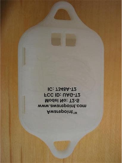
UAG-T2
Oct 02, 2007Tracking Tag for an Indoor Positioning System
Equipment Class
DTS - Digital Transmission System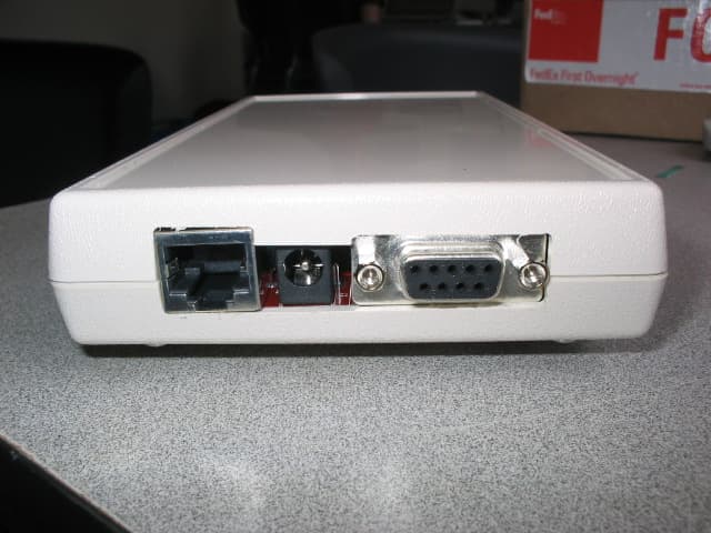
UAG-00000000B100
Jun 18, 2006Wireless Mesh Network Bridge
Equipment Class
DTS - Digital Transmission System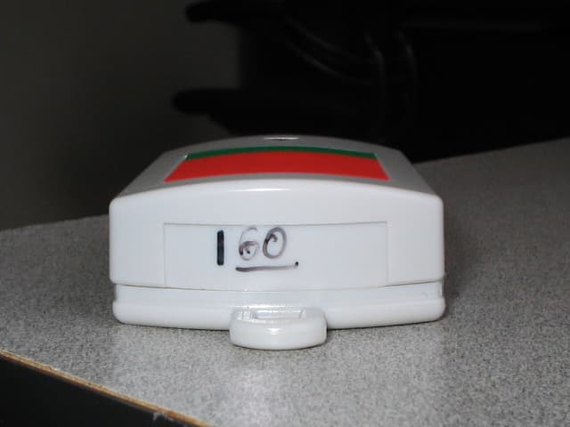
UAG-00000000T100
Jun 13, 2006Battery Powered Equipment Tracking Tag
Equipment Class
DTS - Digital Transmission System