UB9HL-2500FXHF 50 MHz LINEAR POWER AMPLIFIER
Tokyo Hy-Power Labs, Inc.
Click to zoom
Application Details
- Equipment Class
- AMP - Amplifier
- Date of Grant
- Jul 18, 2013
- Application Purpose
- Original Equipment
- Date of Application
- Jul 18, 2013
- Equipment Note
- HF 50 MHz LINEAR POWER AMPLIFIER
- Frequency Range
- 50.00000000 - 54.00000000
- Company
- Tokyo Hy-Power Labs, Inc.
- Country
- Japan
Documents & Files
Document Text
Text extracted from the exhibit documents filed with the FCC. Open a document above to read the original.
Users Manual
-0 - INSTRUCTION MANUAL HF ・ 50MHz LINEAR POWER AMPLIFIER POWEROPER. METER Pr VD ALC OFFSTBY BAND AUTO MAN’L ON AIR FAN ID PROT Pf/kW HF SOLID STATE LINEAR AMPLIFIER HL-2500FX MAN’L 1.8 3.5 7 10 14 18/21 24/28 50 Pr/VD/ID/ALC OUTPUT HI LO ANT A B ID 1.Introduction Thank you for purchasing the HL-2500FX. This compact and lightweight desktop HF linear power amplifier has a maximum input power of 2.9 kW. Our solid-state broadband power amp technology makes it the smallest and lightest in the industry. Typical output power is 1.5 kW PEP/SSB on HF (1kW on 50MHz) with the drive power of 85-90 W. The built-in band decoder will let you forget about the band setting when the amplifier is connected to your modern radio through such band data cables as ICOM CI-V, DC voltage (Yaesu and Elecraft K3), and RS-232C (Kenwood). These data cables are optional parts. The one that matches your radio should be purchased separately. 2. Cautions 2-1 Unpack the amplifier, check the fan guard at the rear panel fan to see if there is any damage caused by the physical shock during the transportation. Fan blades must be free to rotate when powered. The amplifier is cooled by forced airflow. Several inches of clearance on the top and the rear wall are necessary to allow for smooth air intake into the fan. Do not block the air vents on the top cover. 2-2 Keep the amplifier out of direct sunlight, in a cool dry environment. 2-3 Internal high voltages, (AC, DC and RF), are present at all times, ON AIR or OFF. Internal access should be limited to avoid injury. 2-4 Turn off the AC main power immediately upon any unusual sounds, sights or odors. Check the multimeter readings of Vd and Id, the fuses and all cable connections around the amplifier. Please notify the dealer or the factory of any problems. 2-5 For your safety, do not operate the amplifier without adequate grounding. A proper ground connection will result in peak performance and stability, in addition to reduced RF strays or noises. 2-6 To eliminate the RF interference to such home appliances as TV, FM radio, telephone sets, etc., -1 - it is recommended that clamp-on ferrite cores be inserted at both ends of the remote control cable, ALC cable, coaxial jumper cable, and antenna cables, as needed. Also, a common mode AC line filter (near the AC outlet), and in-line low pass filters on the antenna coaxial cable, (as necessary), are recommended. 2-7 The amplifier has fast acting sophisticated protection circuits controlled by the latest microprocessor technology. Please note, however, any such actions that cause the same fault to occur repeatedly, will lead to failure of the valuable final power FET transistors. Also note that the full power CW (or carrier) drive under the erroneous MANUAL BAND SETleads to the failure of the final power FET’s (See page 14, Section 10. Trial). In this sense, it is highly recommended that the amplifier is connected to the radio with Band Data Cable. 2-8 Before checking inside the amplifier, be sure to wait a few minutes for the high DC voltage to discharge (monitor Vd meter reading). The internal potentiometers for RF power detector, protection circuits, FET bias voltage circuit, etc., are precisely adjusted at the factory, and should not be altered. Doing so, would require readjustment with precision measuring instruments. 2-9 DC power supply selection is designed with wide AC line voltage technology and works with any voltage of 200V to 250V as well as 100V to 125V. 200V to 250V line, however, is recommended for the best stability and performance. Note that maximum output power is 1kW only, when 100V to 125V is connected. Prepare appropriate AC power cord plug that fits the outlet at your location. 2-10 Before powering on the amplifier, be sure to connect a dummy load (50 ohms, 1.5 kW min.) or a well-adjusted antenna to the output terminal. Operating without any load will cause extreme stress to the RF power FET’s, although protection circuits should work under critical conditions. 2-11 Required drive power is slightly less than 100 W to obtain the full 1.5 kW output. Do not attempt to operate with excessive drive from a high power transceiver. Transmitting high drive RF (over 100 W) into the amplifier will void the warranty. -2 - 2-12 Keep the aluminum heat sink and air openings free from dust and blockages. Periodic cleaning will prevent degraded cooling efficiency. 2-13 For long continuous operation in RTTY/FM modes, it is recommended you reduce the RF drive levels by 20% to 30% lower output than CW/SSB modes. 2-14 To prevent damage to the precision electronic components, avoid extreme physical shock to the amplifier. If factory service is required, the amplifier MUSTbe shipped using the original box and packaging materials. 3. Features 3-1 Our solid-state broadband design engineers worked to make the HL-2500KFX, the lightest and most compact 1.5 kW amplifier in the industry. This world-class compact 1.5 kW amplifier is the easiest to handle and operate. 3-2 The amplifier is equipped with a newly developed band decoder. The amplifier’s decoder changes bands automatically as the data signal is received from the associated HF transceiver’s frequency bands. 3-3The amplifier’s main PA section includes 6 high power MOS FET THP2933’s by Microsemi, resulting in 1.5 kW PEP (SSB max.). The amplifier’s broadband characteristics require no further tuning once the operating band is selected. 3-4 The amplifier allows operation in full break-in CW mode due to the use of the amplifier’s high- speed antenna relays (made by Panasonic). 3-5With the unique duct structure design and the powerful blower fan, the aluminum heat sink block for RF PA module (and other components), are effectively cooled. The fan’s quiet operation allows for even the weakest DX signals to be heard. -3 - 3-6 The amp utilizes an advanced 16 bit MPU (microprocessor) to run the various high speed protection circuits such as overdrive, high antenna SWR, DC overvoltage, band m…
Text truncated - open the document above for the full version.
Block Diagram
-37 - 14 Block Diagram and Explanation of Major Circuitry 14-A RF Amp Driving RF signal transmitted from the transceiver is lead to the ATT/ Limitter board via T/R-Assy unit, where there is 3dB attenuator as well as RF limiter. These circuitry properly levels the magnitude of RF signal and also instantly shuts down the input to protect the amplifier. There is a three port splitter located in this board that sprits a driving signal equally into three components, which are then fed to final PA module. PA module consists of three sets of wide band class AB1 linear amp. using THP2933 FET’s in the push-pull form. 500W is achieved per one basic amp. board. Then the three outputs from the PA module is sent to the combiner unit, where three 500W components are combined to become 1,500W. Operating status of three PA’s are strictly monitored in the combiner stage with regard to heat balancing of respective amps. Finally 1,500W of RF output is lead to LPF (low pass filter) unit, where harmonics and spurious signals are reduced to FCC rules. Filtered output signal is sent to T/R ASSY unit again and is lead to antenna terminal by way of antenna relay.
External Photos
1 H L - 2 5 0 0 F X H L - 2 5 0 0 F X D E T A I L P H O T O G R A P H S J u n e 1 3 , 2 0 1 3 T O K Y O H Y - P O W E R L A B S . , I N C . 2 H L - 2 5 0 0 F X O V E R A L L V I E W 3 H L - 2 5 0 0 F X F R O N T V I E W 4 H L - 2 5 0 0 F X R E A R V I E W 5 H L - 2 5 0 0 F X T O P V I E W 6 H L - 2 5 0 0 F X S I D E V I E W ( R I G H T ) S I D E V I E W ( L E F T ) 7 H L - 2 5 0 0 F X B O T T O M V I E W 8 H L - 2 5 0 0 F X L A B E L S A M P L E A N D S K E T C H O F L O C A T I O N R E A R P A N E L O V E R V I E W F C C I D L A B E L ( S A M P L E ) N A M E A N D R A T I N G
ID Label/Location Info
ANT BANT A INPUT ALC ADJALCSEND HF/50MHz Linear Amplifier Model HL-2500FX RF OUT : RF INPUT : 1.5kWmax 100Wmax S/NMade in Japan FOR AMATEUR RADIO USE ONLY AC90V FCC ID : UB9HL-2500FX TOKYO HY-POWER LABS.,INC. MADE IN JAPAN THIS DEVICE COMPLIES WITH FCC RULE PART xx. F K Y I CIV 1 2 3 FUSE FUSE AC IN 12V2A DC OUT REMOTE GND USB SERIAL CONT TUNER SELECT
Internal Photos
9 H L - 2 5 0 0 F X I N T E R N A L V I E W 1 0 H L - 2 5 0 0 F X H L 2 5 _ M T R _ P C S O 1 7 9 0 A S S Y M E T E R A S S Y 1 1 H L - 2 5 0 0 F X H L 2 5 0 0 _ A T T _ P C S O 1 8 9 4 A T T A N D D I S T R I B U T O R R F I N P U T 3 - P O R T O U T P U T 1 2 H L - 2 5 0 0 F X H L 2 5 0 0 _ C O M B _ P C S O 1 8 9 5 C O M B I N E R A S S Y P A F U S E 1 3 H L - 2 5 0 0 F X H L 2 5 0 0 _ C P U _ P C S O 1 8 9 9 C O N T R O L U N I T F R O N T P A N E L S W I T C H E S M A I N M P U 1 4 H L - 2 5 0 0 F X H L 2 5 0 0 _ D E T _ P C S O 1 8 9 8 T / R R E L A Y A N D D E T E C T O R A L C L E V E L A L C S E N D A N T B A N T A I N P U T F R O M F I L T E R T O A T T A S S Y O U T P U T R E L A Y A N T R E L A Y I N P U T R E L A Y 1 5 H L - 2 5 0 0 F X H L 2 5 0 0 _ D I S T _ P C S O 1 9 0 1 D C P O W E R D I S T R I B U T O R F O R S W I T C H I N G P O W E R S U P P L Y N O I S E F I L T E R R E L A Y A S S E M B L E D V I E W 1 6 H L - 2 5 0 0 F X H L 2 5 0 0 _ F I L _ P C S O 1 8 9 7 F I L T E R U N I T 1 7 H L - 2 5 0 0 F X H L 2 5 0 0 _ H V _ P C S O 1 9 1 7 H I G H V O L T A G E C O N V E R T E R F O R P I N A T T R E V E R S E B I A S S P A C E F O R C O S E L P O W E R S U P P L Y 1 8 H L - 2 5 0 0 F X H L 2 5 0 0 _ I N T E R F A C E _ P C S O 1 9 0 0 I N T E R F A C E A S S Y M O U N T E D O N R E A R P A N E L P A N E L S I D E V E W P A N E L R E A R V E W 1 9 H L - 2 5 0 0 F X H L 2 5 0 0 P A _ P C S O 1 8 9 6 P O W E R A M P A S S Y P A 1 P A 2 F I N A L M O S - F E T P A 3
Operational Description
-37 - 14 Block Diagram and Explanation of Major Circuitry 14-A RF Amp Driving RF signal transmitted from the transceiver is lead to the ATT/ Limitter board via T/R-Assy unit, where there is 3dB attenuator as well as RF limiter. These circuitry properly levels the magnitude of RF signal and also instantly shuts down the input to protect the amplifier. There is a three port splitter located in this board that sprits a driving signal equally into three components, which are then fed to final PA module. PA module consists of three sets of wide band class AB1 linear amp. using THP2933 FET’s in the push-pull form. 500W is achieved per one basic amp. board. Then the three outputs from the PA module is sent to the combiner unit, where three 500W components are combined to become 1,500W. Operating status of three PA’s are strictly monitored in the combiner stage with regard to heat balancing of respective amps. Finally 1,500W of RF output is lead to LPF (low pass filter) unit, where harmonics and spurious signals are reduced to FCC rules. Filtered output signal is sent to T/R ASSY unit again and is lead to antenna terminal by way of antenna relay. -38 - 14-B DC Power Supply AC power is received at the IEC socket i ntake and passes the line filter. There are safety fuses on both lines. There are control power supply and FET drain power supply . Start up is usually made by turning on and off of control power supply. DC 12V, 24V and 100V are available when control power supply is turned on, and are always outputted once the POWER is turned on. There are a magnet relay at primary side and DC ON/OFF function at secondary side. Depending on the operating condition, this power supply is turned on and off through the control circuit, and is provided in this power supply to meet IEC61000-3-2 harmonics regulation. 14 Block Diagram and Explanation of Major Circuitry 14-C Control Circuit Control circuit performs various control using m icro-processor PIC18F8722 chip. Also, basic interface meet the necessary rules and conditions using the specialized semiconductor devices.
Parts List/Tune Up Info
1 / 20 ■ PARTS LIST ■ Model : HL-2500FX GENERAL Reference/Symbol Parts Type/Model Description Quantity Manufacturer Vendor Remarks PS1,PS4,,,,,,, Switching Power Supply ADA1000_48_R ADA1000F-48-XTKHA 2 Cosel Special Specification P12,P13,P14,P15,P18,P19,,, Crimping Terminal 2-3 2-3 6 Nichifu P1,,,,,,,, Coax Plug BNC_P BNC_P 1 Toh-Conne P6,P7,P8,,,,,, Coax Plug BNC_P55 BNC_P55 3 Toh-Conne P2,P3,P4,P5,P9,P10,P11,P16,P34 Coax Plug SMB_P1.5 SMB_P1.5 9 Toh-Conne K1,,,,,,,, Micro Switch B V-21-3CR6 1 Omron J6,,,,,,,, Connector VLR6 VLR6 1 Nichiatsu J4,J5,,,,,,, Connector RCA_J RCA_J 2 Marushin-Musen C2,C3,,,,,,, AC Capacitor AC222 CS11-E2GA222MYGS 2 TDK C1,,,,,,,, Fixed Film Dielectric Capacitors QXP2G334 QXP2G334 1 Nichikon CT1,,,,,,,,,, Current Sensor HAS200-S HAS200-S 1 LEM Japan FAN1,,,,,,,,,, Cooling Fan 9GV1224P1H01(011) 9GV1224P1H01(011) 1 Sanyo Denki F1,F2,,,,,,,,, Fuse Holder F-70 F-70 2 Sato F3,F4,,,,,,,,, Fuse Holder 250V20A(35SF20) 250V20A(35SF20) 2 Hinode Electric P23,P30,,,,,,,,, Connector XG4M1031 XG4M1031 2 Omron P27,P29,P35,P36,P51,P58,,,,, Connector XG4M1631 XG4M1631 6 Omron P24,P43,P44,P45,P46,P48,P54,P60,P63,P73,P76 Connector EHR2 EHR2 11 Nichiatsu P62,P75,,,,,,,,, Connector J42FSC-02V-KX J42FSC-02V-KX 2 Nichiatsu P40,P41,,,,,,,,, Connector XG4M2631 XG4M2631 2 Omron P61,,,,,,,,,, Connector EHR3 EHR3 1 Nichiatsu J8,,,,,,,,,, Connector SMP03V SMP03V 1 Nichiatsu P65,P68,,,,,,,,, Connector 1-1123722-4 1-1123722-4 2 Taiko P25,P26,P32,P37,P38,P42,P49,P50,P59,, Connector EHR4 EHR4 9 Nichiatsu P56,,,,,,,,,, Connector MX4P MX4P 1 Molex P28,P53,,,,,,,,, Connector SMP04V SMP04V 2 Nichiatsu J9,,,,, Connector SMP404V SMP404V 1 Nichiatsu P22,P52,,,, Connector SMR04V SMR04V 2 Nichiatsu P66,P69,,,, Connector 1-1123722-5 1-1123722-5 2 Nichiatsu Revised : June 13, 2013 Designer : J. Shimada 2 / 20 ■ PARTS LIST ■ Model : HL-2500FX GENERAL Reference/Symbol Parts Type/Model Description Quantity Manufacturer Vendor Remarks Revised : June 13, 2013 Designer : J. Shimada P67,P70,,,, Connector EHR5 EHR5 2 Nichiatsu P64,P74,,,, Connector PHDR14VS PHDR14VS 2 Nichiatsu P17,P20,P21,P31,P57, Connector EHR7 EHR7 5 Nichiatsu P33,P39,P47,P55,P71,P72 Connector EHR8 EHR8 6 Nichiatsu PS2,,,,, Switching Power Supply LFA30-24 LFA30-24 1 Cosel PS3,,,,, Switching Power Supply LFA50-12 LFA50-12 1 Cosel LF1,,,,, Line Filter SUP-J15G-E SUP-J15G-E 1 Okaya ElectricIndustries L1,,,,, Common Mode Choke Coil L800 L800 1 THP R3,,,,, Metal Oxide Film Resistor 2W470k 2W470k 1 Takman R1,R2,,,, Metal-Film Resistor RN1k RN1k 2 KOA M1,,,,, Panel Meter L1356HK-1/SK6032-45 L1356HK-1/SK6032-45 1 Shinwa Same HL-2K M2,,,,, Panel Meter L1356HK-2/SK6032-46 L1356HK-2/SK6032-46 1 Shinwa Same HL-2K DISP1,,,,, LCD Module L1356SC2402A L1356SC2402A 1 Sunlike SW1,SW2,SW3,SW4,SW5 Rocker Switch DS850 DS850 5 Miyama VR1,,, Potentio Meter RV16_10kB RV16_10kB 1 Tokyo Cosmos 3 / 20 ■ PARTS LIST ■ Model : HL-2500FX METER UNIT Used by two combining. Reference/Symbol Parts Type/Model Description Quantity Manufacturer Vendor Remarks C1 Multi Layer Ceramic Capacitor RPE103 RPE103 1 Murata C2 Multi Layer Ceramic Capacitor RPE104 RPE104 1 Murata JP1 Connector S4B S4B 1 Nichiatsu PCB1 PCB PCS1790 PCS1790 1 Sanko Denki R1 Metal-Film Resistor RN1/8W100 RN1/8W100 1 KOA Revised : June 13, 2013 Designer : J. Shimada 4 / 20 ■ PARTS LIST ■ Model : HL-2500FX ATT UNIT Reference/Symbol Parts Type/Model Description Quantity Manufacturer Vendor Remarks ATT1,,,, Attenuator 100W3dB 100W3dB 1 Diconix(France) Adforest Q1,,,, MOSFET 2SK4021 2SK4021 1 Toshiba T1,,,, RF Transformer RiB16x32x16/D12A_ RiB16x32x16/D12A_ 1 THP JP1,,,, Connector B2B B2B 1 Nichiatsu T2,,,, RF Transformer T37-43_BFR10t0.3 T37-43_BFR10t0.3 1 THP J1,J2,J3,J4 Coaxial Connector SMB-P1.5 SMB-P1.5 4 Toh-Conne C7,,,, Chemical Capacitor 2kV18p 2kV18p 1 TDK C3,C4,,, Chemical Capacitor 2kV82p 2kV82p 2 TDK C1,,,, Chemical Capacitor 2kV12pF 2kV12pF 1 TDK C5,C6,C9,C10,C13 Chemical Capacitor CC630V104 GRM43DR72J104KW01L 5 Murata C12,,,, Chemical Capacitor RPE103 RPE132R103K50 1 Murata C14,,,, Chemical Capacitor RPE_CH_222 RPE2C1H222 1 Murata COAX1,COAX2,COAX3,, Coaxial Cable DFS014(25) DFS014(25) 3 Junkosha L3,,, Carbon Resistor 0OHM 0OHM 1 Takman L6,L7,L8,L9 Choke Coil CB20_100uH CB20_100uH 4 Shichinohe Tsushin L4,,, Choke Coil LC0089 LC0089 1 Shichinohe Tsushin C8,C11,, Chemical Capacitor 100V47u EKMG101ELL470 2 Nippon Chemi-Con C2,C15 Trimmer Capacitor TZ03Z100F169 TZ03Z100F169 2 Murata D6,,, Diode 1N4007 1N4007 1 Rectron D1,D2,, PIN Diode MA4P4006B MA4P4006B 2 MA-COM F1,,, Fuse LM16 LM16 1 Daito CommunicationApparatus JP2,,, Connector B4B B4B 1 Nichiatsu L1,,, Coil T50-12_5t T50-12_5t 1 THP L5,,, Coil T50-12-14t T50-12-14t 1 THP L2,,, Coil T50-12-3t T50-12-3t 1 THP FH1,,, Fuse Holder LM1H LM1H 1 Daito CommunicationApparatus Revised : June 13, 2013 Designer : J. Shimada 5 / 20 ■ PARTS LIST ■ Model : HL-2500FX ATT UNIT Reference/Symbol Parts Type/Model Description Quantity Manufacturer Vendor Remarks Revised : June 13, 2013 Designer : J. Shimada PCB1,,, PC Board PCSO1894 PCSO1894 1 Sanko Denki/Orion R9,,, Metal Oxide Film Resistor 1W4.7k 1 Takman R12,,, Carbon Resistor 1k 1 Takman R1,R2,R3 Metal Oxide Film Resistor 2W18 3 Takman R13,, Carbon Resistor 4.7k 1 Takman R8,, Metal Oxide Film Resistor 5W2.2k 1 Takman R10,, Metal Oxide Film Resistor 5W4.7k 1 Takman R5,R6, Metal-Film Resistor RN2W51 SN3DDCF51Ω 2 KOA R11,, Power Resistor(High Power) RNP10_39 RNP10_39 1 Nikkohm R4,, Power Resistor(High Power) RNP50UC_22ohm RNP50UC_22ohm 1 Nikkohm R7,, Power Resistor(High Power) RNP50_120ohm RNP50_120ohm 1 Nikkohm FC1,FC2,FC3 Ferrite Bead HF70RH8x15x4 HF70RH8x15x4 3 TDK D3,D4,D5 Zener Diode HZ33-2 HZ33-2 3 Renesas 6 / 20 ■ PARTS LIST ■ Model : HL-2500FX COMBINER UNIT Reference/Symbol Parts Type/Model Description Quantity Manufacturer Vendor Remarks TB1,TB2,TB3,TB4,TB5,TB6 Terminal Screw Y103 Y103 6 Morimatsu T1,,,,, RF Transformer RIB42x42x21_D12A RIB42x42x21_D12A 1 THP K1,,,,, Temperature Switch OHD5R_70 OHD5R_70 1 TOKIN…
Text truncated - open the document above for the full version.
Parts List/Tune Up Info
-13 - POWEROPER. METER Pr VDALC OFFSTBY BAND AUTO MAN’L ON AIR FAN ID PROT Pf/kW HF SOLID STATE LINEAR AMPLIFIER HL- 2500FX MAN’L 1.8 3.5 7 10 14 18/21 24/28 50 Pr/VD/ID/A LC OUTPUT HI LO ANT A B ID POWEROPER. METER Pr VDALC OFFSTBY BAND AUTO MAN’L ON AIR FAN ID PROT Pf/kW HF SOLID STATE LINEAR AMPLIFIER HL- 2500FX MAN’L 1.8 3.5 7 10 14 18/21 24/28 50 Pr/VD/ID/A LC OUTPUT HI LO ANT A B ID 9 Operation 9-A Quick Learning / About Status Modes 1) STBY (Stand-by) Mode 1.8MHz AUT-CIV ANT-A STBY Temp35C OUT_Hi POWEROPER. METER Pr VD ALC OFFSTBY BAND AUTO MAN’L ON AIR F AN I D PROT Pf/kW HF SOLID STATE LINEAR AMPLIFIER HL- 2500FX M AN’L 1.8 3 .5 7 10 1 4 1 8/21 2 4/28 5 0 Pr/VD/ID/A L C OUTPUT HI LO ANT A B I D This is a status when POWER switch is only turned on. RF path is in THRU (or by-pass), and DC supply to FET drain is shut down. You may change BAND and other settings at this state. 2) OPER (Operate) Mode 1.8MHz AUT-CIV ANT-A OPER Temp35C OUT_Hi POWEROPER. METER Pr V DALC OFFSTBY BAND AUTO MAN’L ON AIR FAN I D P ROT Pf/kW H F SOLID STATE LINEAR AMPLIFIER HL- 2500FX M AN’L 1.8 3 .5 7 10 14 18/21 24/28 50 Pr/VD/ID/A L C OUTPUT HI LO ANT A B ID This is a status when POWER switch is turned on, and OPER/STBY switch is tuned to OPER. RF path is in THRU, and amp is turned into ON-AIR, as the radio’s PTT is switched on. You may change BAND setting at this state. 3) ON-AIR(On-Air) Mode 1.8MHz AUT-CIV ANT-A ONAR Temp35C OUT_Hi This is a status when transceiver’s PTT is switched on, while POWER is turned on and OPER/STBY switch is turned to OPER. The amp is ready to amplify the driving signal from the transceiver. You may not change BAND and other setting at this state. 送信 4) PROT (Protection) Mode 1.8MHz AUT-CIV ANT-A PROT Over Heat This is a status when PROTECTION circuit has tripped to shut off the amplifier. RF path becomes THRU, and internal circuitry may be shut down according to kinds of protections. Detailed explanation will follow. 送信 CAUTION For your safety, the amp can not start up, if POWER switch is at OPER.Display below will appear. PSE STBY OPERSW! Turn to STBY once and turn to OPER again for reset. There are four operation status modes of STBY, OPER, ON- AIR, and PROT. -14 - 9-B Quick Learning / About Basic Signs On LCD and LED Lamps 1) CB Band Inhibit T he amp will shut down the transmission when driving signal of 26,000 through 27,999 (CB band) is detected due to FCC rule. When combining with ICOM and Kenwood radios, frequency data of operation is passed to CPU, even at RX state, to prohibit the transmission. EXCDMHz Is signed on LCD. (Freq. exceeded) EXCDMHz AUT-CIV ANT-A STBY Temp35C OUT_Hi With ICOM, KENWOOD 28 MHz AUT-YAE ANT-A PROT INHIBIT FREQ With YAESU, Manual Band Set, Frequency Count Band Set 2) OPER. MODE Switch The amp will be shut down, if POWER switch is turned on, while OPER/STBY is set at OPER. PSE STBY OPERSW! To reset, switch OPER. off and on. This is to avoid unintended sudden transmission, for your safety PSE STBY OPERSW! LCD message 4) ID Lamp I D lamp lights when FET drain currents exceeds 55A, and is a kind of peak current indicator. It is not a problem, if it lights only at a voice peak (SSB). ON AIR FAN ID PROT 5) FAN Lamp The cooling speed changes in proportion to the variation of internal temperature. As the ONAIR time gets longer , It is normal if fan noise sounds louder and FAN lamp to light brighter. ON AIR FAN ID PROT 3) TRACK Sign 3.5 MHz AUT-CIV ANT-A TRCK Temp35C OUT_Hi TRACK (Tracking) sign will appear, when the BAND changes , for a short period of 0.2 sec. This indicates that band frequency data is being sent over to combined auto tuner. When with Yaesu Radio, and with manual band set and freq. count band set methods, the amp transmission will be shut down when at TX PROT INHIBIT FREQ will appear on LCD. EEE E -15 - POWEROPER. METER Pr VDALC OFFSTBY BAND AUTO MAN’L ON AIR FAN ID PROT Pf/kW HF SOLID STATE LINEAR AMPLIFIER HL-2500FX MAN’L 1.8 3.5 7 10 14 18/21 24/28 50 Pr/VD/ID/ALC OUTPUT HI LO ANT A B ID POWEROPER. METER Pr VDALC OFFSTBY B AND A UTO MAN’L O N AIR F AN I D P ROT P f/kW HF SOLID STATE LINEAR AMPLIFIER HL-2500FX MAN’L 1.8 3.5 7 10 1 4 18/21 24/28 50 Pr/VD/ID/ALC OUTPUT H I LO ANT A B ID 9-C Quick Learning / About TX Trial We recommend for you to run a trial operation, at first, under the Manual Band Set mode (without band data cable connected to radio). With this trial, you can check if antenna, cables, and AC power line are in a proper condition. In case you encounter any trouble under Auto Band Set connection, later, you could return to this trial mode to see where the cause of trouble is. Front Panel ・ POWER=OFF ・ OPER=OFF (STBY) ・ OUTPUT=HI ・ BAND=MANU‘L ・ (Others=Any as needed) Rear Panel ・ ALC=C.C.W (Fully counter clock-wise) ・ Select=Any position Any position F USE F USE A NT AANT B I NPUT ALC ADJ A LC S END T UNER SELECT AC IN F USE FUSE R EMOTE D C OUT 12V1A CONT SERIAL U SB GND Turn the POWER on and the amp will start to execute initial self-check, Following messages will appear on LCD until status reaches normal operation mode. TOKYO HY-POWER HL -2500FX V1.00 PLEASE WAIT CHECKING CONDITIONS ACV is 198V Normal MODE Complete Initial Set-Up 1 sec 1 sec 1 sec 1.8MHz Manual ANT-A STBY Temp35C OUT Hi Initial Sign Checking Checking Over Operation Ready After turning POWER switch on, MPU chip will check to see if AC line voltage is usable for the amplifier. NOTE 1) Setting Before Power ON 2) Powering ON Signs Transceiver ・ Mode=CW (or RTTY) ・ RF POWER LEVEL=Minimal -16 - POWEROPER. METER Pr VDALC O FFSTBY BAND A UTO M AN’L ON AIR F AN ID PROT P f/kW H F SOLID STATE LINEAR AMPLIFIER HL-2500FX MAN’L 1 .8 3 .5 7 1 0 14 18/21 2 4/28 50 Pr/VD/ID/ALC OUTPUT H I L O ANT A B ID Set the freq. BAND as desired for both transceiver and HL-2500FX. ( Ex.: 14MHz) 3 ) Band Setting 1 4MHz 設定 9-C Quick Learning / About TX Trial NOTICE When the BAND switch is turned under Man’l Set mode, selected BAND will shift as follows: ・ If turned clock-wise, B…
Text truncated - open the document above for the full version.
Schematics
SHEETDATEDESIGN DRAWING_No.TITLE +24V +24V GND GND +24V +24V GND GND -12V RTN-12V LINE_VOLT LINE_VOLT_G LFA_24_PRI+ LFA_24_PRI- LFA_SEC_5 LFA_SEC_2 LFA_SEC_0 HV HV_RTN TOKYO HY-POWER LABS,INC. HL2500_HV.dcd HIGH VOLTAGE UNIT AUG. 20, 2012 HL-2500FX T. OHSAWA JP1 B4B 4 3 2 1 JP3 B2B 1 2 JP4 B2B 1 2 JP5 B3B 3 2 1 JP2 B8B 1 2 3 4 5 6 7 8 D5 UF4007 C2 50V100u + C3 200V22u + U1 79L12 2 I 1 G 3 O C4 50V100u + C5 25V22u + R5 1/2W1k R6 1/2W1k D7 1N5711 D8 1S2076 R3 1W47k R2 2W1k D3 UF4007 D2 UF4007 D1 UF4007 D4 TPL430B-TB R4 2.2k D6 TPL230B-TB C6 50V2.2u + D9 TPL930B-TB C1 ECQE1475KF R1 1W22 PCB1 PCSO1917 PCB
Schematics
SHEETDATEDESIGN DRAWING_No.TITLE HL-2500FX TOKYO HY-POWER HL2500_ATT.dcd 100W3dB 100V+100V GND +12V GND SHUT_DN GND 1T 3T AUG. 17, 2012T. OHSAWA ATT UNIT JUMPER REVISED : OCT. 17, 2012 D3 HZ33-2 D4 HZ33-2 D5 HZ33-2 C11 100V47u + R10 5W4.7k R8 5W2.2k R13 4.7k D6 1N4007 C8 100V47u + R9 1W4.7k C9 CC630V104 C10 CC630V104 C12 RPE103 L4 LC0089 FH1 LM1H F1 LM16 ATT1 16-3298 P1P2 C5 CC630V104 R11 RNP10_39 C6 CC630V104 L8 CB20_100uH L3 0OHM C13 CC630V104 Q1 2SK4021 C14 RPE_CH_222 JP1 B2B 2 1 J1 SMB-RPC D2 MA4P4006B D1 MA4P4006B L6 CB20_100uH L7 CB20_100uH L9 CB20_100uH +12V +12V R12 1k JP2 B4B 4 3 2 1 C4 2kV82p R4 RNP50UC_22ohm R5 RN2W51 R6 RN2W51 L5 T50-12-14t R7 RNP50_120ohm FC2 HF70RH8x15x4 FC3 HF70RH8x15x4 C3 2kV82p FC1 HF70RH8x15x4 COAX1 DFS014(25) COAX2 DFS014(25) COAX3 DFS014(25) R3 2W18 R2 2W18 R1 2W18 L2 T50-12-3t L1 T50-12_5t C2 TZ03Z100F169 C7 2kV18p C15 TZ03Z100F169 C1 2kV12pF T1 RiB16x32x16/D12A_ J3 SMB-RPC J4 SMB-RPC J2 SMB-RPC T2 T37-43_BFR10t0.3 3 12 4 PCB1 PCSO1894 PCB
Schematics
SHEETDATEDESIGN DRAWING_No.TITLE COM_OH1 COM_OH2 HL2500_COMB.dcd HL-2500FX TOKYO HY-POWER COM_OH2 COM_OH1COMB_OH1 COMB_OH2 LOAD50+ LOAD50- GND COMB_OUT COMB_OUT_G VDD1 VDD2 VDD3 RTN1 RTN2 RTN3 COMBINER AUG. 17, 2012T. OHSAWA COMBINER UNIT REVISED : OCT. 10, 2012 L1 ID12_4t_PEW2 K1 OHD5R_70 C2 RPE103 C1 RPE103 R1 RNP50UC18ohm R2 RNP50UC18ohm R3 RNP50UC18ohm COAX4 DFS25ohm COAX2 DFS25ohm COAX1 DFS50ohm_43cm COAX3 DFS50ohm_43cm COAX5 DFS50ohm_43cm FC6 RIB10x20x15_D12A FC4 RIB10x20x15_D12A FC2 RIB10x20x15_D12A T1 RIB42x42x21_D12A COAX6 DFS25ohm TB3 Y103 TB4 Y103 TB1 Y103 TB2 Y103 K2B G2RL_1b_DC12V TB5 Y103 TB6 Y103 C4 RPE103 K2A G2RL_1b_DC12V D1 1N4002 JP1 B7B 1 2 3 4 5 6 7 C5 RPE103 U1B TLP521 3 4 F2 1197_20A_58V FH2 FHA040-01 R7 1/2W4.7k F3 1197_20A_58V FH3 FHA040-01 R9 1/2W4.7k FB1 HF70RH8X15X4 C8 RPE105 FB2 HF70RH8X15X4 FB3 HF70RH8X15X4 C10 RPE105 FB4 HF70RH8X15X4 FB5 HF70RH8X15X4 C12 RPE105 FB6 HF70RH8X15X4 TP2 Val TP1 Val TP3 Val TP4 Val TP5 Val TP6 Val C11 100V47u + C9 100V47u + C7 100V47u + FC3 TRB20x10x10_D12Ax6 FC5 TRB20x10x10_D12Ax6 FC1 TRB20x10x10_D12Ax6 R5 1/2W4.7k F1 1197_20A_58V FH1 FHA040-01 C6 RPE104 R4 2.2k U1A TLP521 21 JP2 B6BVL 6 3 5 2 4 1 C3 2kV12p R6 1W4.7k R8 1W4.7k R10 1W4.7k D2 TPL230BTB D3 TPL230BTB D4 TPL230BTB PCB1 PCSO1897 PCB
Schematics
SHEETDATEDESIGN DRAWING_No.TITLE CE2 S_CLK S_DATA CE1 S_CLK S_DATA ABS0 ABS1 ABS2 ABS3 BSW7 BSW6 BSW0 BSW1 BSW2 BSW3 BSW4 BSW5 TXD1 RXD1 TXD2 RXD2 TD2 RD2 TD1 RD1 CIV-T CIV-R USB_TD1 USB_RD1 BDY3 BDY0 BDY1 BDY2 232C_RD2 232C_RD1 232C_TD2 232C_TD1 TEMP TEMP_G GND +5V GND +12V LOAD50- FUSEB1 OH1 OH2 BIAS_EN SHUT_DN ANT1/ANT2 FUSEB1 FUSEB2 FUSEB3 BIAS_EN COMB_OH LOAD50-CPU TEMP_CPU_ TEMP_FAN T/R_RELAY 1.8M 10M 3.5M 7M 18/21M 24/28M 14M 50M COMB_OH1 COMB_OH2 OH1 DET_AND_T/R +12V 1.8M 10M 3.5M 7M 18/21M 24/28M 14M 50M +12V 1.8M 10M 3.5M 7M 18/21M 24/28M 14M 50M FILTER_UNIT GND T/R_RELAY 12V GND PWM +24V TACHO ANT1/ANT2 SEND1 24V_GND Pf Pr ALC_G ALC_OUT ALC_G ALC_VR ALC+10V T/R_RELAY 12V GND PWM +24V TACHO ANT1/ANT2 SEND1 24V_GND Pf Pr PDR ALC_G ALC_OUT ALC_G ALC_VR ALC+10V GND +5V GND RS E R/W CONT DB7 DB4 DB5 TOKYO HY-POWER HL2500_CPU.dcd HL-2500FX RS E DB5 DB4 DB7 MCLR +5V GND AN9 SEND1 SEND2 TEMP_FAN TACHO PWM BAND_SW FAN_TEST PWM_MON RJ7 RJ0 RJ1 RJ2 RJ3 RJ4 RJ5 RJ6 Pf_CPU Pr_CPU VDD_CPU ID_CPU TUNER_FREQ PCG PCD VDD_SEL2 TD1 RD1 CE1 CE2 S_CLK S_DATA COMB_OH FUSBLOW1 TX_INH OUT VDDON_CPU VDD_SEL1 AN_ICOM_CPU TEMP_CPU_ RD2 DB4 DB5 DB7 RS E TD2 MCLR TUNER_EVENT ANT_1/2_OUT OPER_SW HI/LO_SW AT_BAND_SW ANT1/ANT2_SW CROWBER PROT_LAMP LOAD50-CPU PWM_MON 1.8M 10M 3.5M 7M 18/21M 24/28M 14M 50M PROT OH1 FCC RJ7 RJ2 RJ3 RJ4 RJ5 RJ6 AN9 FAN_TEST GND RESET VDD MCLR FCC RF SAMPLE U4 RF_CICUITRY 3 LED- LED+ NC NC LINE_VOLT_CPU DC_ON_ANS +12V GND +12V GND PA_UNIT Pf Pr PDR CT_OUT VDD Pf_CPU Pr_CPU ID_CPU PDR_MTR Pf_MTR Pr_MTR VDD_MTR ID_MTR PDR_MTR Pf_MTR Pf_MTR Pr_MTR ALC+10V ALC_VR ALC_G ALC_OUT AN-IC AN-IC G AN_ICOM_CPU Pr_MTR ID_MTR MTR1+ MTR1- LAMP1+ LAMP1- MTR2+ MTR2- LAMP2+ LAMP2- METER SEL VDD_CPU VDD_MTR LINE_VOLT_CPU Pr_MTR ID_MTR PROT_LAMP VDD WAKE_UP+ WAKE_UP- ADA_LINE_ON- VDD_ON+ VDD_ON- VDD+ VDD- +12V GND AC_ON_ANS- VDD_ON_ANS- WAKE_UP+ WAKE_UP- VDD_L/H TURBO VDDON_CPU ADA_LINE_ON+ VDD_ON_ANS+ AC_ON_ANS+ CT_OUT +12V -12V GND +12V -12V GND CT_OUT LINE_VOLT_G RTN-12V -12V GND GND +24V +24V VDD_SEL2 VDD_L/H TURBO INTER-FACE +5V +12V GND GND EVENT FREQ ABS0 ABS1 ABS2 ABS3 BDY0 BDY1 BDY2 BDY3 CIV-T CIV-R SEND2 232C_RD2 232C_TD2 232C_RD1 232C_TD1 USB_TD1 USB_RD1 AN-IC AN-IC G +5V GND +12V GND GND EVENT FREQ ABS0 ABS1 ABS2 ABS3 BDY0 BDY1 BDY2 BDY3 CIV-T CIV-R SEND2 232C_RD2 232C_TD2 232C_RD1 232C_TD1 USB_TD1 USB_RD1 AN-IC AN-IC G VDD_SEL1 DC_ON_ANS AC_ON_ANS POWER_SUPPLY BIAS_EN TX_INH OUT ANT_1/2_OUT +12V GND LINE_VOLT LINE_VOLT T/R_CPU AC_ON_ANS PDR PDR_CPU PDR_CPU SHUT_DN CROWBER SHUT_DN PROT PGD PGC PGD PGC FAN_FAIL FAN_FAIL OPER_SW HI/LO_SW AT_BAND_SW GND GND GND AT_BAND_SW ANT1/ANT2_SW GND T/R_RELAY ANT1/ANT2_SW PANEL_SW REMOTE_CONT WAKE_UP+ WAKE_UP- WAKE_UP+ WAKE_UP- OPER_EXT GND OPER_SW HI/LO_SW PROT_LAMP POWER_LAMP ID_LAMP ID_LAMP MCLR T/R_CPU LINE_ON_CPU LINE_ON_CPU UTILITY SET SW_1 SET SW_1 DB6 DB6DB6 INTERNAL SETTING SWITCH AUG. 17, 2012T. OHSAWA CPU UNIT CROWBAR ADJUSTMENT SWITCH DELAY TIME LCD_DISPLAY REVISED : NOV. 15, 2012 C7 50V10u + C20 50V10u + C6 RPE105 C3 RPE105 +5V C4 RPE105 C5 RPE105 U2 MAX232 16 VCC 2 V+ 6 V- 15 GND 14 T1o 7 T2o 13 R1i 8 R2i 9 R2o 12 R1o 10 T2i 11 T1i 5 C2- 4 C2+ 3 C1- 1 C1+ R10 100 R8 100 R9 100 R7 100 C2 RPE105 U3 NJU3754 1 P0 2 P1 3 P2 4 P3 5 P4 6 P5 7 P6 9 P7 10 P8 11 P9 12 P10 8 GND 16 VDD 13 SO 14 CLK 15 CE +5V+12V +12V JP17 B8B 1 2 3 4 5 6 7 8 U10 TD62083AP 1 I1 2 I2 3 I3 4 I4 5 I5 6 I6 7 I7 8 I8 9 GND 10 COM 11 Q8 12 Q7 13 Q6 14 Q5 15 Q4 16…
Text truncated - open the document above for the full version.
Contact Information
Applicant
Nobuki Wakabayashi(Mgr.)
Test Firm
Timco Engineering, Inc.Bruno Clavier
Technical Specifications
| # | Rule Parts | Frequency Range | Power Output | Emission | Tolerance |
|---|---|---|---|---|---|
| 2 | 97 | 50 MHz - 54 MHz | 1000 W | J3E | Amp |
Other Applications from Tokyo Hy-Power Labs, Inc.

UB9HL-355VKX
May 09, 2013VHF AMATEUR RADIO AMPLIFIER
Equipment Class
AMP - Amplifier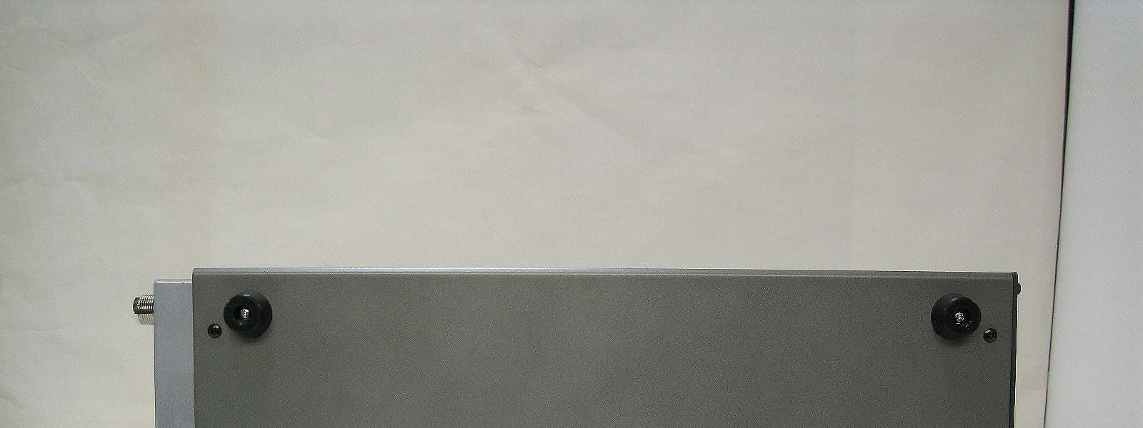
UB9HL-550FX
May 09, 2010550W HF LINEAR AMPLIFIER
Equipment Class
AMP - Amplifier
UB9HL-12KFX
Jul 08, 2007HIGH POWER AMPLIFIER
Equipment Class
AMP - Amplifier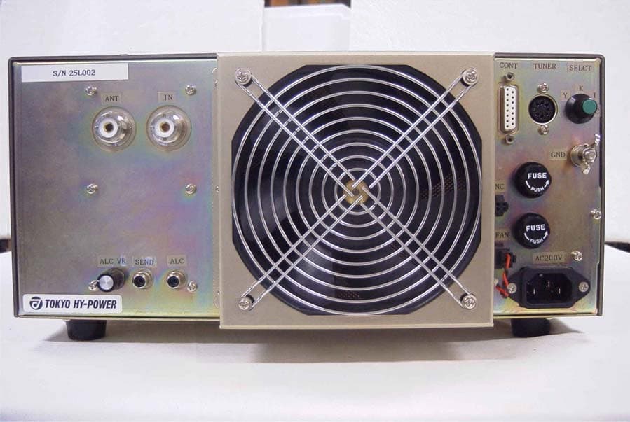
UB9HL-25KFX
Jul 02, 2007High Power Amplifier
Equipment Class
AMP - Amplifier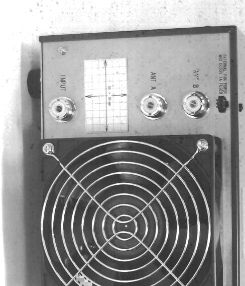
UB9HL-15KFX
Jun 18, 2006LINEAR AMP
Equipment Class
AMP - Amplifier