UB9HL-550FX550W HF LINEAR AMPLIFIER
Tokyo Hy-Power Labs, Inc.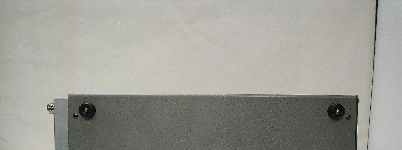
Click to zoom
Application Details
- Equipment Class
- AMP - Amplifier
- Date of Grant
- May 09, 2010
- Application Purpose
- Original Equipment
- Date of Application
- May 09, 2010
- Equipment Note
- 550W HF LINEAR AMPLIFIER
- Frequency Range
- 50.00000000 - 54.00000000
- Company
- Tokyo Hy-Power Labs, Inc.
- Country
- Japan
Documents & Files
Document Text
Text extracted from the exhibit documents filed with the FCC. Open a document above to read the original.
Users Manual
Users Manual Solid-State HF/50MHz Band 550W Linear Power Amplifier Model HL-550 FX 1 1. Introduction Thank you for purchasing the HL-550FX. This compact and lightweight desktop HF linear power amplifier has a maximum input power of 1.2kW. Our solid-state broadband power amp technology makes it the smallest and lightest in the industry in its class. Typical output power is 550W (SSB, CW) with the drive power of 65-90W. It is best suited for the DX-pedition use due to its light and compact design. 2. Cautions 2-1 The amplifier is cooled by forced airflow. Several inches of clearance on the top and the rear wall are necessary to allow for smooth air intake into the fan. Do not block the air vents on the top cover. 2-2 Keep the amplifier out of direct sunlight, in a cool dry environment. 2-3 Internal high voltages (AC, DC and RF), are present at all times, ON AIR or OFF. Internal access should be limited to avoid injury. 2-4 Turn off the AC main power immediately upon any unusual sounds, sights, or odors. Check the multimeter readings of Vd and Id, the fuses and all cable connections around the amplifier. Please notify the dealer or the factory of any problems. 2-5 For your safety, do not operate the amplifier without adequate grounding. A proper ground connection will result in peak performance and stability, in addition to reduced RF strays or noises. 2-6 To eliminate the RF interference to such home appliances as TV, FM radio, telephone sets, and etc., it is recommended that clamp-on ferrite cores be inserted at both ends of the remote control cable, ALC cable, coaxial jumper cable, and antenna cables, as needed. Also, a common mode AC line filter (near the AC outlet), and in-line low pass filters on the antenna coaxial cable (as necessary), are recommended. 2 2-7 The amplifier has fast acting sophisticated protection circuits. Please note, however, any such actions that cause the same fault to occur repeatedly, will lead to failure of the valuable final power FET transistors. 2-8 Before checking inside the amplifier, be sure to wait a few minutes for the high DC voltage to discharge (monitor Vd meter reading). The potentiometers for RF power detector, protection circuits, FET bias voltage circuit, etc., are precisely adjusted at the factory, and should not be altered. Doing so, would require readjustment with precision measuring instruments. 2-9 The DC power supply section consists of most efficient and sophisticated switching mode circuit. It accepts the wide AC line voltages ranging from AC 100V up to 260V. Since the line voltage is detected and selected automatically, you do not have to worry about the tap change of internal power transformer whichever country you will travel. Be sure to verify capacity of AC line fuse before you plug the AC power cord into the outlet. 2-10 Before starting the amplifier, be sure to connect a dummy load (50 ohms, 550W min.) or a well-adjusted antenna to the output terminal. Operating without any load will cause extreme stress to the RF power FET’s, although protection circuits should work under critical conditions. 2-11 Required drive power is slightly less than 100W to obtain the full 550W output. Do not attempt to operate with excessive drive from a high power transceiver. 2-12 Keep the aluminum heat sink and air openings free from dust and blockages. Periodic cleaning will prevent degraded cooling efficiency. 2-13 For long continuous operation in RTTY/FM modes, it is recommended that you reduce the RF drive levels by 20% to 30% lower output than CW/SSB modes. 2-14 To prevent damage to the precision electronic components, avoid extreme physical shock to the amplifier. If factory service is required, the amplifier should be shipped using the original box and packing materials. 3 3. Features 3-1 Our solid-state broadband design engineers worked to make the HL-550FX, the lightest and most compact 550W out portable HF/50MHz amplifier in the industry. This world-class compact 550W HF amplifier is the easiest to handle and operate anywhere in the world. 3-2 The amplifier’s main PA section includes 4 high power MOS FET VRF150, resulting in 550W (SSB/CW max.) on HF and 50MHz bands. The amplifier’s broadband characteristics require no further tuning once the operating band is selected. 3-3 The amplifier allows operation in full break-in CW mode due to the use of the amplifier’s high-speed antenna relays (made by Panasonic). 3-4 With the unique duct structure design and the powerful blower fan, the aluminum heat sink block for RF PA module (and other components), are effectively cooled. The fan’s quiet operation allows for even the weakest DX signals to be heard. 3-5 The amp utilizes a sophisticated circuit to run the various high speed protection circuits such as overdrive, high antenna SWR, DC overvoltage, band miss-set etc. 3-6 This amplifier is compatible with wide AC line voltage ranging from AC 100V to 260V. Although AC line voltage is automatically selected, be sure to install proper fuse into AC line fuse holder. 3-7 For the safety of the operator, an Interlock system is employed. The AC power is shut down if the top cover is removed, and the automated safety interlock is activated. 3-8 An analog multimeter allows the operator to monitor Pf (Forward output power), Pr (Reflected power), Vd (Drain voltage of power FET), Id (Drain current) etc. 4 4. Specifications Frequency Band 1.8~50 MHz all amateur bands including WARC bands Mode SSB, CW (RTTY) RF Drive 65~90W typ. (100W max.) Output Power 550W typ. (RTTY 400W max.) Drain Voltage 42V Drain Current 30A max. Input Impedance 50Ω (unbalanced) Output Impedance 50Ω (unbalanced) Final Transistor VRF150 x 4 Circuit Class AB parallel push-pull Cooling Method Forced Air Cooling Output Power Pf 1kW Reflected Power Pr 100W Drain Voltage Vd 60V Multi-meter (F.S.) Drain Current Id 50A Input/Output Connectors UHF SO-239 AC 200~260V, 50/60Hz 7.5A max. AC Power AC 100~130V, 50/60Hz 15A max. AC Consumption 1.3kVA max. w…
Text truncated - open the document above for the full version.
Cover Letter(s)
Model HL-550FX Explanation on Band Inhibit Circuit (To prohibit 26.028.0 MHz) Drive signal from the transceiver is, at first, received by the (RF) DET UNIT PC1821 and then transferred to PCS1733, FREQ. DETECTOR CIRCUIT. The signal is divided by sixteen (16) through the prescaler IC1, TD7101F. The resulting signal is sent to the IC2, PIC micro processor, where the signal frequency is counted If the drive signal is judged to fall in the band width of 26.0 to 28.0 MHz, IC2 issues the command to open the relay RL1, of which contacts are in series with the STAND-BY (STBY/OPER.) control circuit, as is shown around T/R pin of PC1818, CONT’L UNIT and STBY, RCA-Jack located at the rear panel of the amp. Once the STAND-BY control circuit becomes open, the amp keeps stand-by mode and amplifier gain is nil, even if it is driven by out of amateur band signals between 26.0 and 28.0 MHz.
External Photos
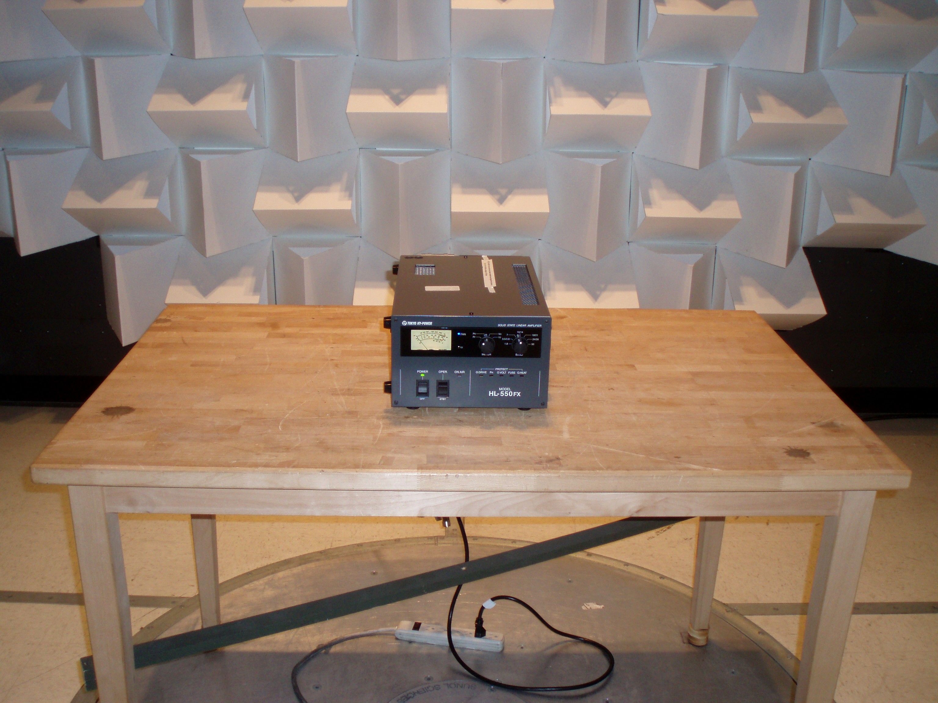
Model: HL-550FX / FCC Test Documents B. Photographs B. PhotographsB. Photographs B. Photographs <FRONT VIEW> <REAR VIEW> Model: HL-550FX / FCC Test Documents <TOP VIEW> <BOTTOM VIEW> Model: HL-550FX / FCC Test Documents <SIDE VIEW (RIGHT)> <SIDE VIEW (LEFT)>
ID Label/Location Info
Model: HL-550FX / FCC Test Documents C. Label Sample and Sketch of Location <Rear Panel>
Internal Photos
18 MAIN SW POWER SUPPLY (ADA1000F48) MAIN SW POWER SUPPLY (ADA1000F48) MAIN SW POWER SUPPLY (ADA1000F48) MAIN SW POWER SUPPLY (ADA1000F48) SUB SW POWER SUPPLY(KWD15-1212) SUB SW POWER SUPPLY(KWD15-1212)SUB SW POWER SUPPLY(KWD15-1212) SUB SW POWER SUPPLY(KWD15-1212) LPF UNIT(PC1817) LPF UNIT(PC1817)LPF UNIT(PC1817) LPF UNIT(PC1817) METER METERMETER METER FUSE(F1,F2) FUSE(F1,F2)FUSE(F1,F2) FUSE(F1,F2) DET UNIT DET UNITDET UNIT DET UNIT (PC1821) FAN FANFAN FAN F DET UNIT(PCS1733) F DET UNIT(PCS1733)F DET UNIT(PCS1733) F DET UNIT(PCS1733) PA UNIT(PC1662V) PA UNIT(PC1662V)PA UNIT(PC1662V) PA UNIT(PC1662V) CONT UNIT(PC1818) CONT UNIT(PC1818)CONT UNIT(PC1818) CONT UNIT(PC1818) TOP VIEW (DETAILED) 19 <TOP VIEW> <LEFT SIDE VIEW> <RIGHT SIDE VIEW> TOP VIEW & SIDE VIEW 20 J203J202(RF OUT)J201(RF IN) VR205(BIAS REF) VR202/VR201VR204/VR203 F201(MINI FUSE 1A) H HH HI II IL LL LO OO O ( (( (V VV VR RR R2 22 20 00 01 11 1~ ~~ ~V VV VR RR R2 22 20 00 04 44 4) )) ) F FF FE EE ET TT T B BB BI II IA AA AS SS S A AA AD DD DJ JJ J H HH HI II I L LL LO OO O PA UNIT (PC1662V) 21 PC1817 LPF PCB PC1817 LPF PCBPC1817 LPF PCB PC1817 LPF PCBPC1817 LPF PCB COPPER SIDE PC1817 LPF PCB COPPER SIDEPC1817 LPF PCB COPPER SIDE PC1817 LPF PCB COPPER SIDE J301J302 J303 PC1819 SUB AC PCB PC1819 SUB AC PCBPC1819 SUB AC PCB PC1819 SUB AC PCBPC1819 SUB AC PCB COPPER SIDE PC1819 SUB AC PCB COPPER SIDEPC1819 SUB AC PCB COPPER SIDE PC1819 SUB AC PCB COPPER SIDE F301J302 L801 KWD15-1212 LPF UNIT(PC1817) & SUB AC UNIT(PC1819) 22 PC000 LED PCB PC000 LED PCBPC000 LED PCB PC000 LED PCB PC000 LED PCB COPPER SIDE PC000 LED PCB COPPER SIDEPC000 LED PCB COPPER SIDE PC000 LED PCB COPPER SIDE PCS1733 F DET UNIT COPPER SIDE PCS1733 F DET UNIT COPPER SIDEPCS1733 F DET UNIT COPPER SIDE PCS1733 F DET UNIT COPPER SIDE PC1821 DET UNIT PC1821 DET UNITPC1821 DET UNIT PC1821 DET UNIT PCS1733 F DET UNIT PCS1733 F DET UNITPCS1733 F DET UNIT PCS1733 F DET UNIT PC1821 DET UNIT COPPER SIDE PC1821 DET UNIT COPPER SIDEPC1821 DET UNIT COPPER SIDE PC1821 DET UNIT COPPER SIDE FREQUENCY DETECTOR UNIT(PCS1733) & RF POWER DETECTOR UNIT(PC1821) 23 PC1818 CONT UNIT PC1818 CONT UNITPC1818 CONT UNIT PC1818 CONT UNIT IC103 C102 IC101 IC108 PC1818 CONT UNIT COPPER SIDE PC1818 CONT UNIT COPPER SIDEPC1818 CONT UNIT COPPER SIDE PC1818 CONT UNIT COPPER SIDE SW102SW101 CONTROL UNIT (PC1818)
Operational Description
Model HL-550FX-Theory of Operation(How It Works/ RF Signal Flow)- 1/2 Model HL-550FX Theory of Operation (How It Works/ RF Signal Flow) When the amplifier is in a stand-by (STBY) mode, gate bias (voltage) to the final FET’s are cut off. Also input (TX) relay and output (ANT) relay are free(open) from the amplifier. Therefore the signals from the transceiver and/or from the antenna will all by-pass the amplifier. (By-Pass/ Stand-By Mode) When the amplifier is in an OPER.(operate) mode and keyed by the transceiver, forward gate bias is applied to the final power FET’s and at the same time input and output relays are closed at the IN and OUT terminals of the amplifier. Consequently the amplifier is ready to work with the designed amplification gain. RF Drive signal from the transceiver reaches RF IN (J504) of DET (Detector) Unit, PC1821, where input power level is measured. If the in drive power is over 100W, the protection circuit will issue a command of “Over-Drive”, to shut down the amplifier. DET UNIT also measures the amplified output level of the amplifier. When the ratio of output and input (drive) powers is much lower than the designed value, CONT UNIT (PC1818) will judge that final amplifier is out of order and/or that output LPF (low pass filter) is band miss-set. Drive signal having passed INPUT DET part will be lead to PC1733, Freq. DET UNIT, where the frequency of the drive signal is counted by IC. If the frequency is between 26.0 and 28.0 MHz, CONT (ROL) UNIT issues the command to shut down the amplifier, according to FCC rule. Then drive signal reaches the input of PA UNIT, PC1662V. Signal is attenuated by 6 dB attenuator before entering the gates of FET’s. Four FET’s (VRF150’s) form a broad-band parallel push-pull linear amp with a gain of approx. forty (40) times. Model HL-550FX-Theory of Operation(How It Works/ RF Signal Flow)- 2/2 Next, the amplified signal will pass through LPF (low pass filter) UNIT, PC1817, where the harmonics are filtered and removed. Filtered output signal will then go through the OUT DET (output power detector) of DET UNIT, PC1821 to reach RF OUT, J505 (ANT) terminal. OUT DET measures the output power level of the signal. This power level is shown on the analog multi-meter, PF scale (forward power). This amplifier has two sets of built-in DC power supply units. They are commercially made switching mode DC P.S. that work over the wide AC voltage range, i.e. AC 85V264V. The DC power supply section is solidly shielded and filtered to avoid the leakage of switching noises over the wide frequency range. ADF1000F48 provides DC42V/20A to the drains of final power FET’s. KWD15-1212 provides +12V and -12V to the various low voltage circuits and control circuits.
Test Report
FCC PART 97 AMATEUR RADIO TEST REPORT Applicant TOKYO HY-POWER LABS, INC. Address 1-1 HATANAKA 3-CHOME NIIZA SAITAMA 352-0012 JAPAN FCC ID UB9HL-550FX Model Number HL-550FX Product Description 550W HF LINEAR AMPLIFIER Date Sample Received 4/1/2010 Date Tested 4/15/2010 Tested By Nam Nguyen Approved By Mario R. de Aranzeta Report Number 759ATU10TestReport.doc Test Results PASS FAIL THE ATTACHED REPORT SHALL NOT BE REPRODUCED EXCEPT IN FULL WITHOUT THE WRITTEN APPROVAL OF TIMCO ENGINEERING, INC. 849 NW State Road 45 Newberry, FL 32669 USA Phone: 888.472.2424 or 352.472.5500 Fax: 352.472.2030 Email: [email protected] Website: www.timcoengr.com Certificate # 0955-01 APPLICANT: TOKYO HY-POWER LABS, INC. FCC ID: UB9HL-550FX REPORT: T\TOKYO_UB9\759ATU10\759ATU10TestReport.doc Page 2 of 13 TABLE OF CONTENT GENERAL REMARKS ................................................................................................. 3 GENERAL INFORMATION .......................................................................................... 4 EMC EQUIPMENT LIST ............................................................................................. 6 TEST PROCEDURES: ................................................................................................ 7 RF POWER OUTPUT .................................................................................................. 8 STRENGTH OF CONDUCTED SPURIOUS EMISSIONS ............................................... 9 APPLICANT: TOKYO HY-POWER LABS, INC. FCC ID: UB9HL-550FX REPORT: T\TOKYO_UB9\759ATU10\759ATU10TestReport.doc Page 3 of 13 GENERAL REMARKS The attached report shall not be reproduced except in full without the written permission of Timco Engineering Inc. The test results relate only to the items tested. Summary The device under test does: fulfill the general approval requirements as identified in this test report not fulfill the general approval requirements as identified in this test report Attestations This equipment has been tested in accordance with the standards identified in this test report. To the best of my knowledge and belief, these tests were performed using the measurement procedures described in this report. All instrumentation and accessories used to test products for compliance to the indicated standards are calibrated regularly in accordance with ISO 17025: 2005 requirements. Testing Certificate # 0955-01 I attest that the necessary measurements were made, under my supervision, at: Timco Engineering Inc. 849 NW State Road 45 Newberry, Fl 32669 Authorized Signatory Name: Date: 05/07/2010 APPLICANT: TOKYO HY-POWER LABS, INC. FCC ID: UB9HL-550FX REPORT: T\TOKYO_UB9\759ATU10\759ATU10TestReport.doc Page 4 of 13 GENERAL INFORMATION DUT Specification The test results relate only to the items tested. DUT Description 550W HF LINEAR AMPLIFIER FCC ID UB9HL-550FX Model Number HL-550FX Serial Number N/A Operating Frequency 1.8-54 MHz Type of Emission N/A DUT Power Source 240 VAC/50– 60Hz; 120 VAC/50-60Hz DC Power Battery Operated Exclusively Test Item Prototype Pre-Production Production Type of Equipment Fixed Mobile Portable APPLICANT: TOKYO HY-POWER LABS, INC. FCC ID: UB9HL-550FX REPORT: T\TOKYO_UB9\759ATU10\759ATU10TestReport.doc Page 5 of 13 Test Facility: The test sites used by Timco Engineering Inc. for radiated and conducted emission data are located at 849 NW State Road 45 Newberry, FL 32669 USA. Test Condition: The DUT was tested in the laboratory in an environment with normal temperature and humidity. The temperature was 26ºC with a relative humidity of 50%. Modification to the DUT: No modification was made to the DUT during testing. Test Exercise (e.g. software description, test signal, etc.): The DUT was placed in continuous transmit mode of operation. Applicable Standards: ANSI/TIA 603-C: 2004 & ANSI C63.4 – 2003 FCC CFR 47 Part 97 FCC CRF 47 Part 15 Other information: The amplifier is capable of operation in the amateur radio bands below 30 MHz and additionally in the 6 meter amateur band (50-54 MHz). The amplifier is shipped with the frequencies from 26 MHz and 28 MHz bands disabled and inoperative. 1. The amplifier is incapable of amplification above 54 MHz. 2. The amplifier requires 65 to 80 Watts of drive to obtain full output power. 3. The gain of the amplifier is less than 15 dB on all bands and under all conditions. 5. The amplifier in the off or standby state does not amplify and merely passes through the exciter energy to the antenna port. The spurious emissions of the transceiver were unaffected. APPLICANT: TOKYO HY-POWER LABS, INC. FCC ID: UB9HL-550FX REPORT: T\TOKYO_UB9\759ATU10\759ATU10TestReport.doc Page 6 of 13 EMC EQUIPMENT LIST Device Manufacturer Model Serial Number Cal/Char Date Due Date 3-Meter Semi- Anechoic Chamber Panashield N/A N/A Listed 5/11/07 5/10/10 AC Voltmeter HP 400FL 2213A14499 CAL 3/23/09 3/23/11 Antenna: Dipole Kit Electro- Metrics TDA-30/1-4 153 CHAR 6/10/09 6/10/11 Frequency Counter HP 5385A 3242A07460 CAL 5/26/09 5/26/11 Hygro- Thermometer Extech 445703 0602 CAL 1/30/09 1/30/11 Modulation Analyzer HP 8901A 3435A06868 CAL 5/26/09 5/26/11 Digital Multimeter Fluke FLUKE-77-3 79510405 CAL 5/18/09 5/18/11 Analyzer Tan Tower Preamplifier HP 8449B-H02 3008A00372 CAL 11/21/09 11/21/11 Analyzer Tan Tower Quasi- Peak Adapter HP 85650A 3303A01690 CAL 11/22/09 11/22/11 Analyzer Tan Tower RF Preselector HP 85685A 3221A01400 CAL 11/21/09 11/21/11 Analyzer Tan Tower Spectrum Analyzer HP 8566B Opt 462 3138A07786 3144A20661 CAL 11/24/09 11/24/11 Temperature Chamber Tenney Engineering TTRC 11717-7 CHAR 4/25/08 4/25/10 APPLICANT: TOKYO HY-POWER LABS, INC. FCC ID: UB9HL-550FX REPORT: T\TOKYO_UB9\759ATU10\759ATU10TestReport.doc Page 7 of 13 TEST PROCEDURES: Radiation Interference: The test procedure used was ANSI/TIA 603-C: 2004 using a Agilent spectrum analyzer with a preselector. In the frequency range 10 kHz to 30 MHz the RBW was 10 kHz and from 30-1000 MHz the RBW of the spectrum analyzer was 100 kHz…
Text truncated - open the document above for the full version.
Contact Information
Applicant
Nobuki Wakabayashi(Mgr.)
Test Firm
Timco Engineering, Inc.Bruno Clavier
Technical Specifications
| # | Rule Parts | Frequency Range | Power Output | Emission | Tolerance |
|---|---|---|---|---|---|
| 2 | 97 | 50 MHz - 54 MHz | 550 W | J3E | Amp |
Other Applications from Tokyo Hy-Power Labs, Inc.

UB9HL-2500FX
Jul 18, 2013HF 50 MHz LINEAR POWER AMPLIFIER
Equipment Class
AMP - Amplifier
UB9HL-355VKX
May 09, 2013VHF AMATEUR RADIO AMPLIFIER
Equipment Class
AMP - Amplifier
UB9HL-12KFX
Jul 08, 2007HIGH POWER AMPLIFIER
Equipment Class
AMP - Amplifier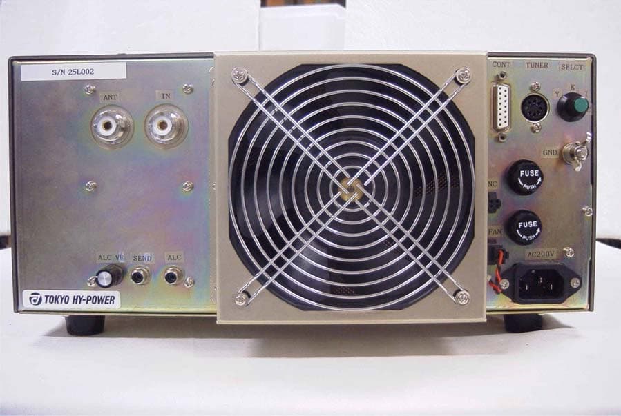
UB9HL-25KFX
Jul 02, 2007High Power Amplifier
Equipment Class
AMP - Amplifier
UB9HL-15KFX
Jun 18, 2006LINEAR AMP
Equipment Class
AMP - Amplifier