UCFURC350REMOTE CONTROL TRANSMITTER
Contec, LLC.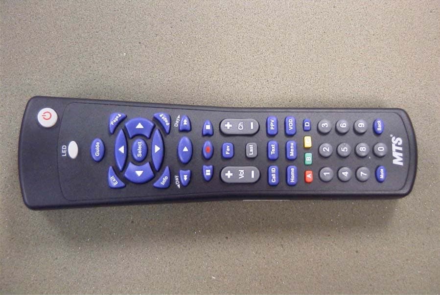
Click to zoom
Application Details
- Equipment Class
- DSC - Part 15 Security/Remote Control Transmitter
- Date of Grant
- Aug 22, 2006
- Application Purpose
- Original Equipment
- Date of Application
- Aug 22, 2006
- Equipment Note
- REMOTE CONTROL TRANSMITTER
- Frequency Range
- 433.93000000 - 433.93000000
- Company
- Contec, LLC.
- Country
- United States
Documents & Files
Document Text
Text extracted from the exhibit documents filed with the FCC. Open a document above to read the original.
Users Manual
Model SRC-350 Universal Remote Control Programming and Operating Instructions (Part # 9-542-901) To have a clearer idea of the features and capabilities of your remote control, take a moment to read these instructions. Save for future reference. © 2006 Contec Holdings, LLC, Rev. 08/06 1. Introduction Your SRC-350 remote control is simple to program, easy to use, and can operate two (2) devices, which include: • Residential Gateways (RG) • Televisions The SRC-350 remote control allows access to the features available in your Residential Gateway by using an IR (infrared) and UHF (ultra high frequency) signal, depending on how it is programmed. When the SRC-350 is set to operat e in IR mode, you must point it directly at your Residential Gateway in order to operate it. When the SRC-350 is set to operate in UHF mode, it can operate your Residential Gateway from anywhere in your home. Before you can use your SRC-350, it must be programmed (set-up) to op erate your Residential Gateway and TV. Programming your remote control is simple following the steps outlined in this manual. 2. Before Getting Started Some of the special features and buttons on your SRC-350 remote control are as follows: Point and Press® Programming Lets you program your TV without codes. For more information, see Sections 7 and 9. Memory Guard® Eliminates reprogramming after battery changes. Time Out If the same button is pressed and held for 30- seconds, your remote control will turn itself off automatically. This extends the battery life should the remote become lodged under or between heavy objects, for example sofa cushions. 3. Installing / Replacing Batteries Install two (2) new “AA” batteries as indicated by the diagram in the battery compartment. When the batteries become low and need to be replaced, the [LED] button will not illuminate normally or at all during use. When this happens, replace the existing batteries with two (2) new “AA” batteries to restore normal operation to the remote control. 4. Setting the Remote Control Operating Mode The SRC-350 remote control operates older as well as newer Residential Gateway models. To allow for this, the remote can be set to operate in either SRC-200 Compatibility Mode (to operate like the older remote control) or SRC-350 Native Mode. The default Operating Mode is SRC-200 Compatibility Mode. Programming the Remote Control Operating Mode using your SRC-350 keypad: 1. In this order, press and hold the [SELECT] button, then the [MUTE] bu tton. Hold both buttons down together until the [LED] button illuminates. Release both buttons as soon as the [LED] button illuminates. 2. Press and release the [D] key. The [LED] button temporarily turns off. Re leasing the key causes the [LED] button to light up again. You can now set the correct Operating Mode. 3. Press [0] to select SRC-200 Compatibility Mode or [1] to select SRC-350 Native Mode. The [LED] button will blink three-times and go out. The new Operating Mode is stored in the device. Important! Changing the Operating Mode from [0] to [1] will reset the Gateway ID within the SRC-350 back to [000]. Once changes have been made, the remote control resumes normal operation. If the value entered was not valid (a keypress other than [0] or [1]) the [LED] button indicates the error by turning off immediately, and the remote returns to normal operation. All values in the device remain unchanged. LED Playback of the Remote Control Operating Mode: 1. In this order, press and hold the [SELECT] button, then the [MUTE] bu tton. Hold both buttons down together until the [LED] button illuminates. Release both buttons as soon as the [LED] button illuminates. 2. Press [INFO], then [D]. The [LED] button will “blink back” the Remote Control Operating Mode. Please note that for the numeric [0], the [LED] button will blink in fast-sequence. 5. Setting The Gateway ID The Gateway ID allows your remote to talk to your Residential Gateway. The Gateway ID that you program into the remote must also be programmed into your Residential Gateway. The Gateway ID programming mode allows you to set the Gateway ID in both. Refer to your Residential Gateway User Guide for instructions on determining the Gateway ID in your Residential Gateway. NOTE: The SRC-350 Remote Control must be pointed at the Residential Gateway to program the Gateway ID in the Residential Gateway. All Remote Controls must be programmed with the same Gateway ID in order to communicate with the Gateway. Programming the Gateway ID using your SRC-350 keypad: 1. In this order, press and hold the [SELECT] button, then the [MUTE] bu tton. Hold both buttons down together until the [LED] button illuminates. Release both buttons as soon as the [LED] button illuminates. 2. Press and release the [B] key. The [LED] button temporarily turns off. Re leasing the key causes the [LED] button to light up again. You can now set the correct Gateway ID. 3. Enter the three-digit code assigned to your RG. The valid range is 004 - 999 for SRC-350s set to SRC-350 Native Mode. For SRC-350s set to SRC-200 Compatibility Mode, the valid range is 004 - 255. Enter a three-digit number, even if it contains leading zeroes. Examples of valid values are: 009, 012, 354, or 988. If you entered the Gateway ID correctly, the [LED] button will blink three-times and go out. If the value was not entered successfully, the [LED] button will go off and the remote control will return to normal operation. Repeat the steps above to try again. LED Playback of the Remote Control Gateway ID: 1. In this order, press and hold the [SELECT] button, then the [MUTE] bu tton. Hold both buttons down together until the [LED] button illuminates. Release both buttons as soon as the [LED] button illuminates. 2. Press [INFO], then [B]. The [LED] button will “blink back” the Remote Control Gateway ID. Please note that for the numeric [0], the [LED] button will blink in fast-sequence. 6. Setting The Remote Control ID The Remote Control ID allows you to con…
Text truncated - open the document above for the full version.
Block Diagram
IR transmitter MCU KeyPad 4Mhz clk EEPROM RF transmitter Main PowerBattery Voltage (1.8V ~ 3.2 V) Power on reset Device data Key data Data Save Data Read Carrier generator LED Display 433.93Mhz Rotate or single display Functional Block Diagram 36~56khz
External Photos
CONTECT HOLDINGS, LLC. FCC ID: UCFURC350 EXTERNAL PHOTOS
Internal Photos
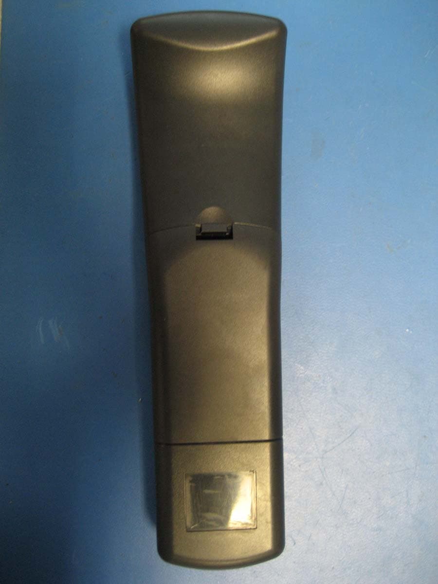
CONTECT HOLDINGS, LLC. FCC ID: UCFURC350 INTERNAL PHOTOS
Operational Description
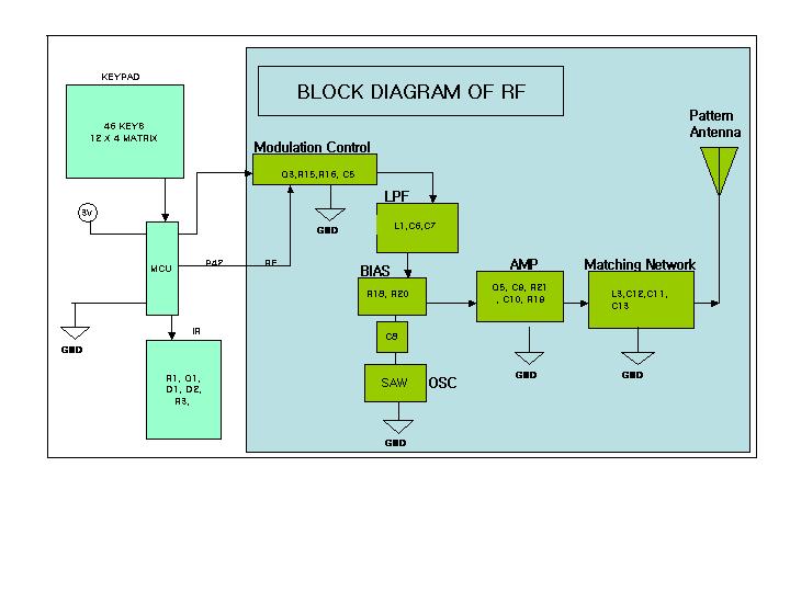
1) The SRC-350 remote is intended for use with the a set top receiver box. The operation of the remote is as follows: The SRC-350 will transmit infrared and radio frequency signals to the set top box during the following conditions: 1) Remote ID programmed in the remote is 0: Transmission is infrared only 2) Remote ID programmed in the remote is 1, 2, 3: Transmission is RF only 3) Remote TV functions are transmitted in Infrared only. The RF transmission is a low-power ASK transmitter designation for UHF band (Amplitude Shift Key). RF method of this remote uses AM. Please see picture #1. This remote use pattern antenna on the pcb itself (no external antenna). This remote is not a Spread Spectrum device and therefore there is no relation with Bit rate, Chipping Rate, Data rate and Spreading rate. Description of RF block diagram: 1) In stand-by state, P42 (RF line) is High (Logic “1”). In case of a button pressed, Q3 is turned on if P42 =0V (Logic= “0”). So, 3V power is supplied to the resonator SAW R670 (433.92 MHz) and Amp Q5 by R18, R20 through Low Pass Filter (L1, C6 and C7). Therefore Q5 can be biased by R18 and R20, to create a wireless pulse in the range of UHF. The UHF signal is amplified by Q5, C9, R21, and C10 radiating the signal to the antenna through the matching network (L3, C12, C11 and C13) which includes the pattern antenna. 2) In case when P42 is = 1V (Logic= “1”), Q3 is turned off. This case does not generate any RF signal. 1) Transmit Data Format 2) Interval of Frame At the above figures 1. BIT Rate: Max.500 bps (bit per second) 2. Data length of one frame: 12bit (3Byte) 3. Transmitting time of one frame data: 34mS~56mS
Schematics
U2 A0 1 A1 2 A2 3 GND 4 SDA 5 SCL 6 WP 7 VCC 8 C1 0.1uF Place caps close to TMP86CM47 P05 R14 820 Ohmns R72K ROW10 ROW9ROW8ROW6 VA1 ROW7ROW5 Bat_Detect ROW4 ROW11 R128.2K VCC R138.2K COL1COL3COL2COL0 R4100. Ohmns D3LED X1 4.0 Mhz X I N 1 G ND 2 X O U T 3 ROW1ROW2ROW0 VAREF ROW3 D4 1SS355 D81SS355 R18.2K IS24C08A-2G VCC VCCGND GND P42 Remove R17 and Q4 signal isinverted in software to trigger thePNP transistor Q3 Rev 02 Remove R17 and Q4 signal isinverted in software to trigger thePNP transistor Q3 Change Component Values for C7, C10, C9, R18 Rev 04 C10 = 10pfC7 = 470pfR18 = 3.3K OhmnsC9 = 12pf SCHEMATICS REV REASON FOR CHANGE L318nH CHANGE HISTORY L11.2uH C839pf C61000pfC51000pfC7470pf C1112pf C1010pf C1212pf C130.5pf C912pf R206.8kR183.3K R16510 R1510k Q5STC918SF (SOT-23)Q32SA1037K P42 VCC R2127 SAW R670433.92MHz 1 2 3 Tit leSize Document Number Rev Date: Sheet of 04 C 22 Monday , June 12, 2006 CONTEC CORPORATION Designer = Herbert L. Santeliz MAIN BOARD W_RF [ SRC 350 MODEL] TRACE Length= 16.2mm , Width = 1.2mm R19 31 ANTENA VCC DOUBLE SIDED BOARD (RF UHFCIRCUITRY) WILL BE PLACED ONTHE BOTTOM SIDE OF THE BOARDNOTES C2 0.047uF Q2 2N3904 R510MR2560K D5 1SS355 D6 1SS355 D7 1SS355 VCC IR VCC VCC C3 100uF Q1MMBTA64 D2TSAL5100 D1TSAL7600R3 1.5 Ohmns WAKE_UP R68.2K Bat_Detect P04 LED R88.2K R98.2k R10 8.2k R118.2k P04 WAKE_UP P05 U1TMP86CM47U VSS 1 XI N 2 XO U T 3 T ES T 4 V DD 5 P21 (XTIN) 6 P22 (XTOUT) 7 RESET 8 P20(STOP/INT5) 9 (INT0) P00 10 (TC4/PDO4/PPG4/PWM4)P01 11 (RXD) P02 12 (TXD) P03 13 (SO) P04 14 (SI) P05 15 (SCK) P06 16 (INT4) P07 17 P17 18 P16 19 P15 (INT3) 20 P14 (PPG) 21 P13 (DVO) 22 P12 (INT2/TC1) 23 P11 (INT1) 24 P10 (PWM3/TC3/PDO3) 25 (AIN0) P30 26 (AIN1) P31 27 (AIN2) P32 28 (AIN3) P33 29 (AIN4/STOP2) P34 30 (AIN5/STOP3) P35 31 (AIN6/STOP4) P36 32 (AIN7/STOP5) P37 33 VAREF 34 AV DD 35 AVSS 36 P40 37 P41 38 P42 39 P43 40 P44 41 P45 42 P46 43 P47 44 C4 0.1uF Tit leSize Document Number Rev Date: Sheet of 04 B 12 Tuesday , May 23, 2006 CONTEC CORPORATION Designer = Herbert L. Santeliz WIRELINE KEYPAD [ MODEL SRC-350 ] [ PAUSE ]1 [ FAV ]1 [ PAGE DWN ]1[ STOP ]1 [ REW ]1 [ INFO ]1 [ 5 ]1 [ 4 ]1 [ 3 ]1 [ 2 ]1 [ PAGE UP ]1 [ 1 ]1 [ 0 ]1 ROW0 [ B ]1 [ A ]1 [ FF ]1 [ DAY < ] [ DAY > ] [ 7 ]1 [ REC ]1 [ > ]1 [ LED ]1 [ 8 ]1 [ 6 ]1 [ C ]1 [ POWER ]1 [ 9 ]1 [ MENU ]1 [ CALL ID ]1 [ MUTE ]1 [ LED ]2 [ HOME ]1 [ EXIT ]1 COL0COL1 COL3COL2 ROW1 ROW2 ROW4 ROW3 ROW6 ROW5 ROW7 ROW9 ROW8 ROW11 ROW10 [ D ]1 [ < ]1[ < ]2 [ PLAY ]1 [ VOD]1 [ PPV ]1 [ GUIDE ]1 [ LAST ]1 [ SELECT ]1 [ ^ ]2[ ^ ]1[ V ]2[ V ]1 [ VOL- ]1[ VOL+ ]1 [ TEXT ]1 [ BACK ]1 [ CH+ ]1 [ CH- ]1
Test Report
TIMCO ENGINEERING INC. 849 NW State Road 45 Newberry, Florida 32669 http://www.timcoengr.com 888.472.2424 F 352.472.2030 email: [email protected] APPLICANT: CONTEC HOLDINGS, LLC FCC ID: UCFURC350 REPORT #: C\CONTEC\1289UT6\1289UT6TestReport.doc COVER SHEET Test Report Product Name: REMOTE CONTROL TRANSMITTER FCC ID: UCFURC350 Applicant: CONTEC HOLDINGS, LLC 1011 & 1023 STATE STREET SCHENECTADY NY 12307 USA Date Receipt: 6/19/2006 Date Tested: 7/18/2006 TIMCO ENGINEERING INC. 849 NW State Road 45 Newberry, Florida 32669 http://www.timcoengr.com 888.472.2424 F 352.472.2030 email: [email protected] APPLICANT: CONTEC HOLDINGS, LLC FCC ID: UCFURC350 REPORT #: C\CONTEC\1289UT6\1289UT6TestReport.doc TABLE OF CONTENTS TABLE OF CONTENTS APPLICANT: CONTEC HOLDINGS, LLC FCC ID: UCFURC350 TEST REPORT CONTAINING: PAGE 1.............TEST EQUIPMENT LIST PAGE 2.............TEST PROCEDURE PAGE 3-4...........RADIATION INTERFERENCE TEST DATA PAGE 5.............CALCULATION OF DUTY CYCLE PAGE 6-8...........DUTY CYCLE PLOTS PAGE 9.............OCCUPIED BANDWIDTH EXHIBIT INCLUDING: BLOCK DIAGRAM SCHEMATIC INSTRUCTION MANUAL LABEL SAMPLE LABEL LOCATION EXTERNAL PHOTOGRAPHS INTERNAL PHOTOGRAPHS OPERATIONAL DESCRIPTION TEST SET UP PHOTOGRAPH TIMCO ENGINEERING INC. 849 NW State Road 45 Newberry, Florida 32669 http://www.timcoengr.com 888.472.2424 F 352.472.2030 email: [email protected] APPLICANT: CONTEC HOLDINGS, LLC FCC ID: UCFURC350 REPORT #: C\CONTEC\1289UT6\1289UT6TestReport.doc Page 1 of 9 EMC Equipment List Device Manufacturer Model Serial Number Cal/Char Date Due Date 3-Meter OATS TEI N/A N/A Listed 1/11/06 1/10/09 3/10-Meter OATS TEI N/A N/A Listed 3/27/04 3/26/07 Analyzer Tan Tower Spectrum Analyzer HP 8566B Opt 462 3138A07786 3144A20661 CAL 12/7/05 12/7/07 Analyzer Tan Tower RF Preselector HP 85685A 3221A01400 CAL 12/7/05 12/7/07 Analyzer Tan Tower Quasi- Peak Adapter HP 85650A 3303A01690 CAL 12/8/05 12/8/07 Analyzer Tan Tower Preamplifier HP 8449B-H02 3008A00372 CAL 12/8/05 12/8/07 Analyzer Blue Tower Spectrum Analyzer HP 8568B 2928A04729 2848A18049 CAL 4/13/05 4/13/07 Analyzer Blue Tower RF Preselector HP 85685A 2926A00983 CAL 9/5/05 9/5/07 Analyzer Blue Tower Quasi- Peak Adapter HP 85650A 2811A01279 CAL 4/13/05 4/13/07 Analyzer Silver Tower Spectrum Analyzer HP 8566B Opt 462 3552A22064 3638A08608 CAL 12/8/04 12/8/06 Analyzer Silver Tower RF Preselector HP 85685A 2620A00294 CAL 4/27/04 12/8/06 Analyzer Silver Tower Quasi- Peak Adapter HP 85650A 3303A01844 CAL 12/8/04 12/8/06 Analyzer Open- Frame Tower Preamplifier HP 8449B 3008A01075 CAL 8/8/05 8/8/07 Antenna: Biconnical Electro-Metrics BIA-25 1171 CAL 4/29/05 4/29/07 Antenna: Biconnical Eaton 94455-1 1096 CAL 8/17/04 8/17/06 Antenna: Biconnical Eaton 94455-1 1057 CAL 12/12/05 12/12/07 Antenna: Log- Periodic Electro-Metrics LPA-25 1122 CAL 8/26/04 8/26/06 TIMCO ENGINEERING INC. 849 NW State Road 45 Newberry, Florida 32669 http://www.timcoengr.com 888.472.2424 F 352.472.2030 email: [email protected] APPLICANT: CONTEC HOLDINGS, LLC FCC ID: UCFURC350 REPORT #: C\CONTEC\1289UT6\1289UT6TestReport.doc Page 2 of 9 TEST PROCEDURE GENERAL: This report shall NOT be reproduced except in full without the written approval of TIMCO ENGINEERING, INC. RADIATION INTERFERENCE: The test procedure used was ANSI STANDARD C63.4-2003 using a HEWLETT PACKARD spectrum analyzer with a preselector. The bandwidth of the spectrum analyzer was 100 kHz with an appropriate sweep speed. The analyzer was calibrated in dB above a microvolt at the output of the antenna. The resolution bandwidth was 100 kHz and the video bandwidth was 300 kHz. The ambient temperature of the UUT was 98.3ºF with a humidity of 40%. FORMULA OF CONVERSION FACTORS: The Field Strength at 3m was established by adding the meter reading of the spectrum analyzer (which is set to read in units of dBuV) to the antenna correction factor supplied by the antenna manufacturer. The antenna correction factors are stated in terms of dB. The gain of the Preselector was accounted for in the Spectrum Analyzer Meter Reading. Example: Freq (MHz) METER READING + ACF = FS 33 20 dBuV + 10.36 dB = 30.36 dBuV/m @ 3m ANSI STANDARD C63.4-2003 10.1.7 MEASUREMENT PROCEDURES: The UUT was placed on a table 80 cm high and with dimensions of 1m by 1.5m. The UUT was placed in the center of the table. The table used for radiated measurements is capable of continuous rotation. The spectrum was scanned from 30 MHz to 10th harmonic of the fundamental. Peak readings were taken in three (3) orthogonal planes and the highest readings were converted to average readings based on the duration of "ON" time. When an emission was found, the table was rotated to produce the maximum signal strength. At this point, the antenna was raised and lowered from 1m to 4m. The antenna was placed in both the horizontal and vertical planes. Measurements were made by TIMCO ENGINEERING INC. at the registered open field test site located at 849 N.W. State Road 45, Newberry, Fl 32669. TIMCO ENGINEERING INC. 849 NW State Road 45 Newberry, Florida 32669 http://www.timcoengr.com 888.472.2424 F 352.472.2030 email: [email protected] APPLICANT: CONTEC HOLDINGS, LLC FCC ID: UCFURC350 REPORT #: C\CONTEC\1289UT6\1289UT6TestReport.doc Page 3 of 9 APPLICANT: CONTEC HOLDINGS, LLC FCC ID: UCFURC350 NAME OF TEST: RADIATION INTERFERENCE RULES PART NO.: 15.231 REQUIREMENTS: Fundamental Field Strength Field Strength of Frequency of Fundamental Harmonics and Spurious MHz dBuV Emissions (dBuV/m @ 3m) 40.66 to 40.70 67.04 47.04 70 to 130 61.94 41.94 130 to 174 61.94 to 71.48 41.94 to 51.48 174 to 260 71.48 51.48 260 to 470 71.48 to 81.94 51.48 to 61.94 470 and above 81.94 61.94 THE LIMIT FOR AVERAGE FIELD STRENGTH dBuV/m FOR THE FUNDAMENTAL FREQUENCY = 80.82 dBuV/m. NO FUNDAMENTAL IS ALLOWED IN THE RESTRICTED BANDS. THE LIMIT FOR AVERAGE FIELD STRENGTH dBuV/m FOR THE HARMONICS AND SPURIOUS FREQUENCIES = 60.82 dBuV/m. SPURIOUS IN THE RESTRICTED BANDS MUST BE LESS THAN 54 dBuV/m OR 15.209. TEST D…
Text truncated - open the document above for the full version.
Contact Information
Applicant
Herbert Santeliz(R&D Project Leader)
Test Firm
Timco Engineering, Inc.Sid Sanders
Technical Specifications
| # | Rule Parts | Frequency Range | Power Output |
|---|---|---|---|
| 1 | 15.231 | 433.93 MHz - 433.93 MHz | - |
Other Applications from Contec, LLC.
UCFURC350A
Mar 06, 2007REMOTE CONTROL
Equipment Class
DSC - Part 15 Security/Remote Control Transmitter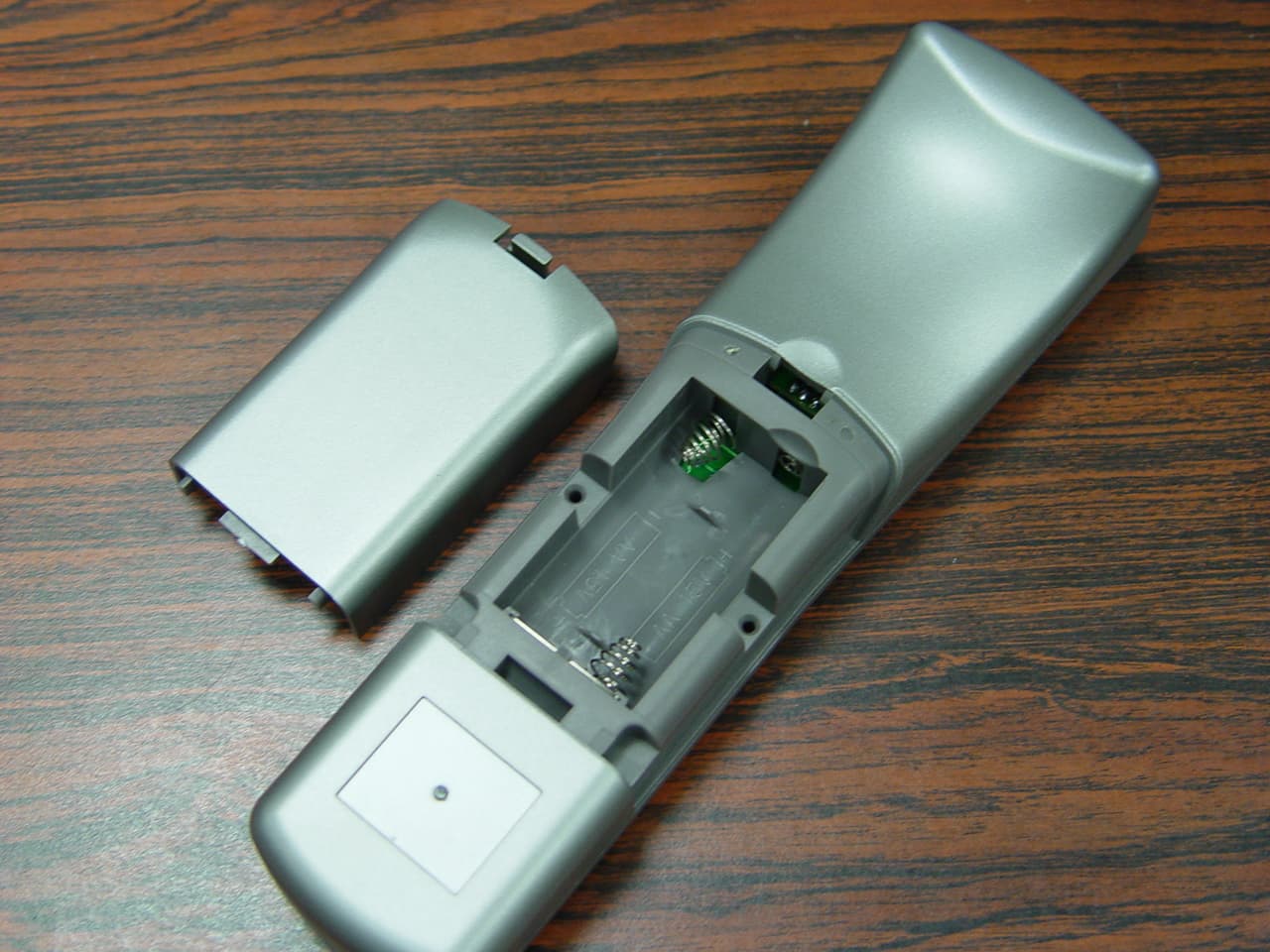
UCFURC550
Jul 04, 2006UNIVERSAL REMOTE CONTROL
Equipment Class
DSC - Part 15 Security/Remote Control Transmitter