UCS940663Electronic identification reader device for dairy cows
DeLaval International AB
Click to zoom
Application Details
- Equipment Class
- DCD - Part 15 Low Power Transmitter Below 1705 kHz
- Date of Grant
- Jan 03, 2016
- Application Purpose
- Original Equipment
- Date of Application
- Jan 03, 2016
- Equipment Note
- Electronic identification reader device for dairy cows
- Frequency Range
- 0.13420000 - 0.13420000
- Company
- DeLaval International AB
- Country
- Sweden
Documents & Files
Document Text
Text extracted from the exhibit documents filed with the FCC. Open a document above to read the original.
Users Manual
Preliminary 941322_VMS Instruction Book 2006.pdf2009-09-07 No.NameRangeDefaultDescription/optionsNo.NameRangeDefaultDescription/options 0 = no acidic cleaning0 = no acidic cleaning 1 = one alkaline, one acidic cleaning1 = one alkaline, one acidic cleaning 2 = two alkaline, one acidic cleaning2 = two alkaline, one acidic cleaning 3 = etc.3 = etc. Maintenance an calibration The following points are important to sustain correct dosing of etergents. Note that these two tasks should be performed by an authorised DeLaval service engineer. •The tubes in the peristaltic pumps should be replaced at least two times a year. •The dosing volume (P6-P8) of the detergent pumps should be checked every third month. The dosing capacity (P32-P34) may need to be adjusted. Starting cleaning or rinsing from the touch screen Note: Any ongoing backflush process must first be finished before cleaning or rinsing can be started. 1. Ensure that the milking station is in manual mode. 2. Remove any cow that might be in the milking station. After treatment window Note: Both gates should be closed to prevent a cow from entering before the system cleaning has been started. Closing and opening gates is done in the Stall control window. 3. Press the tab After Treatment on the touch screen to display the After treatment window. 4. In the After treatment window, press the Cleaning and Rinsing button. This will open the Cleaning and rinsing window. DeLaval ID reader walk by IRW Instruction Book © DeLaval 2015.87086801 2015-10-13, Version 5Original instruction Preliminary 941322_VMS Instruction Book 2006.pdf2009-09-07 No.NameRangeDefaultDescription/optionsNo.NameRangeDefaultDescription/options 0 = no acidic cleaning0 = no acidic cleaning 1 = one alkaline, one acidic cleaning1 = one alkaline, one acidic cleaning 2 = two alkaline, one acidic cleaning2 = two alkaline, one acidic cleaning 3 = etc.3 = etc. Maintenance an calibration The following points are important to sustain correct dosing of etergents. Note that these two tasks should be performed by an authorised DeLaval service engineer. •The tubes in the peristaltic pumps should be replaced at least two times a year. •The dosing volume (P6-P8) of the detergent pumps should be checked every third month. The dosing capacity (P32-P34) may need to be adjusted. Starting cleaning or rinsing from the touch screen Note: Any ongoing backflush process must first be finished before cleaning or rinsing can be started. 1. Ensure that the milking station is in manual mode. 2. Remove any cow that might be in the milking station. After treatment window Note: Both gates should be closed to prevent a cow from entering before the system cleaning has been started. Closing and opening gates is done in the Stall control window. 3. Press the tab After Treatment on the touch screen to display the After treatment window. 4. In the After treatment window, press the Cleaning and Rinsing button. This will open the Cleaning and rinsing window. Preliminary 941322_VMS Instruction Book 2006.pdf2009-09-07 No.NameRangeDefaultDescription/optionsNo.NameRangeDefaultDescription/options 0 = no acidic cleaning0 = no acidic cleaning 1 = one alkaline, one acidic cleaning1 = one alkaline, one acidic cleaning 2 = two alkaline, one acidic cleaning2 = two alkaline, one acidic cleaning 3 = etc.3 = etc. Maintenance an calibration The following points are important to sustain correct dosing of etergents. Note that these two tasks should be performed by an authorised DeLaval service engineer. •The tubes in the peristaltic pumps should be replaced at least two times a year. •The dosing volume (P6-P8) of the detergent pumps should be checked every third month. The dosing capacity (P32-P34) may need to be adjusted. Starting cleaning or rinsing from the touch screen Note: Any ongoing backflush process must first be finished before cleaning or rinsing can be started. 1. Ensure that the milking station is in manual mode. 2. Remove any cow that might be in the milking station. After treatment window Note: Both gates should be closed to prevent a cow from entering before the system cleaning has been started. Closing and opening gates is done in the Stall control window. 3. Press the tab After Treatment on the touch screen to display the After treatment window. 4. In the After treatment window, press the Cleaning and Rinsing button. This will open the Cleaning and rinsing window. EC Declaration of Conformity - DeLaval ID reader walk by IRW.....................................................5 Safety precautions..............................................................................................................................7 nDeLaval ID reader walk by IRW 1 Foreword...........................................................................................................................7 2 Disclaimer.........................................................................................................................7 3 Safety regulations.............................................................................................................7 4 FCC statement..................................................................................................................8 5 IC Compliance statement..................................................................................................8 6 Safety labels on the equipment.........................................................................................9 7 Type plate.........................................................................................................................9 8 Warranty..........................................................................................................................10 General description...........................................................................................................................11 nDeLaval ID reader walk by IRW 1 Introduction..................................................…
Text truncated - open the document above for the full version.
Users Manual
Rideau d'idendification IRW DeLaval Guide de l’utilisateur © DeLaval 2015.87086813 2015-11-02, Version 5Guide de l'utilisateur original Déclaration de conformité CE - Rideau d'idendification IRW DeLaval...........................................5 Consignes de sécurité........................................................................................................................7 nRideau d'idendification IRW DeLaval 1 Avant-propos.....................................................................................................................7 2 Avis de non-responsabilité................................................................................................7 3 Règlements de sécurité....................................................................................................7 4 Déclaration de conformité FCC.........................................................................................8 5 Déclaration de conformité IC.............................................................................................9 6 Étiquettes de sécurité sur l'équipement..........................................................................10 7 Plaque signalétique.........................................................................................................10 8 Garantie..........................................................................................................................11 Description générale.........................................................................................................................12 nRideau d'idendification IRW DeLaval 1 Introduction.....................................................................................................................12 Entretien effectué par l'opérateur....................................................................................................14 nRideau d'idendification IRW DeLaval 1 Tâches d'entretien...........................................................................................................14 Recherche de pannes.......................................................................................................................16 nRideau d'idendification IRW DeLaval 1 Généralités......................................................................................................................16 Élimination.........................................................................................................................................17 nRideau d'idendification IRW DeLaval 1 Informations relatives à l'élimination et au recyclage ....................................................17 1.1 Élimination des matériaux d'emballage..........................................................17 1.2 Élimination des équipements électriques et électroniques avec ou sans batterie..............................................................................................................17 Rideau d'idendification IRW DeLaval Table des matières © DeLaval 2015. 2015-11-02, Version 53 (20)87086813 Rideau d'idendification IRW DeLaval Table des matières © DeLaval 2015. 2015-11-02, Version 54 (20)87086813 Déclaration de conformité CE Nom du produit :Rideau d'idendification IRW DeLaval Type :IRW-FDX réf. 94066382 Rapport No.80009947 version 1 Le produit est conforme aux exigences des directives suivantes : Directive 1999/5/CE concernant les équipements hertziens et les équipements termi- naux de télécommunications Directive relative à la limitation de l’utilisation de certaines substances dangereuses - 2011/65/UE Normes harmonisées qui ont été utilisées : ETSI EN 300 330-1 V1.7.1 (2010-02) ETSI EN 302 330-2 V1.5.1 (2010-02) EN 301 489-01 (V1.9.2) EN 301 489-03 (V1.6.1) EN 61000-6-4 (2007) + A1 (2011) EN 61000-6-2 (2005) Autres normes et spécifications techniques qui ont été utilisées : Conforme à la directive RoHS, 2011/65/EU en matière de contrôle de la conception et de l'achat Tumba 2015-10-21Signature : Nom :Jonas Hällman Fonction :Executive Vice President Département :Business Area Milking Systems Contact :Product Manager P.O. Box 39 SE 147 21 TUMBA Sweden © DeLaval 2015. 2015-11-02, Version 55 (20)87086813 Nom et adresse du fabricant : DeLaval International AB P.O. Box 39 SE 147 21 TUMBA Sweden © DeLaval 2015. 2015-11-02, Version 56 (20)87086813 Consignes de sécurité Rideau d'idendification IRW DeLaval 1 Avant-propos Il est de votre responsabilité de vous assurer que les personnes en charge de l'utilisation ou du fonctionnent de cet équipement suivent toutes les consignes de sécurité et les instructions de fonctionnement pour cet équipement. Vous ne devez en aucun cas utiliser cet appareil s'il pré- sente des défauts. L'utilisation de ce matériel est réservée aux personnes averties et formées. 2 Avis de non-responsabilité Les informations, les instructions et les pièces indiquées dans ce manuel sont applicables à la date de parution de ce manuel. DeLaval se réserve le droit d'effectuer toute modification nécessaire à l'amélioration de ses matériels sans préavis. 3 Règlements de sécurité Avertissement ! L'équipement est lourd et pourrait provoquer de graves blessures par écrasement en cas de chute. Obligatoire ! Débranchez toujours l'équipement avant de déposer les carters, les capots et les autres dispositifs de sécurité. Rideau d'idendification IRW DeLaval Consignes de sécurité © DeLaval 2015. 2015-11-02, Version 57 (20)87086813 4 Déclaration de conformité FCC Remarque ! Toutes transformations ou modifi- cations apportées à l'équipement non expressé- ment autorisées par l'entité responsable de la conformité peuvent faire perdre à l'utilisateur son droit de faire fonctionner cet équipement. Cet équipement a été testé et déclaré conforme aux limites pour appareils numériques de classe B, conformément à la section 15 des règlements de la FCC. Ces limites visent à garantir une pro- tection raisonnable contre les interférences nui- sibles dans une installation résiden…
Text truncated - open the document above for the full version.
Users Manual
Planning DeLaval ID reader walk by IRW 1 General General points to consider before ordering and installing the IRW: nDeLaval ID reader walk by IRW is used to identify cows with B-transponders or ISO transponders. nThe IRW will be set to read either B or ISO transponders, meaning that the entire herd must have the same type of transponder. nISO transponders must be attached to the same ear for the entire herd. If new cows are introduced, always check that their trans- ponders are placed on the same ear as the rest of the herd. nThe IRW is mostly installed on the framework of the parlour entrance or a sort gate. An alley must always be provided so the cows pass the IRW one by one. An arch above the IRW is recommended. nIf the IRW should read ISO transponders, it must be placed on the left side of the parlour entrance or sort gate for herds having the transponders attached to the left ear, and vice versa. 2 Article numbers Article number Description 94066381DeLaval ID reader walk by IRW (does not include photocell and bracket) 94066334Photocell and bracket (only used in HB30/50) 233226 Fig. 1 DeLaval ID reader walk by IRW Planning © DeLaval 2015. 2015-09-11, Version 51 (27) 3 Technical data A F B E C D 232467 Fig. 2 A (height)1.64 m B (width)1.06 m C (depth)0.2 m D0.8 m E 1 (pipe, Ø60.3 mm)920-945 mm Option E 2 (pipe, Ø48.3 mm) 929 mm F1.25 m Weight70 kg Input voltage12 VAC +20%, -10% Power30 VA DeLaval ID reader walk by IRW Planning © DeLaval 2015. 2015-09-11, Version 52 (27) Current consumption IRW1.5 A rms IRW including photocell and control valve 2.4 A rms (ALPRO ID sync) Portal reader (Blue curtain), for comparison ID portal0.6 A rms ID portal including photocell and control valve1.3 A rms Note! The IRW has a bigger current consumption than the old portal reader. Note! IRW must has its own power supply, can not share a transformer with some of the MPC's. DeLaval ID reader walk by IRW Planning © DeLaval 2015. 2015-09-11, Version 53 (27) 4 Reading range The reading range is the area in which the IRW can read a transponder. An electromagnetic field is used to read the transponders. To get a good reading range, a "safety area" must be used around the IRW. Inside this area it is not allowed to have metal-reinforced building struc- tures or other metal equipment that might short circuit the electromagnetic field of the IRW. Recommended dimensions of this safety area: nSingle cow walkway width: 800 mm. nSingle cow walkway length from the IRW: Minimum 1500 mm. nSafety distance from the IRW front: Minimum 1500 mm. nSafety distance from the IRW back: Minimum 200 mm. 217250 Fig. 3: Electromagnetic field from the IRW. 800 1500 200 800 1500 233227 Fig. 4: Safety area around the IRW. DeLaval ID reader walk by IRW Planning © DeLaval 2015. 2015-09-11, Version 54 (27) 5 Placing the IRW at a parlour or rotary entrance Note! It is important to plan the entrance cor- rectly so that only one cow at a time is picked up by the IRW. nThe IRW should be located directly in front of, or as close as possible to, the parlour entrance gate. nSeparate the return cow traffic from the single cow walkway close to the IRW so that no unwanted transponders are read by the IRW. – A regular steel fence is recommended. This will interfere as little as possible with the electromagnetic field of the IRW. – A solid wall or steel wall is less favoura- ble. nNever place a fence directly in front of the IRW. 6 Placing the IRW at a sort gate DeLaval sort gates are designed for mounting an IRW. 233230 Fig. 5: Parlour entrance with an IRW. 233228 Fig. 6: DeLaval sort gate DSG3 with an IRW. DeLaval ID reader walk by IRW Planning © DeLaval 2015. 2015-09-11, Version 55 (27) Installation DeLaval ID reader walk by IRW 1 General Warning! The equipment is heavy and could cause serious crushing injury if drop- ped. Note! It is recommended to have two fitters avail- able when lifting and installing the IRW. Note! Working transponders are needed. Note! Take care when installing the IRW. Incor- rect installation will result in poor system per- formance with unacceptable levels of missed identification. Follow the tasks in this chapter in the given order. DeLaval ID reader walk by IRW Installation © DeLaval 2015. 2015-09-11, Version 56 (27) 2 Installing the IRW To install the IRW: 1.Lift the IRW into place, using the lifting eyes on the mounting brackets. 2.Place the IRW at the desired location. For more information, see chapter "Planning" for product "DeLaval ID reader walk by IRW". 233229 Fig. 7 DeLaval ID reader walk by IRW Installation © DeLaval 2015. 2015-09-11, Version 57 (27) 233231 Fig. 8: IRW mounted to a DeLaval sort gate DSG2/3. 3.Mount the IRW to the pipes, using clamps to fasten it. Recommended pipe dimension is 60.3 mm or 48 mm. DeLaval ID reader walk by IRW Installation © DeLaval 2015. 2015-09-11, Version 58 (27) 4.Place the IRW at the correct height, see Fig. 9. A 232469 Fig. 9 A:175 mm DeLaval ID reader walk by IRW Installation © DeLaval 2015. 2015-09-11, Version 59 (27) 3 Installing the photocell To install the photocell: 1.Determine which slot the photocell should be installed in. In general the photocell should be installed in the slot closest to the parlour. If the entrance gate is close to the antenna and if there is a possibility for the cows head to be outside the reading range, the photocell should be install in the first slot. Note! Only for HB30/50. 233232 Fig. 10: Photocell installation slot. DeLaval ID reader walk by IRW Installation © DeLaval 2015. 2015-09-11, Version 510 (27) 2.Remove the top-left cover of the IRW (A). 3.Remove the cover (B) at the top of the IRW and disconnect power. 4.Remove the cover from the installation slot (C). 5.Pull the photocell cables (D) through the cable channel (E), using a cable puller. 6.Fasten the photocell and the bracket to the IRW with two screws (F). 7.Connect the cables according to Ä Chapter 4.3 "Connecting the cables" on page 14. 8.Put back the top-left cover and the cover t…
Text truncated - open the document above for the full version.
External Photos
EXTERNAL PHOTOS AND ACCESSORIES Project no.: 273436 FCC ID: UCS940663 Page 1 (4) EXTERNAL PHOTOS – IRW-FDX The EUT with antenna and enclosure – front side EXTERNAL PHOTOS AND ACCESSORIES Project no.: 273436 FCC ID: UCS940663 Page 2 (4) Rear side EXTERNAL PHOTOS AND ACCESSORIES Project no.: 273436 FCC ID: UCS940663 Page 3 (4) ACCESSORIES Alpro (Control device) EXTERNAL PHOTOS AND ACCESSORIES Project no.: 273436 FCC ID: UCS940663 Page 4 (4) Transponder (Tag)
Internal Photos
INTERNAL PHOTOS Project no.: 273436 FCC ID: UCS940663 Page 1 (2) INTERNAL PHOTOS – IRW-FDX Main board of the EUT – components side INTERNAL PHOTOS Project no.: 273436 FCC ID: UCS940663 Page 2 (2) Main board of the EUT – rear side
Operational Description
Draft 0.1 1 Description IRW 1.1 Block diagram IRW 1.2 Operational Description IRW 1.2.1 Power amplifier For the energy-transmission. The energy is sent as a signal with frequency 131,3 kHz or 134.2 kHz. The frequency is set via the bus interface. 1.2.2 Autotuning Circuitry to adapt the IRW to variations in the antenna coil inductance, and the different transmitted frequencies. 1.2.3 FDX env. Demod Filter and amp Transponder signal demodulation and preamplification circuitry. FDX signals goes through an envelope demodulator, filter and amplifier. 1.2.4 HDX filter and amplification The HDX signal goes through filtering and amplification. 1.2.5 CPU signal detector The micro controller detects the transponder signal after previous signal conditioning. The CPU also controls the auto tuning to adapt for antenna variations and other variables that affect the inductance for the antenna. 1.2.6 Communication CPU, DIG I/O An administrative processor handling communication to the bus interface and controlling the digital inputs and outputs. Digital inputs and outputs used for reading sensors like photocell, and when the IRW is used for applications like pneumatic selection gates. 1.2.7 Antenna The antenna is made of litz wire formed like an eight on a plastic panel. 1.2.8 Power supply Circuitry including a bridge rectifier and step-down converter. 2 Description MRR 2.1 Block diagram MRR 2.2 Operational Description MRR 2.2.1 Power amplifier, Transmitter, Autotuning The MultiRod transmitter is automatically tuned. The auto tuning starts immediately after power startup. The transmitter starts when the signal Activation sync, X1-2, in the serial interface receive 12VDC. When the controller signal is high a pulse train is given from to the transmitters MOSFET driver. This pulse train is 131kHz or 134,2kHz every second time. The FET:s are then powering the antenna. During auto tuning a combination of capacitors are set for the two frequencies 131kHz and 134,2kHz to make the antenna and the capacitors in resonance. 2.2.2 Receiver, Serial interface During excitation the FDX signal will be received trough the antenna and the envelope detector. The demodulated signal is amplified. The received signal both for HDX B and FDX chain is decoded by the CPU and the signal is converted to Manchester code and NRZ code. The NRZ coded signal is sent first followed by the Manchester code over the serial interface. ISO transponders sent as Manchester code is a shortened number and contains only the 4 les s significant digits in the number. B-transponder sent as NRZ code is sent as a 64 bit identification code followed by 16 bit CRC. 2.2.3 Antenna The antenna is potted inside the unit and is built by copper windings on ferrite material. 2.2.4 Power supply Circuitry including internal linear regulators to provide regulated power to the electronic circuits in the other blocks.
Test Report
Report No. 3-273436 Template version: B Nemko Norway Nemko AS, Instituttveien 6, P.O. Box 96 Kjeller, 2027 Kjeller, Norway TEL +47 22 96 03 30 FAX +47 22 96 05 50 EMAIL [email protected] ENTERPRISE NUMBER NO974404532 nemko.com/no Test Report Product ID Reader Walk by Name and address of the applicant DeLaval Gustav Delavals veg 15, SE-147021 Tumba, Sweden Name and address of the manufacturer BioControl AS Gautestadveien 75, N-1890 Rakkestad,Norway Model 94066382 Rating 12Vac Trademark DeLaval Serial number / Additional information 131.072 kHz & 134.2 kHz RFID Tested according to FCC Part 15.209 Digital Transmission Systems Industry Canada RSS-210, Issue 8 Low Power Licence-Exempt Radiocommunications Devices Order number 273436 Tested in period 2014.11.21 - 2014.11.29 Issue date 2015.12.22 Name and address of the testing laboratory Instituttveien 6 Kjeller, Norway FCC No: 994405 IC OATS: 2040D-1 TEL: +47 22 96 03 30 FAX: +47 22 96 05 50 Prepared by [G.Suhanthakumar] Approved by [Frode Sveiensen] This report shall not be reproduced except in full without the written approval of Nemko. Opinions and interpretations expressed within this report are not part of the current accreditation. This report was originally distributed electronically with digital signatures. For more information contact Nemko. TEST REPORT FCC Part 15C.209 Report no.: 3-273436 FCC ID: UCS940663 Nemko Norway, Instituttveien 6, Kjeller, Norway Page 2 (25) CONTENTS 1 INFORMATION ......................................................................................................................... 3 1.1 Test Item.................................................................................................................................... 3 1.2 Test Environment ...................................................................................................................... 4 1.2.1 Normal test condition ................................................................................................... 4 1.3 Test Engineer(s) ........................................................................................................................ 4 1.4 Test Equipment ......................................................................................................................... 4 2 TEST REPORT SUMMARY ...................................................................................................... 5 2.1 General ...................................................................................................................................... 5 2.2 Test Summary ........................................................................................................................... 6 2.3 Description of modification for Modification Filing ..................................................................... 6 2.4 Comments ................................................................................................................................. 6 2.5 Family List Rational ................................................................................................................... 6 3 TEST RESULTS ........................................................................................................................ 7 3.1 Power Line Conducted Emissions ............................................................................................. 7 3.2 20 dB Bandwidth ....................................................................................................................... 9 3.3 Spurious Emissions (Radiated) ............................................................................................... 12 4 LIST OF TEST EQUIPMENT .................................................................................................. 23 5 BLOCK DIAGRAM .................................................................................................................. 24 5.1 Power Line Conducted Emission ............................................................................................. 24 5.2 Test Setup Radiated Emission ................................................................................................ 24 TEST REPORT FCC Part 15C.209 Report no.: 3-273436 FCC ID: UCS940663 Nemko Norway, Instituttveien 6, Kjeller, Norway Page 3 (25) 1 INFORMATION 1.1 Test Item Name : ID Reader Walk by FCC ID : UCS940663 IC : 6576A-940663 Model/version : 94066382 Serial number : - Hardware identity and/or version: - Software identity and/or version : - Frequency Range : 131.072 – 134.2 kHz Operating frequency : 131.072 kHz & 134.2 kHz Type of Modulation : Unmodulated CW signal Output Power: 0.00079 W (Average, Radiated) User Frequency Adjustment : None Type of Power Supply : 12Vac 60Hz (Input voltage to stepdown transformer is 120Vac/60Hz) Antenna Connector : No (integral loop antenna) Antenna Diversity Supported : No Description of Test Item The test item is a RFID reader/transmitter that transmit a field with frequency either 131.1 kHz or 134.2 kHz. The reader is a transponder reader that is a part of a system and is controlled by a controller unit called alpro. The alpro can by commanded to change between 131.1 kHz and 134.2 kHz. The transmitted signal is an unmodulated CW signal. TEST REPORT FCC Part 15C.209 Report no.: 3-273436 FCC ID: UCS940663 Nemko Norway, Instituttveien 6, Kjeller, Norway Page 4 (25) 1.2 Test Environment 1.2.1 Normal test condition Temperature: 20 - 23 °C Relative humidity: 40 - 50 % Normal test voltage: 120V AC The values are the limit registered during the test period. 1.3 Test Engineer(s) G.Suhanthakumar 1.4 Test Equipment See list of test equipment in clause 4. TEST REPORT FCC Part 15C.209 Report no.: 3-273436 FCC ID: UCS940663 Nemko Norway, Instituttveien 6, Kjeller, Norway Page 5 (25) 2 TEST REPORT SUMMARY 2.1 General All measurements are tracable to national standards. The tests were conducted for the purpose of demonstrating compliance with FCC CFR 47 Part 1…
Text truncated - open the document above for the full version.
Test Setup Photos
TEST SET-UP PHOTOS Project no.: 273436 FCC ID: UCS940663 Page 1 (2) PHOTOS OF TEST SET-UP Radiated emissions - < 30MHz, 10 meter Radiated Emissions 30 - 1000 MHz, 3 meter TEST SET-UP PHOTOS Project no.: 273436 FCC ID: UCS940663 Page 2 (2) Radiated emissions 1 – 6 GHz, 3 meter
Contact Information
Applicant
Susanne Sundstroem(Product Compliance)
Test Firm
Nemko ASFrode Sveinsen
Technical Specifications
| # | Rule Parts | Frequency Range | Power Output |
|---|---|---|---|
| 2 | 15C | 0.1342 MHz - 0.1342 MHz | - |
Other Applications from DeLaval International AB

UCS2150024802
Jan 02, 2023Farm monitoring Camera FMC- IP1.1 US
Equipment Class
DTS - Digital Transmission System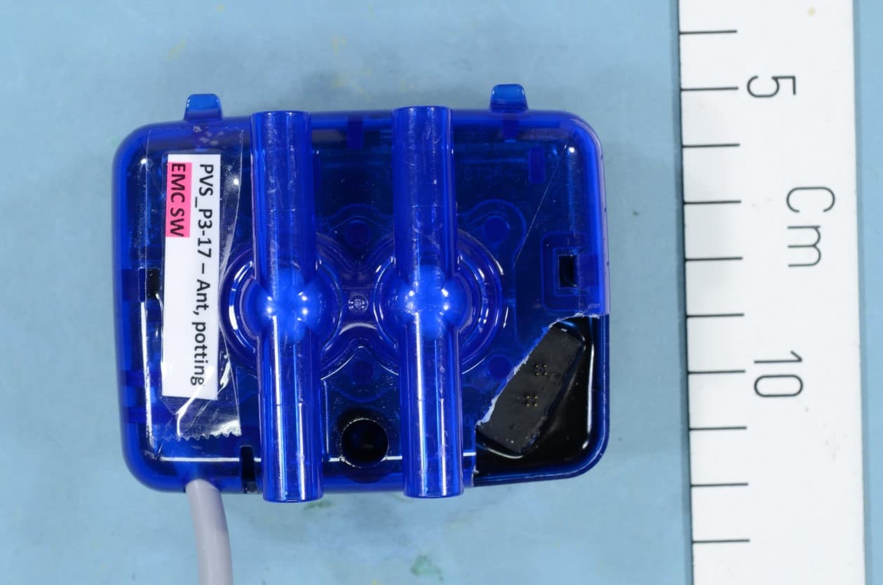
UCSPVS100
Sep 20, 2020Pulsation and u Sensor
Equipment Class
DTS - Digital Transmission System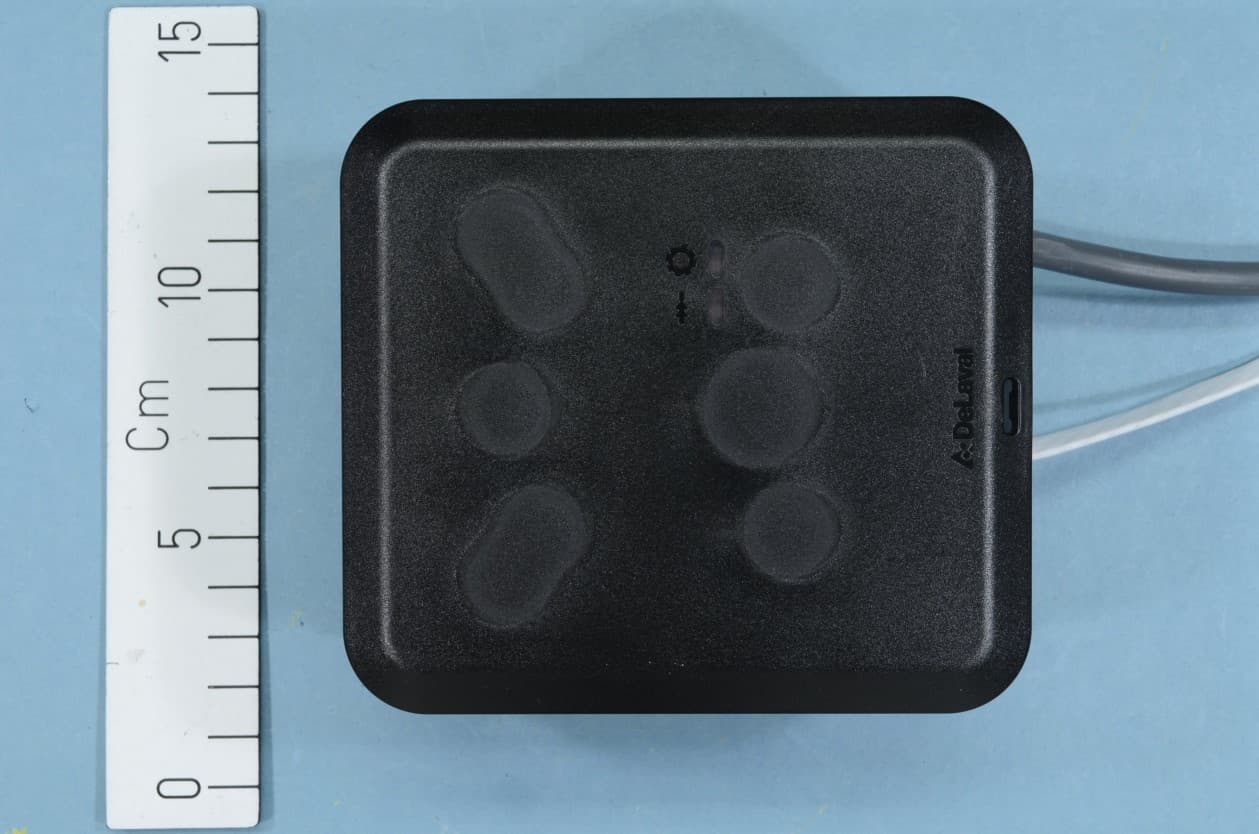
UCSCCM315
Sep 17, 2020Control and Communication Module
Equipment Class
DTS - Digital Transmission System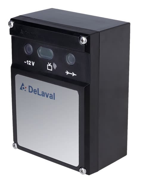
UCS86120691
Feb 23, 2015Cow activity meter system 418 MHz
Equipment Class
DSR - Part 15 Remote Control/Security Device Transceiver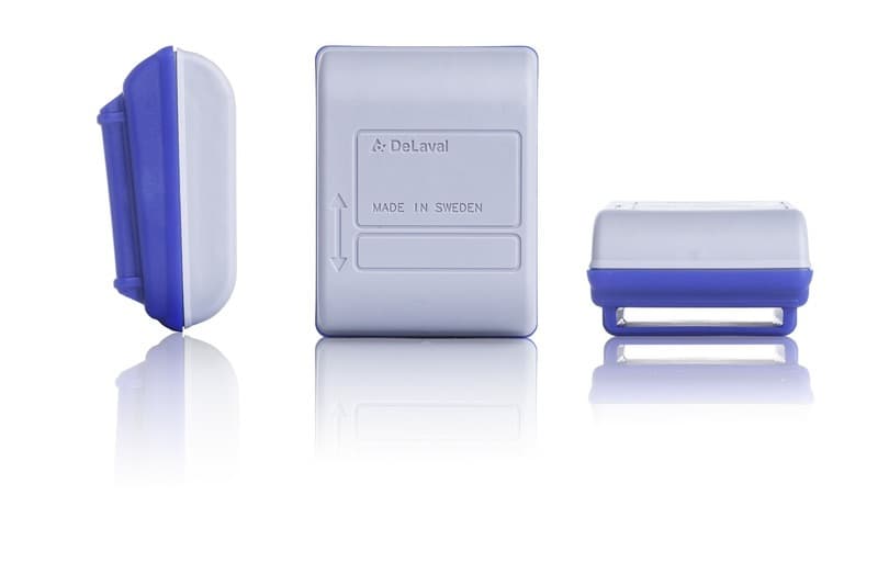
UCS86295081
Feb 18, 2015Cow activity meter system
Equipment Class
DSR - Part 15 Remote Control/Security Device Transceiver