UCSCCM315Control and Communication Module
DeLaval International AB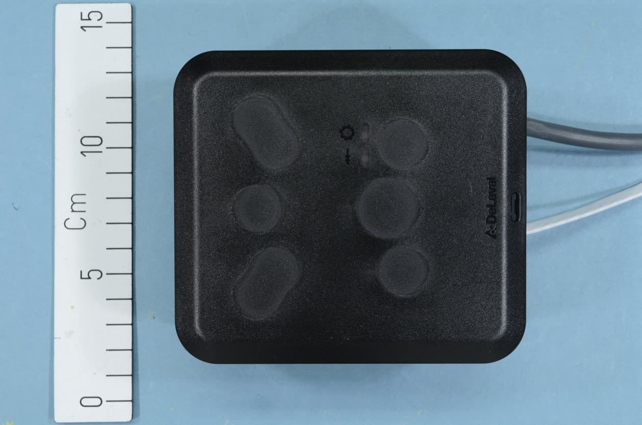
Click to zoom
Application Details
- Equipment Class
- DTS - Digital Transmission System
- Date of Grant
- Sep 17, 2020
- Application Purpose
- Original Equipment
- Date of Application
- Sep 17, 2020
- Equipment Note
- Control and Communication Module
- Frequency Range
- 2402.00000000 - 2480.00000000
- Company
- DeLaval International AB
- Country
- Sweden
Documents & Files
Document Text
Text extracted from the exhibit documents filed with the FCC. Open a document above to read the original.
Users Manual
Preliminary 941322_VMS Instruction Book 2006.pdf2009-09-07 No.NameRangeDefaultDescription/optionsNo.NameRangeDefaultDescription/options 0 = no acidic cleaning0 = no acidic cleaning 1 = one alkaline, one acidic cleaning1 = one alkaline, one acidic cleaning 2 = two alkaline, one acidic cleaning2 = two alkaline, one acidic cleaning 3 = etc.3 = etc. Maintenance an calibration The following points are important to sustain correct dosing of etergents. Note that these two tasks should be performed by an authorised DeLaval service engineer. •The tubes in the peristaltic pumps should be replaced at least two times a year. •The dosing volume (P6-P8) of the detergent pumps should be checked every third month. The dosing capacity (P32-P34) may need to be adjusted. Starting cleaning or rinsing from the touch screen Note: Any ongoing backflush process must first be finished before cleaning or rinsing can be started. 1. Ensure that the milking station is in manual mode. 2. Remove any cow that might be in the milking station. After treatment window Note: Both gates should be closed to prevent a cow from entering before the system cleaning has been started. Closing and opening gates is done in the Stall control window. 3. Press the tab After Treatment on the touch screen to display the After treatment window. 4. In the After treatment window, press the Cleaning and Rinsing button. This will open the Cleaning and rinsing window. DeLaval milking automation MA200 (Test installation) Instruction Book © DeLaval 2019. 2019-05-31, Version 1Original instruction Preliminary 941322_VMS Instruction Book 2006.pdf2009-09-07 No.NameRangeDefaultDescription/optionsNo.NameRangeDefaultDescription/options 0 = no acidic cleaning0 = no acidic cleaning 1 = one alkaline, one acidic cleaning1 = one alkaline, one acidic cleaning 2 = two alkaline, one acidic cleaning2 = two alkaline, one acidic cleaning 3 = etc.3 = etc. Maintenance an calibration The following points are important to sustain correct dosing of etergents. Note that these two tasks should be performed by an authorised DeLaval service engineer. •The tubes in the peristaltic pumps should be replaced at least two times a year. •The dosing volume (P6-P8) of the detergent pumps should be checked every third month. The dosing capacity (P32-P34) may need to be adjusted. Starting cleaning or rinsing from the touch screen Note: Any ongoing backflush process must first be finished before cleaning or rinsing can be started. 1. Ensure that the milking station is in manual mode. 2. Remove any cow that might be in the milking station. After treatment window Note: Both gates should be closed to prevent a cow from entering before the system cleaning has been started. Closing and opening gates is done in the Stall control window. 3. Press the tab After Treatment on the touch screen to display the After treatment window. 4. In the After treatment window, press the Cleaning and Rinsing button. This will open the Cleaning and rinsing window. Preliminary 941322_VMS Instruction Book 2006.pdf2009-09-07 No.NameRangeDefaultDescription/optionsNo.NameRangeDefaultDescription/options 0 = no acidic cleaning0 = no acidic cleaning 1 = one alkaline, one acidic cleaning1 = one alkaline, one acidic cleaning 2 = two alkaline, one acidic cleaning2 = two alkaline, one acidic cleaning 3 = etc.3 = etc. Maintenance an calibration The following points are important to sustain correct dosing of etergents. Note that these two tasks should be performed by an authorised DeLaval service engineer. •The tubes in the peristaltic pumps should be replaced at least two times a year. •The dosing volume (P6-P8) of the detergent pumps should be checked every third month. The dosing capacity (P32-P34) may need to be adjusted. Starting cleaning or rinsing from the touch screen Note: Any ongoing backflush process must first be finished before cleaning or rinsing can be started. 1. Ensure that the milking station is in manual mode. 2. Remove any cow that might be in the milking station. After treatment window Note: Both gates should be closed to prevent a cow from entering before the system cleaning has been started. Closing and opening gates is done in the Stall control window. 3. Press the tab After Treatment on the touch screen to display the After treatment window. 4. In the After treatment window, press the Cleaning and Rinsing button. This will open the Cleaning and rinsing window. Safety precautions DeLaval milking automation MA200 (Test installation) 1 Foreword The safety and operational instructions must be observed by any person involved with the use or operation of this equipment. Under no circum- stances must the equipment be used if it is dam- aged or if the operation of the equipment is not completely understood. 2 Disclaimer The information, instructions and parts listed are applicable and current on the date when issued. DeLaval reserves the right to make changes with- out notice. 3 Definitions of admonishments Admonishments are safety related warning mes- sages. Admonishments provide important information intended to prevent incorrect or hazardous use of equipment, machinery or software, and support risk assessment. The following list defines the different types of admonishments used in DeLaval documentation: Danger: Refers to imminent and severe risk. Failure to comply with instruction will result in serious injury or death. Warning: Refers to a potential but severe risk. Failure to comply with instruction could result in injury or death. Caution: Refers to a limited risk. Failure to com- ply with instruction could result in minor injury. Mandatory: Refers to an action or behaviour which is essential to safe and successful use of the equipment. Prohibited: Refers to an action or behaviour which is incompatible to safe and successful use of the equipment. DeLaval milking automation MA200 (Test installation) Safety precautions © DeLaval 2019. 2019-05-31, Version 13 (62) Preliminary 941322_VMS Instruction Book…
Text truncated - open the document above for the full version.
Users Manual
Manual 1 (8) Subject Doc. Id Simple version of SRRC manual-1 Replacing Issued by/Department Approved by/Department Date Thorbjörn Persson D&E 2020-09-16 Recipient Information class Public Simple version of SRRC manual 1 Applicant Applicant name: DeLaval International AB Gustaf De Lavals väg 15 Sweden 2 Type Model Type model: CCM315 - Control and communication module with Bluetooth BLE PVS100 - Pulsation and vacuum sensor with Bluetooth BLE 3 Safety precautions 3.1 Note to operator It is the operator's responsibility to see that any person involved with the use or operation of this equipment follows all safety and operational instructions. Under no circumstances should this equipment be used if the equipment is faulty or the operator does not completely understand the operation of the equipment. 3.2 Disclaimer The information, instructions and parts listed are applicable and current on the date when issued. DeLaval reserves the right to make changes without notice. 3.3 Definitions of admonishments Admonishments are safety related warning messages. Admonishments provide important information intended to prevent incorrect or hazardous use of equipment, machinery or software, and support risk assessment. The following list defines the different types of admonishments used in DeLaval documentation: Danger: Refers to imminent and severe risk. Failure to comply with instruction will result in serious injury or death. Warning: Refers to a potential but severe risk. Failure to comply with instruction could result in injury or death. Subject Doc. Id Simple version of SRRC manual Information class Internal 2 (8) Caution: Refers to a limited risk. Failure to comply with instruction could result in minor injury. Mandatory: Refers to an action or behavior which is essential to safe and successful use of the equipment. Prohibited: Refers to an action or behavior which is incompatible to safe and successful use of the equipment. Note! Is intended to draw attention to specific points of importance in the text and advice to prevent equipment damage. Subject Doc. Id Simple version of SRRC manual Information class Internal 3 (8) 3.4 Safety regulations Subject Doc. Id Simple version of SRRC manual Information class Internal 4 (8) 3.5 Safety labels on the equipment Subject Doc. Id Simple version of SRRC manual Information class Internal 5 (8) 4 Regulatory 4.1 FCC Statement NOTE: This equipment has been tested and found to comply with the limits for a Class A digital device, pursuant to part 15 of the FCC Rules. These limits are designed to provide reasonable protection against harmful interference when the equipment is operated in a commercial environment. This equipment generates, uses, and can radiate radio frequency energy and, if not installed and used in accordance with the instruction manual, may cause harmful interference to radio communications. Operation of this equipment in a residential area is likely to cause harmful interference in which case the user will be required to correct the interference at his own expense. Changes or modifications to the equipment not expressly approved by the party responsible for compliance could void the user's authority to operate the equipment. To comply with FCC/IC RF exposure limits for general population / uncontrolled exposure, the antenna(s) used for this transmitter must be installed to provide a separation distance of at least 20 cm from any persons and must not be co-located or operating in conjunction with any other antenna or transmitter. 4.2 ISED Canada Statement This Device complies with Industry Canada License-exempt RSS standard(s). Operation is subject to the following two conditions: (1) this device may not cause interference, and (2) this device must accept any interference, including interference that may cause undesired operation of the device. Le présent appareil est conforme aux CNR d’Industrie Canada applicables aux appareils radio exempts de licence. L’exploitation est autorisée aux deux conditions suivantes : (1) l’appareil ne doit pas produire de brouillage ; (2) l’appareil doit accepter tout brouillage radioélectrique subi, même si le brouillage est susceptible d’en compromettre le fonctionnement. Subject Doc. Id Simple version of SRRC manual Information class Internal 6 (8) 5 Operating instructions 5.1 Introduction DeLaval InService™ Remote (ISR) is a cloud based asset management system, providing remote monitoring of equipment performance. Keeping equipment optimized at all times is important to maintain good udder health. Sensors are installed on vacuum systems and pulsators, where data and alarms are delivered to both farmer and service technician. The farmer and service technician can, at any time, access the ISR user interface to check the farm status, see historical alarms, configure system, etc. The system can be accessed by using PC, tablet or smart phone. A selectable number of pulsation curves and milking points are saved daily, every 10th milking by default. They can be retrieved and be compared to identify changes indicating potential problems. Three types of messages can be delivered to the farmer/service technician: Alarm (red) – An urgent fault occurred that needs to be corrected immediately. Warning (yellow) – Values over time show a decreasing performance that should be resolved as soon as possible to avoid malfunctions in the near future. Notification (blue) – Configurable notifications from specific digital inputs (currently not in use). If an alarm occurs, a text message and/or e-mail is sent to the recipient, defined by the user. The user can add/remove alarm recipients at any time. Depending on the service agreement, the service technician can either call the customer, or go to the farm, to solve the problem. 5.2 DeLaval InService™ Remote pulsation and vacuum sensor PVS100 Wireless sensors monitor values to find any deviation from the correct levels. If incorrect values are found, an alert is sent to the CCM315 …
Text truncated - open the document above for the full version.
External Photos
EXTERNAL PHOTOS Project no.: 370326 FCC ID: UCSCCM315 Page 1 (2) EXTERNAL PHOTOS Project no.: 370326 FCC ID: UCSCCM315 Page 2 (2)
ID Label/Location Info
This document may constitute acontractual obligation on the part ofDeLaval International AB only to theextent expressly agreed upon. © C O P Y R I G H T D e L a v a l I n t e r n a t i o n a l A B 2 0 1 8 . T h i s d o c u m e n t a n d i t s c o n t e n t s m u s t n o t b e c o p i e d , r e p r o d u c e d , t r a n s m i t t e d o r d i s c l o s e d t o a n y t h i r d p a r t y w i t h o u t t h e c o n s e n t o f D e L a v a l I n t e r n a t i o n a l A B . A3 Version sheets No. of No. Sheet First angle projection Method ISO E Document No. Title LABEL FRONT CONNECTIONS CCM315 D0000095528 1 1 03 EXAMPLE: Adhesive Product name: DeLaval control and communication Module Art No: 2150011470 Model: CCM315 Serial no: XXXXXXX 1 1 1 11 18 19 22 23 7 6 3 2 5 4 1 8 9 10 17 20 21 24 12 3,5 62 52 11 18 19 22 23 7 6 3 2 5 4 1 8 9 10 17 20 21 24 12 ETH ETH QR code 10x10mm includes: Model: CCM315 MAC adress for BLE chip(without colon): variable Electronics article number: 2150011470 Pcba article number: 2150006026 Serial number: variable (Same format as printed serial number) Serial number: xxxxxxx Month Code according to document 956227 Year code according to document 956227 Running number according to document 956227, 5 digits Logo acc. to drawing 988889. X=3,5 mm Text in DeLaval Black (NCS S 5800-N) with white background. Font: Helvetica, height 2,5mm Product name: DeLaval control and communication Module Art No: 2150011470 Model: CCM315 Serial no: HE00568 The label shall fulfill the durability demands of IEC 61010-1. 3
ID Label/Location Info
This document may constitute acontractual obligation on the part ofDeLaval International AB only to theextent expressly agreed upon. © C O P Y R I G H T D e L a v a l I n t e r n a t i o n a l A B 2 0 1 8 . T h i s d o c u m e n t a n d i t s c o n t e n t s m u s t n o t b e c o p i e d , r e p r o d u c e d , t r a n s m i t t e d o r d i s c l o s e d t o a n y t h i r d p a r t y w i t h o u t t h e c o n s e n t o f D e L a v a l I n t e r n a t i o n a l A B . A3 Version sheets No. of No. Sheet First angle projection Method ISO E Document No. Title Type plate CCM 315 D0000095532 1 1 05 7 ±0,3 Text in DeLaval Black (NCS S 5800-N) with white background. Font: Helvetica, height 2mm The label shall fulfill the durability demands of IEC 61010-1 and shall be Self-adhering. Symbols shall be according to standard SS-EN 50419 Adhesive Product name: DeLaval control and communication module Model: CCM315 Power: 24VDC, 5W Electronics article no: 2150011470 Serial no for electronics: FCC ID: UCSCCM315 IC: 6576A-CCM315 www.delaval.com Made by DeLaval China 1. ISO 7000-0434B mark 2. CE mark 3. WEEE symbol according to document 875637 4. GITEKI mark 5 ±0,3 QR code includes: Model: CCM315 MAC adress for BLE chip(without colon): variable Electronics article number: 2150011470 Pcba article number: 2150006026 Serial number: variable (Same format as printed serial number) 10q Serial number: xxxxxxx Month Code according to document 956227 Year code according to document 956227 Running number according to document 956227, 5 digits Outer contour of label. No printed frame. 5 5 ±0,3
Internal Photos
INTERNAL PHOTOS Project no.: 370326 FCC ID: UCSCCM315 Page 1 (1)
RF Exposure Info
FCC ID: UCSCCM315 MPE Calculation for FCC Uncontrolled Environment Formula from page 18 of OET Bulletin 65, Edition 97-01 where:S = power density P = power input to the antenna G = power gain of the antenna in the direction of interest relative to an isotropic radiator R = distance to the center of radiation of the antenna Source Based Time Averaged Duty Cycle is 100% in calculation below Maximum peak output power at antenna input terminal:9.30(dBm) Maximum peak output power at antenna input terminal:0.009(W) Maximum antenna gain:0.00(dBi) Maximum antenna gain:1.000(numeric) Prediction distance:20(cm) Prediction frequency:2402(MHz) Time Averaged Duty Cycle100% MPE limit for uncontrolled exposure at prediction frequency:10.00(W/m^2) Power density at prediction frequency:0.0017(mW/cm^2) Power density at prediction frequency:0.017(W/m^2) Maximum allowable antenna gain:27.71(dBi) Margin of Compliance:27.71(dB) 2 4R PG S p =
Test Report
Report No. 370326-01-R02 Template version: C Nemko Norway Nemko AS, Instituttveien 6, P.O. Box 96 Kjeller, 2027 Kjeller, Norway TEL +47 22 96 03 30 FAX +47 22 96 05 50 EMAIL [email protected] ENTERPRISE NUMBER NO974404532 nemko.com/no Test Report Product Bluetooth LE Control and Communication Module Name and address of the applicant DeLaval International AB P.O. Box 39 SE-14721 Tumba, Sweden Name and address of the manufacturer DeLaval International AB P.O. Box 39 SE-14721 Tumba, Sweden Model CCM315 Rating 24 V DC (from AC/DC power supply 100-240 VAC 50-60 Hz) Trademark DeLaval Serial number / Additional information Bluetooth Low Energy Tested according to FCC Part 15.247 Frequency Hopping Transmitters / Digital Transmission Systems Industry Canada RSS-247, Issue 2 Low Power Licence-Exempt Radiocommunications Devices Order number 370326 Tested in period 2019.07.01 and 2019.10.28 to 2019.10.29 Issue date 2020.09.16 Name and address of the testing laboratory Instituttveien 6 Kjeller, Norway www.nemko.com CAB Number: FCC: NO0001 ISED: NO0470 TEL: +47 22 96 03 30 FAX: +47 22 96 05 50 An accredited technical test executed under the Norwegian accreditation scheme Prepared by [Frode Sveinsen] Approved by [G.Suhanthakumar] This report shall not be reproduced except in full without the written approval of Nemko. Opinions and interpretations expressed within this report are not part of the current accreditation. This report was originally distributed electronically with digital signatures. For more information contact Nemko. TEST REPORT FCC Part 15.247 Report no.: 370326-01-R02 FCC ID: UCSCCM315 IC: 6576A-CCM315 Nemko Norway, Instituttveien 6, Kjeller, Norway Page 2 (48) CONTENTS 1 INFORMATION ......................................................................................................................... 3 1.1 Test Item .................................................................................................................................... 3 1.2 Normal test condition ................................................................................................................. 3 1.3 Test Engineer(s) ........................................................................................................................ 3 1.4 Antenna Requirement ................................................................................................................ 4 1.5 Test Configuration ..................................................................................................................... 4 1.6 Comments ................................................................................................................................. 4 2 TEST REPORT SUMMARY ...................................................................................................... 5 2.1 General ...................................................................................................................................... 5 2.2 Test Summary ........................................................................................................................... 6 3 TEST RESULTS ........................................................................................................................ 7 3.1 Power Line Conducted Emissions ............................................................................................. 7 3.2 Occupied Bandwidth (99% BW)................................................................................................. 8 3.3 DTS Bandwidth ........................................................................................................................ 11 3.4 Peak Output Power .................................................................................................................. 14 3.5 Conducted Emissions at Antenna Connector .......................................................................... 17 3.6 Restricted Bands of operation.................................................................................................. 23 3.7 Radiated Emissions, Band Edge ............................................................................................. 24 3.8 Radiated Emissions, 30 – 1000 MHz ....................................................................................... 26 3.9 Radiated Emissions, 1 – 25 GHz ............................................................................................. 30 3.10 Power Spectral Density (PSD) ................................................................................................. 42 4 Measurement Uncertainty ..................................................................................................... 45 5 LIST OF TEST EQUIPMENT................................................................................................... 46 6 BLOCK DIAGRAM .................................................................................................................. 47 6.1 Power Line Conducted Emission ............................................................................................. 47 6.2 Conducted Tests ...................................................................................................................... 47 6.3 Test Site Radiated Emission .................................................................................................... 48 TEST REPORT FCC Part 15.247 Report no.: 370326-01-R02 FCC ID: UCSCCM315 IC: 6576A-CCM315 Nemko Norway, Instituttveien 6, Kjeller, Norway Page 3 (48) 1 INFORMATION 1.1 Test Item Name DeLaval FCC ID UCSCCM315 Industry Canada ID 6576A-CCM315 Model/version CCM315 Serial number / Hardware identity and/or version 2150011470 Software identity and/or version MTK test software version 1.0 Frequency Range 2402 – 2480 MHz Number of Channels 40 Type of Modulation Digital (GFSK) User Frequency Adjustment None Rated Output Power 0.0084 Watts (Conducted) Type of Power Supply External DC Supply (24.0 V DC ) Antenna Connector …
Text truncated - open the document above for the full version.
Test Setup Photos
TEST SET-UP PHOTOS Project no.: 370326 FCC ID: UCSCCM315 Page 1 (2) Below 1 GHz Radiated Emissions, Above 1 GHz TEST SET-UP PHOTOS Project no.: 370326 FCC ID: UCSCCM315 Page 2 (2) Radiated Emissions, Above 18 GHz Power-line Conducted Emissions Test
Contact Information
Applicant
Susanne Sundstroem(Product Compliance)
Test Firm
Nemko Scandinavia ASTor Erik Pedersen
[email protected]+4798228176
Technical Specifications
| # | Rule Parts | Frequency Range | Power Output |
|---|---|---|---|
| 1 | 15C | 2.40 GHz - 2.48 GHz | 8.40 mW |
Other Applications from DeLaval International AB
UCS2150024802
Jan 02, 2023Farm monitoring Camera FMC- IP1.1 US
Equipment Class
DTS - Digital Transmission System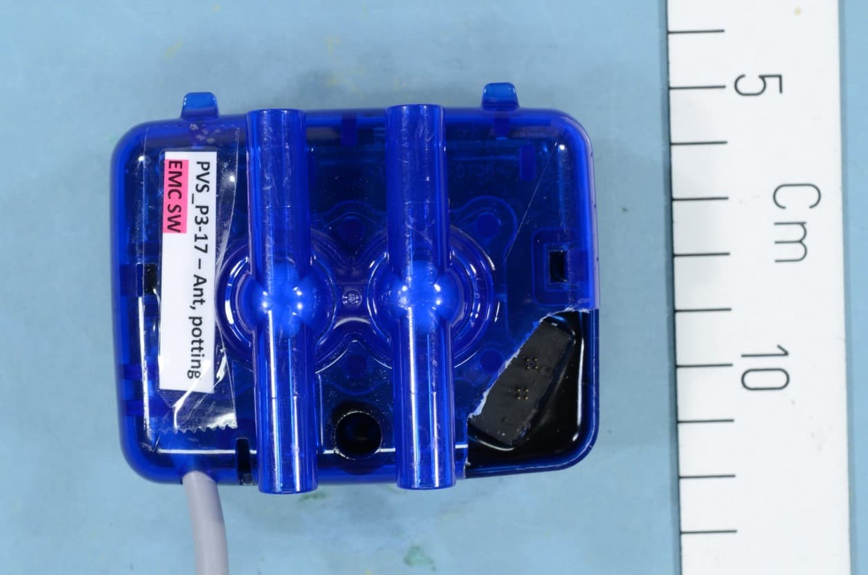
UCSPVS100
Sep 20, 2020Pulsation and u Sensor
Equipment Class
DTS - Digital Transmission System
UCS940663
Jan 03, 2016Electronic identification reader device for dairy cows
Equipment Class
DCD - Part 15 Low Power Transmitter Below 1705 kHz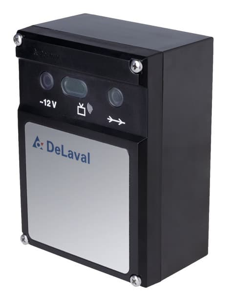
UCS86120691
Feb 23, 2015Cow activity meter system 418 MHz
Equipment Class
DSR - Part 15 Remote Control/Security Device Transceiver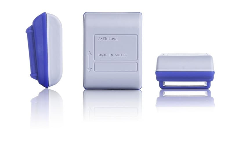
UCS86295081
Feb 18, 2015Cow activity meter system
Equipment Class
DSR - Part 15 Remote Control/Security Device Transceiver