UDATDS-602SBLUETOOTH HEADSET
Guangzhou Tendystar Telecom Co., Ltd.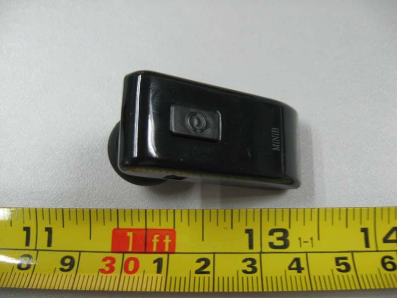
Click to zoom
Application Details
- Equipment Class
- DSS - Part 15 Spread Spectrum Transmitter
- Date of Grant
- Nov 18, 2007
- Application Purpose
- Original Equipment
- Date of Application
- Nov 18, 2007
- Equipment Note
- BLUETOOTH HEADSET
- Frequency Range
- 2402.00000000 - 2480.00000000
- Country
- China
Documents & Files
Document Text
Text extracted from the exhibit documents filed with the FCC. Open a document above to read the original.
Users Manual
Manual Of TDS-602S Introduction The Bluetooth technology is a standard for wireless short distance radio communications. Devices like headset, mobile phone or PDA can communicate with each other without wires within approximately 10 meters. The TDS-602 headset is a wireless headset based on the Bluetooth technology. It supports two profiles: Headset profile and Hands-free profile. It will work with all qualified Bluetooth devices (including headset and PDA) that support the Headset profile or Hands- free profile. It also will allow you to take a call and adjust the volume without touching your mobile phone. Attentions: 1、For the first using or reusing after a long leave, energy of the battery is very low. In this case, the LED indicator will not flash until 10-15 minutes' charging. 2、In order to get the best sound; please adjust the Mic close to the mouth. Charging At the first use, it is suggested to charge the headset for 8 hours at least. After that, it is suggested to charge around 2-3 hours every time. During charging, the LED indicator flashes in red and blue alternately. When charging finishes, the LED indicator flashes in blue only. Be sure to charge the battery with the supplied charger. Charging time should be less than 12 hours. When energy of the battery is extremely poor, LED indicator will not flash in blue at the beginning of charging. Wearing the headset Being with a soft and supple earplug, TDS-602 is very ear- friendly. When hear a call with it, just insert the earplug into an ear. Turning the headset on Keep pressing the TALK button over 2 seconds, and the LED long-twinkles in blue for about 3 seconds, then the device turns on. Turning the headset off Keeping pressing the TALK button of a working TDS-602 over 5 seconds, and the LED goes out after a 2 second- twinkles, then the device turns off. Pairing the headset Pairing is the connection between two Bluetooth devices to exchange data. The operation process as follows: 1. o initiate the pairing, put both the headset and the mobile phone within 1 meter from each other. 2. Make sure you headset is fully charged. 3. Press and hold the multifunction button until the red and blue indicator light flashes red and blue alternatively. 4. Follow the phone instruction, active the Bluetooth function on your mobile phone. 5. Active the discover mode on your mobile phone. And select “TDS-602” character. 6. Follow the mobile phone instruction, input the PIN code “0000”, and press ”OK” to complete the pairing. When the pairing is complete, the red and blue indicator light will flashing in blue for 5 times, and you will hear a long “beep” from the speaker. 7. Press “Enter” to return to the main menu of your mobile phone. Now you can ready to use your headset to make or receive calls. Caution: If the Pairing is not finished within 2 minute after you start the pairing mode, the red and blue indicator light will flashing in blue, and you can hear a “deep” from the speaker. Please pairing the headset with your mobile phone again by repeat step 2-7. Making a call If your mobile phone is featured with voice recognition function and the phone number is recorded on the contact list of mobile phone, you can make a call directly from the headset. Press the TALK button and speak the contact name you want to call. Make sure the voice tags have been recorded into the mobile phone. Redial the last number Double click the TALK button and keep pressing it for over 2 seconds, release the button until you hear a beep. Ending a call To end a call, press the TALK button during a call. Hearing a call When a call comes, the LED will twinkle continually. Press down the TALK button to hear the call. The LED twinkles 2 times continuously once the call gets through, then, it twinkles once every 12-15 seconds. Rejecting a call When a call gets in, double press the TALK button, the call is refused. Adjusting the volume Press upside of the lateral button, volume increases, while press the downside of it, volume decreases. Muting the volume During talking, press the TALK button, the earphone gets into mute. Press the TALK button again, voice status resumes. Transferring calls During a call, press the TALK button for 5 seconds to the call will be transferred to mobile phone. The above function is available only after the headset is paired with the mobile phone. FAQ After pairing, sometimes, you couldn't use the Bluetooth headset with your mobile phones, such as Nokia Mobile phones with S60 system and Sony-Ericsson mobile phones, you need to pair them again and build connection. Sometimes, you couldn't find the Bluetooth Headset on your mobile phones. Please re-charge Bluetooth headsets or mobile phones. The connection breaks in the following situations: 1. Poor power in the mobile phone or headset. 2. The distance between mobile phone and headset is more than the operation range. 3. Too much environmental interference (such as electromagnetism, electric wave or object obstruct, etc). At the first use or energy of the battery is extremely poor, the LED indicator will not flash. After 2 hours charging, the LED indicator will work. Specification: 1) Bluetooth Core:CSR 2) Version:V2.0 Class2 3) Transmission distance: 10 meters 4) Point to point pairing 5) Weight:8G 6) Standby:160 hours 7) Continuously Talking Time:6 hours 8) Charging Time:2hours 9) Code: 0000 10) Battery: Chargeable Li Battery(75mmA) 11) Adaptor: 5V DC 100-240V AC with adaptor 12) Working Temperature: -10 - 55°C 13) Storage Temperature: -20 - 60°C FCC Caution: This device complies with Part 15 of the FCC Rules. Operation is subject to the following two conditions: (1) this device may not cause harmful interference, and (2) this device must accept any interference received, including interference that may cause undesired operation. FCC Notes: The manufacturer is not responsible for and radio or TV interference caused by unauthorized modifications to this equipment. Such modifications could void the user…
Text truncated - open the document above for the full version.
Block Diagram
Block Diagram Battery 2402-2480MHz Antenna Microphone Circuit LED Button Microphone U1 BC413159A EEPROM CRYSTAL 16MHz Charger
External Photos
GUANGZHOU TENDYSTAR TELECOM CO., LTD. Model: TDS-602S Report No.: STR07118035I FCC PART 15.247 EXHIBIT 2 - EUT EXTERNAL PHOTOGRAPHS EUT View 1 EUT View 2
ID Label/Location Info
GUANGZHOU TENDYSTAR TELECOM CO., LTD. Model: TDS-602S Report No.: STR07118035I FCC PART 15.247 EXHIBIT 1- PRODUCT LABELING Proposed FCC ID Label Format FCC ID: UDATDS-602S Specifications : Labels are printed in indelible ink on permanent adhesive silk-screened onto the EUT or shall be affixed at a conspicuous location on the EUT. Proposed Label Location on EUT FCC ID Label Location
ID Label/Location Info
GUANGZHOU TENDYSTAR TELECOM CO., LTD. Model: TDS-602S Report No.: STR07118035I FCC PART 15.247 EXHIBIT 1- PRODUCT LABELING Proposed FCC ID Label Format FCC ID: UDATDS-602S Specifications : Labels are printed in indelible ink on permanent adhesive silk-screened onto the EUT or shall be affixed at a conspicuous location on the EUT. Proposed Label Location on EUT FCC ID Label Location
Internal Photos
GUANGZHOU TENDYSTAR TELECOM CO., LTD. Model: TDS-602S Report No.: STR07118035I FCC PART 15.247 EXHIBIT 3 - EUT INTERNAL PHOTOGRAPHS EUT Housing and Board View 1 Solder Board-Component View 1 GUANGZHOU TENDYSTAR TELECOM CO., LTD. Model: TDS-602S Report No.: STR07118035I FCC PART 15.247 Solder Board-Component View 2
Operational Description
Circuit Description U1 (BC413159A) use CSR chipset, this chipset provides a fully compliant Bluetooth system to V2.0+EDR of the specification for data and voice communications. It integrated switch-mode regulator and battery charger with programmable. SW1, K3 are human control interface, It control the headset difference operation The RF circuit is consist of ∏ type filter and antenna. The U1 (BC413159A) main chip supporting by a crystal of 16MHz The audio signal pass through the Mic circuit, then enter to the U1, after the main chip analyzer and modulator, with the CSR Bluetooth software stack, it provides a fully compliant Bluetooth system of the specification for data and voice communications, then transmitting through the antenna with 2402 to 2480MHz.
Schematics
12345678 A B C D 8 7654321 D C B A Title NumberRevisionSize D Date:31-Oct-2007Sheet of File:D:\orora\sch\TD03.ddbDrawn By: V D D _ C O R E E 1 1 V D D _ U S B L 1 1 V D D _ A N A L 1 V D D _ A N A 1 L 5 V D D _ V C O H 2 V D D _ P I O B 1 V D D _ R A D I O C 1 V D D _ P A D S D 1 1 V D D _ M E M B 6 V D D _ M E M B 8 V D D _ M E M J 7 V D D _ M E M K 8 L X A 6 V R E G _ E N H 3 P I O [ 9 ] A 4 P I O [ 0 ] A 1 P I O [ 1 ] B 2 P I O [ 2 ] A 2 L E D [ 0 ] A 9 L E D [ 1 ] A 1 0 SPI_CLK C11 SPI_CSB B9 SPI_MISO B11 SPI_MOSI C9 UART_TX K9 UART_RX K10 UART_RTS L8 UART_CTS K11 PIO[3] B3 PIO[6] F11 PIO[7] G9 PIO[8] A5 PIO[10] B4 PIO[11] A3 AUX_DAC C3 PCM_CLK H11 PCM_OUT G11 PCM_IN J11 PCM_SYNC H9 TEST[1] K7 TEST[2] J8 TEST_EN C10 VREG_OUT K1 AIO[2] L7 X T A L _ I N L 4 X T A L _ O U T K 4 P I O [ 4 ] F 9 M I C _ P L 2 M I C _ N L 3 S P K R _ N J 1 S P K R _ P J 2 V S S _ M E M C 7 V S S _ M E M C 5 V S S _ A N A J 3 U S B _ D N L 9 U S B _ D P L 1 0 B A T _ N A 7 V S S E 3 V S S _ C O R E E 9 V S S _ P A D S 4 C 4 V S S _ P A D S 3 C 8 V S S _ P A D S 2 D 9 V S S _ P A D S 1 J 9 V S S _ V C O G 1 V S S _ V C O G 2 V S S _ A N A K 2 V S S _ A N A K 3 V S S _ A N A J 5 V S S _ A N A J 4 V S S _ R A D I O F 2 V S S _ R A D I O E 2 V S S _ R A D I O D 2 V S S _ R A D I O C 2 TX_A F1 TX_B E1 RX_IN D1 VDD_CHG A11 PIO[5] F10 RESETB D10 AIO[0] J6 AIO[1] L6 BAT_P A8 VREG_IN H1 U1 BC413159A C6 10P C8 2P2 R1 2R2 C1 103 C2 103 P I O 9 P I O 0 P I O 1 P I O 2 L E D 0 L E D 1 C11 103 12 34 Y1 16MHz C9 10P C10 3P3 SP+ SP- MIC+ MIC- PIO4 AIO1 RESETB VBAT +5V PIO5 PIO[3] PIO6 PIO7 PIO8 PIO10 PIO11 PCM_CLK PCM_OUT PCM_IN PCM_SYNC UART_CTS UART_RTS UART_RX UART_TX SPI_MOSI SPI_MISO SPI_CSB SPI_CLK R82.2K R9 2.2K R10 2.2K + 1 . 8 V PIO8 PIO6 PIO7 SCL 6 GND 4 SDA 5 VCC 8 WP 7 A0 1 A1 2 A2 3 U2 AT24C32 K3 VOL+ K2 VOL- +1.8VPIO1 PIO2 C14 15P SW1 ON/OFF PIO9 LED2 Blue LED1 RED R18 331 L E D 0 L E D 1 R5 220K 1% AIO0 VBAT R4 150K 1% R19 101 Q2 3904 Q3 3904 R15 47K PIO10 R13 47K CG C16 105 P I O 4 VIN 1 GND 2 SHDN 3 BYP 4 VOUT 5 U3 RT9167-2.7V C15 103 R11 2.2K L4 15nH C17 15P M I C + M I C - MIC1 -42dB VBAT BAT 3.6V +1.8V1 2 3 4 5 6 J1 SPI SPI-MISO SPI-CSB SPI_MOSI SPI_CLK G 0 5V 1 D- 2 D+ 3 G 4 G 0 J3 CHANG C19 105 R17 2R2 +5V RESETB R16 47K Q1 3904 + 1 . 8 V R12 220K 1% C22 105 CG CG SP+ SP- L6 33uH +1.8V SP1 C5 15P C4 4.7uF E N R2 RES2 L3 15uH + 1 . 8 V ANTENNA C7 2P AIO0 C12 473 C13 473 C18 475 R21 10R C21 103 R3 2.2K R6 47K R7 47K VBATEN R22 220K R20 120K 5 V PIO5 VDD 1 VDD 2 VCC 3 GND 4 NC 5 NC 6 VM 7 VM 8 U4 CR6002 C20 104 VBAT C3 5P6 DC 6 Unbalanced 5 Balanced 3 Balanced 1 N C 7 G N D 4 G N D 2 G N D 8 T1 COMPONENT_1 BT? BATTERY VBAT R22 0R
Test Report
GUANGZHOU TENDYSTAR TELECOM CO., LTD MODEL: TDS-602S Report No.: STR07118035I Page 1 of 24 FCC PART 15.247 FCC Part 15C Measurement and Test Report For GUANGZHOU TENDYSTAR TELECOM CO., LTD. Rm1701-1702, New Century Commercial Trade Center, #2-6 Hong De Road, Haizhu District, Guangzhou, Guangdong, China FCC ID: UDATDS-602S Report Concerns: Original Report Equipment Type: Bluetooth Headset Model: TDS-602S Report No.: STR07118035I Test/Witness Engineer: Lahm Peng Test Date: 2007-11-13 to 2007-11-16 Prepared By: Shenzhen SEM.Test Compliance Service Co., Ltd Room 609-610, Baotong Building, Baomin 1 st Road, Baoan District, Shenzhen, Guangdong, P.R.C. (518133) Approved & Authorized By: Jandy So / PSQ Manager Note: This test report is limited to the above client company and the product model only. It may not be duplicated without prior permitted by SEM.Test Compliance Service Co., Ltd . GUANGZHOU TENDYSTAR TELECOM CO., LTD MODEL: TDS-602S Report No.: STR07118035I Page 2 of 24 FCC PART 15.247 TABLE OF CONTENTS 1. GENERAL INFORMATION ...................................................................................................................................3 1.1 PRODUCT DESCRIPTION FOR EQUIPMENT UNDER TEST (EUT)...............................................................................3 1.2 TEST STANDARDS..................................................................................................................................................3 1.3 RELATED SUBMITTAL(S)/GRANT(S) .......................................................................................................................3 1.4 TEST METHODOLOGY............................................................................................................................................4 1.5 TEST FACILITY.......................................................................................................................................................4 1.6 EUT EXERCISE SOFTWARE....................................................................................................................................4 1.7 ACCESSORIES EQUIPMENT LIST AND DETAILS.......................................................................................................4 1.8 EUT CABLE LIST AND DETAILS.............................................................................................................................4 2. SUMMARY OF TEST RESULTS ...........................................................................................................................5 3. §15.203 - ANTENNA REQUIREMENT..................................................................................................................6 3.1 STANDARD APPLICABLE........................................................................................................................................6 3.2 TEST RESULT.........................................................................................................................................................6 4. NUMBER OF HOPPING CHANNELS AND CHANNEL SPACING .................................................................7 4.1 STANDARD APPLICABLE........................................................................................................................................7 4.2 TEST EQUIPMENT LIST AND DETAILS.....................................................................................................................7 4.3 TEST PROCEDURE...................................................................................................................................................7 4.4 ENVIRONMENTAL CONDITIONS..............................................................................................................................7 4.5 SUMMARY OF TEST RESULTS/PLOTS......................................................................................................................8 5. DWELL TIME OF A HOPPING CHANNEL ......................................................................................................10 5.1 STANDARD APPLICABLE......................................................................................................................................10 5.2 TEST EQUIPMENT LIST AND DETAILS...................................................................................................................10 5.3 TEST PROCEDURE.................................................................................................................................................10 5.4 ENVIRONMENTAL CONDITIONS............................................................................................................................10 5.5 SUMMARY OF TEST RESULTS/PLOTS....................................................................................................................11 6. 20-DB BANDWIDTH ..............................................................................................................................................13 6.1 STANDARD APPLICABLE......................................................................................................................................13 6.2 TEST EQUIPMENT LIST AND DETAILS...................................................................................................................13 6.3 TEST PROCEDURE.................................................................................................................................................13 6.4 ENVIRONMENTAL CONDITIONS............................................................................................................................13 6.5 SUMMARY OF TEST RESULTS/PLOTS....................................................................................................................13 7. POWER OUTPUT.................................................................................................................................................…
Text truncated - open the document above for the full version.
Test Setup Photos
GUANGZHOU TENDYSTAR TELECOM CO., LTD. Model: TDS-602S Report No.: STR07118035I FCC PART 15.247 EXHIBIT 4 - TEST SETUP PHOTOGRAPHS Conducted Emission Test Setup Radiated Emission Test Setup (Above 1GHz) GUANGZHOU TENDYSTAR TELECOM CO., LTD. Model: TDS-602S Report No.: STR07118035I FCC PART 15.247 Radiated Emission Test Setup (Below 1GHz)
Contact Information
Applicant
Fang Zhou(General Manager)
Test Firm
Solid Industrial Co., Ltd.Yang Dengfang
Technical Specifications
| # | Rule Parts | Frequency Range | Power Output |
|---|---|---|---|
| 1 | 15C | 2.40 GHz - 2.48 GHz | 0.00 µW |
Other Applications from Guangzhou Tendystar Telecom Co., Ltd.

UDATDS-801
Dec 18, 2006BLUETOOTH HEADSET
Equipment Class
DSS - Part 15 Spread Spectrum Transmitter
UDAE2
Jul 06, 2006BLUETOOTH HEADSET
Equipment Class
DSS - Part 15 Spread Spectrum Transmitter