UDV-0606020060001GSM/GPRS TRI-BAND MODULE
Shanghai Simcom Ltd.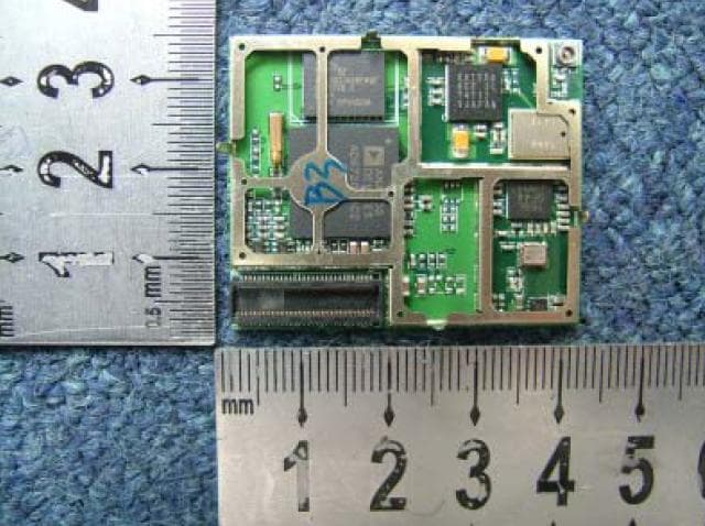
Click to zoom
Application Details
- Equipment Class
- PCB - PCS Licensed Transmitter
- Date of Grant
- Aug 02, 2006
- Application Purpose
- Original Equipment
- Date of Application
- Aug 02, 2006
- Equipment Note
- GSM/GPRS TRI-BAND MODULE
- Frequency Range
- 824.20000000 - 848.80000000
- Company
- Shanghai Simcom Ltd.
- Country
- China
Documents & Files
Document Text
Text extracted from the exhibit documents filed with the FCC. Open a document above to read the original.
Users Manual
GPRS Startup V01.00 SIMCOM Document Name: GPRS Startup Version: 01.00 Date: DocId: GPRS Startup_V01.00 Status: Created General Notes Simcom offers this information as a service to its customers, to support application and engineering efforts that use Simcom products. The information provided is based upon requirements specifically provided to Simcom by the customers. Simcom has not undertaken any independent search for additional relevant information, including any information that may be in the customer’s possession. Furthermore, system validation of this Simcom product within a larger electronic system remains the responsibility of the customer or the customer’s system integrator. All specifications supplied herein are subject to change. Copyright This document contains proprietary technical information which is the property of SIMCOM Limited., copying of this document and giving it to others and the using or communication of the contents thereof, are forbidden without express authority. Offenders are liable to the payment of damages. All rights reserved in the event of grant of a patent or the registration of a utility model or design. All specification supplied herein are subject to change without notice at any time. GPRS Startup_V01.00 Page 1 of 13 GPRS Startup V01.00 SIMCOM SCOPE Thanks you select SIMCOM GSM/GPRS module. This product has standard AT command interface, and can provide GSM call, short message and GPRS net services, etc. Please read this user guide carefully. You can realize the powerful function and the easy operation method of the module. This module is used in voice or data communication mainly. We are not charge with the duty of personal injury and property loss for the custom abnormal operation. Please design the corresponding product according to the technical specification and reference in the handbook. And note the general safe item when use mobile product especially GSM product. This document is subject to change without notice at any time. This document suits for SIM100S, SIM100F, SIM100C, SIM200, SIM300 module. GPRS Startup_V01.00 Page 2 of 13 GPRS Startup V01.00 SIMCOM Revision History Chapter Page What is new GPRS Startup_V01.00 Page 3 of 13 GPRS Startup V01.00 SIMCOM Contents 1. Introduction...................................................................................................................... 5 1.1 References............................................................................................................... 5 1.2 Abbreviations........................................................................................................... 5 2. What you need.................................................................................................................. 6 2.1 GPRS settings from your network provider............................................................ 6 2.2 Modem installation and configuration..................................................................... 6 2.3 Dial-Up network installation and configuration...................................................... 6 3 Setting up a Windows modem driver................................................................................ 7 3.1 Adding a new modem.............................................................................................. 7 3.2 Configuring the modem driver................................................................................ 9 4 Setting up the Dial-Up network....................................................................................... 10 4.1 Adding a new connection...................................................................................... 10 4.2 Configuring the setting .......................................................................................... 11 5 Getting Started................................................................................................................. 12 GPRS Startup_V01.00 Page 4 of 13 GPRS Startup V01.00 SIMCOM 1. Introduction This document describes how to establish a PPP connection with Microsoft Windows NT4.0 using the prototype of GSM/GPRS. Configurations and settings for other operating systems (Windows 95/98) may slightly differ, but the general proceeding is similar. 1.1 References /1/ SIMCOM_ATC /2/ Request for Comments: 1661 - The Point-to-Point Protocol (PPP) /3/ Request for Comments: 1994 - PPP Challenge Handshake Authentication Protocol (CHAP) 1.2 Abbreviations APN Access Point Name CHAP Challenge Handshake Authentication Protocol CID Context Identity DHCP Dynamic Host Configuration Protocol DNS Domain Name Server DSB Developer Support Box GPRS General Packet Radio Service GSM Global System of Mobile Communication IP Internet Protocol OS Operating System PDP Packet Data Protocol PIN Personal Identification Number PPP Point to Point Protocol QoS Quality of Service RAS Remote Access Service ROM Read Only Memory SIM Subscriber Identity Module TCP Traffic Control Protocol GPRS Startup_V01.00 Page 5 of 13 GPRS Startup V01.00 SIMCOM 2. What you need 2.1 GPRS settings from your network provider Before you can set up your device to access the GPRS network, contact your network provider to obtain the GPRS service . 2.2 Modem installation and configuration You will need to set up the modem driver. Follow the steps in chapter 3. Note: Administrator rights for the operation system may be needed in order to install modem driver. Connect your local system administrator for advice. 2.3 Dial-Up network installation and configuration You will need to set up the Dial-Up network. Follow the steps in chapter 4. GPRS Startup_V01.00 Page 6 of 13 GPRS Startup V01.00 SIMCOM 3 Setting up a Windows modem driver 3.1 Adding a new modem If no standard 19200bps modem has been installed, add a new standard modem to the modem section of the control panel. Click Start -> Setting -> Control Panel -> Phone and Modem option -> Modem -> add GPRS Startup_V01.00 Page 7 of 13 GPRS Startup V01.…
Text truncated - open the document above for the full version.
Users Manual
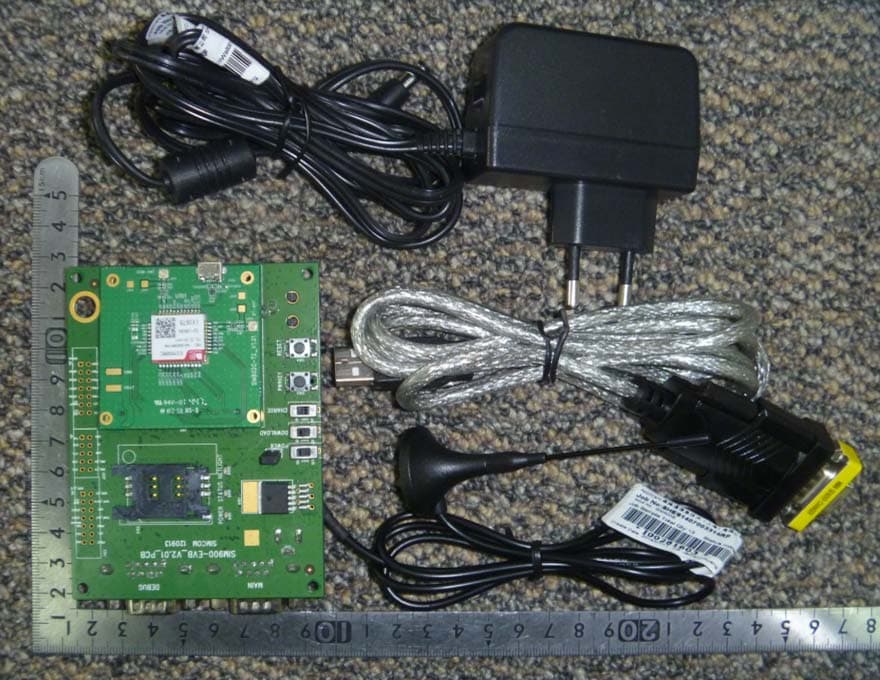
SIM300 User Manual Document Name: SIM300 User Guide Version: 1.00 Date: 2006-6-18 DocId: SIM300 User Guide_V1.00 Status: Release General Notes Simcom offers this information as a service to its customers, to support application and engineering efforts that use Simcom products. The information provided is based upon requirements specifically provided to Simcom by the customers. Simcom has not undertaken any independent search for additional relevant information, including any information that may be in the customer’s possession. Furthermore, system validation of this Simcom product within a larger electronic system remains the responsibility of the customer or the customer’s system integrator. All specifications supplied herein are subject to change. Copyright This document contains proprietary technical information which is the property of SIMCOM Limited., copying of this document and giving it to others and the using or communication of the contents thereof, are forbidden without express authority. Offenders are liable to the payment of damages. All rights reserved in the event of grant of a patent or the registration of a utility model or design. All specification supplied herein are subject to change without notice at any time. Copyright © SIMCOM Limited. 2006 Contents 1 SIM300 EVB and accessories ................................................................................................4 1.1SIM300 EVB................................................................................................................4 1.2 accessories...................................................................................................................5 2 EVB and accessory equipment...............................................................................................5 3 Operation................................................................................................................................6 3.1 Tune up procedure.......................................................................................................6 3.2 Setup the phone call ....................................................................................................6 3.3 GPRS start-up ...........................................................................................................12 4 AT command ........................................................................................................................12 5 FCC Requirements ...............................................................................................................12 6 FCC RF exposure requirements ...........................................................................................13 1 SIM300 EVB and accessories 1.1SIM300 EVB Figure 1: EVB TOP view Figure 2: EVB BOTTOM view A: SIM300 module interface B: SIM card interface C: headset interface D: Download switch, turn on or off download function E: VBAT switch, switch the voltage source from the adaptor or external battery F: PWRKEY key, turn on or turn off SIM300 G: buzzer H: expand port, such as keypad port, main and debug serial port, display port I: MAIN serial port for downloading, AT command transmitting, data exchanging J: DEBUG serial port K: hole for fixing the antenna L: source adapter interface M: light N: hole for fixing the SIM300 O: headphones interface 1.2 accessories A: antenna B: antenna transmit line C: headset D: 5V DC source adapter E: serial port line 2 EVB and accessory equipment At normal circumstance, the EVB and its accessory are equipped as the nether figure: Figure 3: EVB and accessory equipment 3 Operation Firstly,please equip the module and accessories as the figure 3: 3.1 Tune up procedure 1)switching the S1 switch to off state, S2 switch to ON state; 2) Press the PWRKEY button for about 1 second, then the LED glint,and the module is tuning up successfully; 3.2 Setup the phone call Please setup a HyperTerminal(AT command windows) step by step: Step1,setup the HyperTerminal connect: Step 2:Parameter setting(set the PC serial port and band rate) Step 3:power on the module and key in the AT command: 1) power on the module; 2) key in the “AT” and enter,if the “OK” is feedback,it indicates that the module connecting to the PC is successful; 3) Key in the “AT+CSQ” and enter,if the feedback is as below,it indicates that the module connecting to the NET is successful; 4) Key in the “ATD112;” and enter to set a phone call,and key in “AT H” to hang up the call; 3.3 GPRS start-up (Please see the GPRS start-up document) 4 AT command (please see the AT command document) 5 FCC Requirements Please note: 1)The SIM300 must be designed for mobile or fixed operation only (Portable is not permitted and requires separate approval); 2)When the SIM300 is integrated into a final product, the FCC ID label must be visible through a window on the final device or it must be visible when an access panel,door or cover is easily removed。 If not,a second label must be placed on the outside of the final device that contains the following text: “Contains FCC ID: UDV-06060200600001” SIM300 FCC label is shown as: 6 FCC RF exposure requirements To allow compliance with the FCC RF exposure requirements, the SIM300’s maximum output power is 33dBm in GSM900 band and 30dBm in DCS1800/PCS1900 band,and the maximum antenna gain is 3dBi and the minimum cable loss is 0.5dB。The antenna(s) used for this transmitter must be installed to provide a separation distance of at least 20 cm from all persons and must not be co-located or operating in conjunction with any other antenna or transmitter。
Block Diagram
HARDWARE FRAME
External Photos
External Photos and Internal Photos of the SIM 300:
ID Label/Location Info
Label Sample of the SIM300: Front View of the SIM300: Back View of the SIM300 and Lable Location Lable Location
Internal Photos
External Photos and Internal Photos of the SIM 300:
Parts List/Tune Up Info
SIM300 BOM List No priority part number part type part description amount part location number 1 A 1100071007 MCR01-MZS-J-000 Resistor 0R(0402) 8 R1001,R1003,R2003,R2006,R2103,R507,R505, R1029 B 1100071767 CR1/16S 000J V 2 A 1100719007 MCR01MZSJ222 Resistor 2.2K(0402) 2 R2004,R2005 3 A 1100059007 MCR01-MZS-J-104 Resistor 100K(0402) 4 R2002,R501,R503,R504 B 1100059767 CR1/16S104 J V 4 A 1100758708 NCP15XH103F03RC 10K NTC Resistor 1 R2015 5 A 1210818708 GRM1555C1H160JZ01 Capacitor 16pF(0402) 3 C2004,C2021,C2023 6 A 1210734702 CM05CG220J50AH Capacitor 22pF(0402) 6 C2011, C1004,C1017-1018,C1012,C1038 B 1210734111 C1005C0G1H220JT 7 A 1210738111 C1005C0G1H470JT Capacitor 47pF(0402) 5 C1001,C1068,C1022,C1029,C1030 B 1210738702 CM05CG470J50AH 8 A 1210828708 GRM1555C1H750JZ01D Capacitor 75pF(0402) 10 C2017,C2018,C2022,C2024,C2025,C2026,C2027, C2028,C2031,C2032 9 A 1210754702 CM05X7R103K16AH Capacitor 10nF(0402) 5 C2034,C1040,C1069,C1054,C1050 B 1210754111 C1005X7R1E103KT 10 A 1210757702 CM5X5R104K10AH Capacitor 100nF(0402) 21 C2001-2003,C2005,C2016,C2019,C2036,C2101, C1070,C1058,C1026-1028,C1047,C1051,C1052, B 1210757111 C1005X5R1A104KT 11 A 1210762702 CM105X5R225K06AT Capacitor 2.2uF(0603) 4 C2008,C2012,C2014, C501 B 1210762111 C1608X5R0J225KT 12 A 1210824775 JDK107BJ106MA-T 0603-X5R-4V-10U-K 3 C1033-1035 13 A 9000002019 GRM21BF51C106ZE15L Capacitor 0805-16V/10uF 1 C503 B 9000002631 GRM21BF51A106ZE15L Capacitor 0805-10V/10uF 14 A 1210836706 595D686X06R3A2T Capacitor CAP1206,68uF 2 C1011,C1055 B 1210836152 F950J686MAAAQ2 15 A 1430716708 BLM15AG121SN1 EMI FILTER(0402) 1 L1046 16 A 1340783785 SMF05CT1 ESD protector 2 FV501,FV502 B 1340716774 ESDA6V1-5W6 17 A 9000001405 AD6720ABCZ-RL Baseband processor 1 U20 18 A 9000002004 S71PL032J08BFW0B0 32Mflash+8Msram 1 U202 B 9000002421 S71PL032JA0BFWQF0 FLASH(32+16) 19 A 1340797771 HD155166BPEB RF Transcevier IC 1 U4001 20 A 9000001461 PF08155B Power Amplifier 1 U2 21 A 1340795771 HWXQ523 FEM 1 U4002 22 A 1310710711 XC6401FF35DR LDO 1 U4006 B 1310711711 XC6401FF35ER 23 A 1420711788 VT-R32250FR-26.000 26Mhz VCTCXO 1 U4 24 A 1420707766 MS3V-T1R-32.768kHz--12.5pF-30ppm 32K Crystal 1 X201 B 1420708093 SSP-T7 25 A 1620716708 MM9329-2700B RF connector 1 J1 26 A 1621010232 1009-G60N-01R 60PIN connector(female) 1 J501 27 A 1410006111 MLK1005S6N8DT Inductor 6.8nH ( 0402 ) 1 L1010 28 A 2400750079 SIM300_COVER SIM300_COVER 1 29 A 2400794079 SIM300_1_FRAME SIM300_1_FRAME 1 30 A 1210742111 C1005C0G1H101JT Capacitor 100pF(0402) 1 C1020 B 1210742702 CM05CG101J50AH 31 A 9000002284 SIM300_PCB_V7.02 PCB 1 B 9000002285
Parts List/Tune Up Info
SIM300 User Manual Document Name: SIM300 User Guide Version: 1.00 Date: 2006-6-18 DocId: SIM300 User Guide_V1.00 Status: Release General Notes Simcom offers this information as a service to its customers, to support application and engineering efforts that use Simcom products. The information provided is based upon requirements specifically provided to Simcom by the customers. Simcom has not undertaken any independent search for additional relevant information, including any information that may be in the customer’s possession. Furthermore, system validation of this Simcom product within a larger electronic system remains the responsibility of the customer or the customer’s system integrator. All specifications supplied herein are subject to change. Copyright This document contains proprietary technical information which is the property of SIMCOM Limited., copying of this document and giving it to others and the using or communication of the contents thereof, are forbidden without express authority. Offenders are liable to the payment of damages. All rights reserved in the event of grant of a patent or the registration of a utility model or design. All specification supplied herein are subject to change without notice at any time. Copyright © SIMCOM Limited. 2006 Contents 1 SIM300 EVB and accessories ................................................................................................4 1.1SIM300 EVB................................................................................................................4 1.2 accessories...................................................................................................................5 2 EVB and accessory equipment...............................................................................................5 3 Operation................................................................................................................................6 3.1 Tune up procedure.......................................................................................................6 3.2 Setup the phone call ....................................................................................................6 3.3 GPRS start-up ...........................................................................................................12 4 AT command ........................................................................................................................12 5 FCC Requirements ...............................................................................................................12 6 FCC RF exposure requirements ...........................................................................................13 1 SIM300 EVB and accessories 1.1SIM300 EVB Figure 1: EVB TOP view Figure 2: EVB BOTTOM view A: SIM300 module interface B: SIM card interface C: headset interface D: Download switch, turn on or off download function E: VBAT switch, switch the voltage source from the adaptor or external battery F: PWRKEY key, turn on or turn off SIM300 G: buzzer H: expand port, such as keypad port, main and debug serial port, display port I: MAIN serial port for downloading, AT command transmitting, data exchanging J: DEBUG serial port K: hole for fixing the antenna L: source adapter interface M: light N: hole for fixing the SIM300 O: headphones interface 1.2 accessories A: antenna B: antenna transmit line C: headset D: 5V DC source adapter E: serial port line 2 EVB and accessory equipment At normal circumstance, the EVB and its accessory are equipped as the nether figure: Figure 3: EVB and accessory equipment 3 Operation Firstly,please equip the module and accessories as the figure 3: 3.1 Tune up procedure 1)switching the S1 switch to off state, S2 switch to ON state; 2) Press the PWRKEY button for about 1 second, then the LED glint,and the module is tuning up successfully; 3.2 Setup the phone call Please setup a HyperTerminal(AT command windows) step by step: Step1,setup the HyperTerminal connect: Step 2:Parameter setting(set the PC serial port and band rate) Step 3:power on the module and key in the AT command: 1) power on the module; 2) key in the “AT” and enter,if the “OK” is feedback,it indicates that the module connecting to the PC is successful; 3) Key in the “AT+CSQ” and enter,if the feedback is as below,it indicates that the module connecting to the NET is successful; 4) Key in the “ATD112;” and enter to set a phone call,and key in “AT H” to hang up the call; 3.3 GPRS start-up (Please see the GPRS start-up document) 4 AT command (please see the AT command document) 5 FCC Requirements Please note: 1)The SIM300 must be designed for mobile or fixed operation only (Portable is not permitted and requires separate approval); 2)When the SIM300 is integrated into a final product, the FCC ID label must be visible through a window on the final device or it must be visible when an access panel,door or cover is easily removed。 If not,a second label must be placed on the outside of the final device that contains the following text: “Contains FCC ID: UDV-06060200600001” SIM300 FCC label is shown as: 6 FCC RF exposure requirements To allow compliance with the FCC RF exposure requirements, the SIM300’s maximum output power is 33dBm in GSM900 band and 30dBm in DCS1800/PCS1900 band,and the maximum antenna gain is 3dBi and the minimum cable loss is 0.5dB。The antenna(s) used for this transmitter must be installed to provide a separation distance of at least 20 cm from all persons and must not be co-located or operating in conjunction with any other antenna or transmitter。
RF Exposure Info
RF exposure requirements(SIM300) To allow compliance with RF exposure requirements,the SIM300’s maximum output power is 33dBm in GSM900 band,or 30dBm in DCS1800/PCS1900 band,and the maximum antenna gain is 3dBi,and the minimum cable loss is 0.5db。
Test Report
The Antenna Parameter of SIM300/SIM340 GSM850/GSM900DCS1800/PCS1900 VSWR(Max.)Operation band ≤2.5 ≤2.5 VSWR(Min.)Outside the operation band ≥3 ≥3 GAIN(Min)(dBi) >0dBi > 1dBi Output Power (dBm) >30dBm >27dBm The Module’s Conducted Reception Characteristic GSM850/GSM900DCS1800/PCS1900 Conducted RX Level @BER<2%(dBm) -106 -106
Test Report
Report No. FCC06-8038 Page 2 of 52 Table of Contents 1 Test Report Certification ...............................................................................................................4 2 General Information ......................................................................................................................5 2.1 Description of EUT ...............................................................................................................5 2.2 Objective ...............................................................................................................................5 2.3 Test Standards and Results ....................................................................................................6 2.4 List of Equipments Used .......................................................................................................7 2.5 Test Facility ...........................................................................................................................7 2.6 Environmental conditions .....................................................................................................7 3 Conducted Emission Test ..............................................................................................................8 3.1 Limits of Conducted Emission..............................................................................................8 3.2 Test Procedure .......................................................................................................................8 3.3 Test Setup ..............................................................................................................................9 3.4 EUT Setup and Operating Conditions...................................................................................9 3.5 Test Results ...........................................................................................................................9 4 Radiated Emission Test ............................................................................................................... 11 4.1 Limits of Radiated Emission ............................................................................................... 11 4.2 Test Procedure ..................................................................................................................... 11 4.3 Test Setup ............................................................................................................................12 4.4 EUT Setup and Operating Conditions.................................................................................12 4.5 Test Results .........................................................................................................................12 5 Frequencies .................................................................................................................................14 5.1 Frequency Blocks Available for Cellular Service ...............................................................14 5.2 Frequency Blocks Available for Broadband PCS ...............................................................14 5.3 Test Procedure .....................................................................................................................14 5.4 Test Setup ............................................................................................................................15 5.5 EUT Setup and Operating Conditions.................................................................................15 5.6 Test Results .........................................................................................................................16 6 Conducted RF Output Power Test...............................................................................................18 6.1 RF Power Output Test Requirement ...................................................................................18 6.2 Test Procedure .....................................................................................................................18 6.3 Test Setup ............................................................................................................................18 6.4 EUT Setup and Operating Conditions.................................................................................18 Report No. FCC06-8038 Page 3 of 52 6.5 Test Results .........................................................................................................................19 7 Occupied Bandwidth Test ...........................................................................................................23 7.1 Definition ............................................................................................................................23 7.2 Test Procedure .....................................................................................................................23 7.3 Test Setup ............................................................................................................................23 7.4 EUT Setup and Operating Conditions.................................................................................23 7.5 Test Results .........................................................................................................................24 8 Conducted Spurious Emission Test.............................................................................................27 8.1 Limits of Conducted Spurious Emission.............................................................................27 8.2 Test Procedure .....................................................................................................................27 8.3 Test Setup ............................................................................................................................27 8.4 EUT Setup and Operating Conditions...................................................................…
Text truncated - open the document above for the full version.
Contact Information
Applicant
yongsheng Li(Deputy General Manager)
Test Firm
ShenZhen Electronic Product Quality Testing CenterXingsun Lin
Technical Specifications
| # | Rule Parts | Frequency Range | Power Output | Emission | Tolerance |
|---|---|---|---|---|---|
| 2 | 22H | 824.2 MHz - 848.8 MHz | 2 W | 275KGXW | 0.1 ppm |
Other Applications from Shanghai Simcom Ltd.
UDV-SIM800C
Mar 19, 2015GSM/GPRS Module
Equipment Class
PCB - PCS Licensed Transmitter
UDV-1403022014009
Sep 29, 2014WCDMA/HSDPA Module
Equipment Class
PCB - PCS Licensed Transmitter
UDV-1403022014008
Sep 29, 2014WCDMA/HSDPA Module
Equipment Class
PCB - PCS Licensed Transmitter
UDV-SIM5360A
Aug 07, 2014GSM/WCDMA Module
Equipment Class
PCB - PCS Licensed Transmitter
UDV-201314
Jan 22, 2014GSM/GPRS(850/900/1800/1900MHz)+BT Wireless Data Module
Equipment Class
DSS - Part 15 Spread Spectrum Transmitter