UDV-2013072402GSM/GPRS Wireless Data Module
Shanghai Simcom Ltd.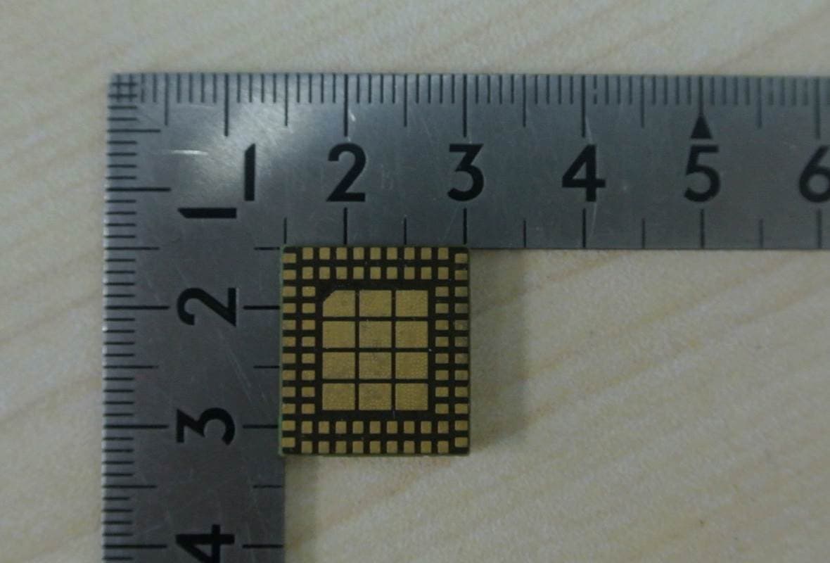
Click to zoom
Application Details
- Equipment Class
- PCB - PCS Licensed Transmitter
- Date of Grant
- Sep 08, 2013
- Application Purpose
- Original Equipment
- Date of Application
- Sep 04, 2013
- Equipment Note
- GSM/GPRS Wireless Data Module
- Frequency Range
- 1850.20000000 - 1909.80000000
- Company
- Shanghai Simcom Ltd.
- Country
- China
Documents & Files
Document Text
Text extracted from the exhibit documents filed with the FCC. Open a document above to read the original.
Users Manual
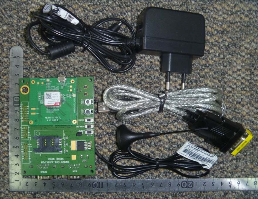
SIM800L-EVB_User Guide_V1.00 Smart Machine Smart Decision SIM800L-EVB_User Guide_V1.00 2 2013-07-22 Document Title: SIM800L-EVB_User Guide Version: 1.00 Date: 2013-07-22 Status: Release Document Control ID: SIM800L-EVB_User Guide_V1.00 General Notes Simcom offers this information as a service to its customers, to support application and engineering efforts that use the products designed by Simcom. The information provided is based upon requirements specifically provided to Simcom by the customers. Simcom has not undertaken any independent search for additional relevant information, including any information that may be in the customer’s possession. Furthermore, system validation of this product designed by Simcom within a larger electronic system remains the responsibility of the customer or the customer’s system integrator. All specifications supplied herein are subject to change. Copyright This document contains proprietary technical information which is the property of SIMCOM Limited., copying of this document and giving it to others and the using or communication of the contents thereof, are forbidden without express authority. Offenders are liable to the payment of damages. All rights reserved in the event of grant of a patent or the registration of a utility model or design. All specification supplied herein are subject to change without notice at any time. Copyright © Shanghai SIMCom Wireless Solutions Ltd. 2013 Smart Machine Smart Decision SIM800L-EVB_User Guide_V1.00 3 2013-07-22 Contents Contents ............................................................................................................................................ 3 Version History ................................................................................................................................. 4 1. SIM800L EVB .............................................................................................................................. 5 2. EVB Accessory ............................................................................................................................. 7 3. Accessory Interface ....................................................................................................................... 8 3.1 Power Interface ................................................................................................................... 8 3.2 Audio Interface .................................................................................................................... 8 3.3 SIM card interface ............................................................................................................... 9 3.4 RS232 Interface ................................................................................................................... 9 4. Illustration: .................................................................................................................................. 11 4.1 Running: ............................................................................................................................ 11 4.2 Connecting Net and calling ............................................................................................... 11 4.3 Downloading ..................................................................................................................... 11 4.4 Turns off ............................................................................................................................ 11 Figure Index FIGURE 1: EVB TOP VIEW ................................................................................................................... 5 FIGURE 2: EVB BOTTOM VIEW .......................................................................................................... 6 FIGURE 3: EVB ACCESSORY ............................................................................................................... 7 FIGURE 4: POWER INTERFACE .......................................................................................................... 8 FIGURE 5: AUDIO INTERFACE ........................................................................................................... 8 FIGURE 6: SIM CARD INTERFACE ..................................................................................................... 9 FIGURE 8: SERIAL PORTS .................................................................................................................... 9 Smart Machine Smart Decision SIM800L-EVB_User Guide_V1.00 4 2013-07-22 Version History Data Version Description of change Author 2013-07-22 1.00 Origin Lee Smart Machine Smart Decision SIM800L-EVB_User Guide_V1.00 5 2013-07-22 1. SIM800L EVB Figure 1: EVB TOP view A A B C D E M L J I H N F G O P K Smart Machine Smart Decision SIM800L-EVB_User Guide_V1.00 6 2013-07-22 Figure 2: EVB BOTTOM view A. SIM800L module B. Power key ( module ON/OFF control ) C. Reset key ( reset the module ) D. Power switch ( download control ) E. Charge switch ( charge ON/OFF control ) F. Headset interface G. USB H. SIM card interface I. Debug serial port J. MAIN serial port K. Test point interface L. GSM antenna interface M. Switch 1 N. Switch 2 O. Test point interface P. Test point interface Q. Headphones interface R. Source adapter interface Q R Smart Machine Smart Decision SIM800L-EVB_User Guide_V1.00 7 2013-07-22 2. EVB Accessory Figure 3: EVB accessory A: GSM antenna Model GSM antenna: WT-C&G-28-90 Frequency Range (MHz) 824 ~ 960 1710 ~ 1990 VSWR ≤1.5 (900MHz) ≤2 (1800MHz) Gain: 3dBi Input Impedance (Ω): 50 Polarization Type: Vertical Connector Type: SMA B: Antenna transmit line C: 5V DC source adapter D: Serial port line NOTE: The maximum gain of the GSM antenna gain should not exceed 3dBi for end-users. Smart Machine Smart Decision SIM800L-EVB_User Guide_V1.00 8 2013-07-22 3. Accessory Interface 3.1 Power Interface Figure 4: Power Interface Pin Signal I/O Description 1 Adapter input I 5V/2.5A DC source input 3…
Text truncated - open the document above for the full version.
Users Manual
SIM800L Document - 1 - SIM800L User Manual Compliance Information FCC Compliance Statement: This device complies with Part 15 of the FCC Rules . Operation is subject to the following two conditions: 1. This device may not cause harmful interference, and 2. This device must accept any interference received, including interference that may cause undesired operation. This device must accept any interference received, including interference that may cause undesired operation. Product that is a radio transmitter is labeled with FCC ID. FCC Caution: (1)Exposure to Radio Frequency Radiation. This equipment must be installed and operated in accordance with provided instructions and the antenna(s) used for this transmitter must be installed to provide a separation distance of at least 20 cm from all persons and must not be collocated or operating in conjunction with any other antenna or transmitter. End-users and installers must be provided with antenna installation instructions and transmitter operating conditions for satisfying RF exposure compliance. (2) Any changes or modifications not expressly approved by the grantee of this device could void the user's authority to operate the equipment. (3) This Transmitter must not be co-located or operating in conjunction with any other antenna or transmitter. (4) Changes or modifications to this unit not expressly approved by the party responsible for compliance could void the user authority to operate the equipment. (5) the modules FCC ID is not visible when installed in the host, or (6) if the host is marketed so that end users do not have straight forward commonly used methods for access to remove the module so that the FCC ID of the module is visible; then an additional permanent label referring to the enclosed module: Contains Transmitter Module FCC ID: UDV-2013072402 or Contains FCC ID: UDV-2013072402 must be used. 1. SIM800L Description 1.1. Summarize SIM800L designed by SIMCom is a quad band module which supports GSM/GPRS. The baseband circuit is based on MTK and RF circuit is based on RFMD. It works at quad bands------GSM850, EGSM900, DCS1800, and PCS1900. CPU clock is based on 26MHz crystal. The main IC includes MT6260S and RF7176. 1.2. Feature ● Quad-Band 850/900/1800/1900MHz ● GPRS multi-slot class 12/10 ● GPRS mobile station class B ● Compliant to GSM phase 2/2+ – Class 4 (2 W @ 850/900 MHz) – Class 1 (1 W @ 1800/1900MHz) SIM800L Document - 2 - ● Dimensions: 15.8*17.8*2.4 mm ● Weight: 1.25 g ● Control via AT commands (3GPP TS 27.007, 27.005 and SIMCom enhanced AT Commands) ● Supply voltage range 3.6~4.2 V ● Low power consumption ● Operation temperature:-30~80°C ● 88 LGA pads include – Interface to external SIM 3V/1.8V – Analog audio interface – RTC backup – Serial interface – USB interface – Keypad interface – LCD interface – Antenna pad – PCM – GPIO – ADC SIM800L Document - 3 - 1.3. Pin 1.4. Picture Figure 1: Top and Bottom view of SIM800L SIM800L Document - 4 - 1.5. Dimension Figure 2: Dimention SIM800L Document - 5 - 2. Detail Block Diagram Figure 3: Block diagram of SIM800L 3. Electrical and Reliability Characteristics 3.1. Absolute Maximum Ratings The absolute maximum ratings stated in following table are stress ratings under non-operating conditions. Stresses beyond any of these limits will cause permanent damage to SIM800L. Table 1: Absolute maximum ratings Symbol Parameter Min Ty p Max Unit VBAT Power supply voltage - - 4.5 V VBUS - - 30 V VBUS I I * Input current - - 8 mA I O * Output current - - 8 mA * These parameters are for digital interface pins, such as keypad, GPIO, I 2 C, UART, LCD and DEBUG. SIM800L Document - 6 - 3.2. Digital Interface Characteristics Table 2: Digital interface characteristics Symbol Parameter Min Ty p Max Unit I IH High-level input current 2.1 - 3.1 V I IL Low-level input current -0.3 - 0.7 V V OH High-level input voltage 2.4 - - V V OL Low-level input voltage - - 0.4 V * These parameters are for digital interface pins, such as keypad, GPIO, I 2 C, UART, LCD, PWMs and DEBUG. 3.3. SIM Card Interface Characteristics Table 3: SIM card interface characteristics Symbol Parameter Min Ty p Max Unit I IH High-level input current -1 - 1 uA I IL Low-level input current -1 - 1 uA V IH High-level input voltage 1.4 - - V 2.4 - - V V IL Low-level input voltage - - 0.27 V 0.4 V V OH High-level output voltage 1.62 - - V 2.7 - - V V OL Low-level output voltage - - 0.36 V - - 0.4 V 3.4. SIM_VDD Characteristics Table 4: SIM_VDD characteristics Symbol Parameter Min Ty p Max Unit V O Output voltage 2.70 2.80 2.90 V I O Output current - - 50 mA 3.5. VRTC Characteristics Table 5: VRTC characteristics SIM800L Document - 7 - Symbol Parameter Min Ty p Max Unit V RTC-IN VRTC input voltage 2.8 V I RTC-IN VRTC input current - 3 - uA V RTC-OUT VRTC output voltage - 2.8 - V I RTC-OUT VRTC output current - 2 mA 3.6. Current Consumption (VBAT = 3.8V) Table 6: Current consumption Symbol Parameter Conditions Va l u e Unit I VRTC VRTC current VBAT disconnects. Backup battery is 3 V 2 uA I VBAT VBAT current Power down mode 50 uA Sleep mode BS-PA-MFRMS=9 1.0 mA BS-PA-MFRMS=5 1.2 BS-PA-MFRMS=2 1.8 Idle mode GSM 850 19 mA EGSM 900 DCS 1800 PCS 1900 Voice call GSM 850 EGSM 900 PCL=5 250 mA PCL=12 110 PCL=19 76 DCS 1800 PCS 1900 PCL=0 168 PCL=7 89 PCL=15 76 Data mode GPRS(1Rx,1Tx) GSM 850 EGSM 900 PCL=5 240 mA PCL=12 110 PCL=19 83 DCS 1800 PCS 1900 PCL=0 170 mA PCL=7 95 PCL=15 80 Data mode GPRS(4Rx,1Tx) GSM 850 EGSM 900 PCL=5 270 mA PCL=12 150 PCL=19 120 DCS 1800 PCS 1900 PCL=0 205 mA PCL=7 130 PCL=15 115 Data mode GSM 850 PCL=5 440 mA SIM800L Document - 8 - GPRS(3Rx,2Tx) EGSM 900 PCL=12 185 PCL=19 130 DCS 1800 PCS 1900 PCL=0 300 mA PCL=7 155 PCL=15 122 I VBAT-peak Peak current During Tx burst 2 A 3.7. Electro-Static Discharge SIM800L is an ESD sensitive component, so more attention should be paid to the procedure of handling and packaging. The ESD test results are shown in the following table. Table 7: The ESD characteristics (Temperature: 25°…
Text truncated - open the document above for the full version.
Cover Letter(s)
Smart Machine Smart Decision Modular Approval Request Letter Aug. 26, 2013 Dear Application Examiner, Shanghai Simcom Ltd. 850/900/1800/1900 GSM/GPRS Modular, modular name:SIM800L, FCC ID: UDV-2013072402 would like to have your authorization as a modular approval. The requirements of Public Notice DA00-1407 have been met and shown on the following statements. Requirement of Public Notice DA00-1407 / part 15.212Answer from applicant 1. The modular transmitter must have its own RF shielding. Yes, The EUT does provide a RF shielding. Refer to EUT Picture. 2. The modular transmitter must have buffered modulation/data inputs (if such inputs are provided) to ensure that the module will comply with Part 15 requirements under conditions of excessive data rates or over-modulation. The EUT has buffered data input it’s integrated in chip MT6260S. 3. The modular transmitter must have its own power supply regulation. The EUT has its own power supply regulation it’s integrated in chip MT6260S. 4. The modular transmitter must comply with the antenna requirements of Section 15.203 and 15.204(c). The antenna must either be permanently attached or employ a “unique” antenna coupler (at all connections between the module and the antenna, including the cable).. No, The EUT does not meet the FCC antenna requirements, a standard of SMA antenna connector provide, refer to picture and antenna spec for the detail. 5. The modular transmitter must be tested in a stand-alone configuration, i.e., the module must not be inside another device during testing. This is intended to demonstrate that the module is capable of complying with Part 15 emission limits regardless of the device into which it is eventually installed. The EUT was tested in a stand- alone configuration via a test kit. Please see section photographs of test configuration in the test report. 6. The modular transmitter must be labeled with its own FCC ID number, and, if the FCC ID is not visible when the module is installed inside another device, then the outside of the device into which the module is installed must also display a label referring to the enclosed module. This exterior label can use wording such as the following: “Contains Transmitter Module FCC ID: XYZMODEL1” or “Contains FCC ID: XYZMODEL1.” Any similar wording that expresses the same meaning may be used. The Grantee may either provide such a label, an example of which must be included in the application for equipment authorization, or, must provide adequate instructions along with the module which explain this requirement. In the latter case, a copy of these instructions must be included in the application for equipment authorization. Please see exhibition label sample for the FCC ID of this module. And also in the exhibition User manual, there are instructions given to the OEM on how to label the end product. 7. The modular transmitter must comply with any specific rule or operating requirements applicable to the transmitter and the manufacturer must provide adequate instructions along with the module to explain any such requirements. A copy of these instructions must be included in the application for equipment authorization. For example, there are very strict operational and timing requirements that must be met before a transmitter is authorized for operation under Section 15.231. For instance, data transmission is prohibited, except for operation under Section 15.231(e), in which case there are separate field strength level and timing requirements. Compliance with these requirements must be assured. The EUT is compliant with all applicable FCC rules. Details instructions for maintaining compliance are give in the User Manual. Smart Machine Smart Decision 8. The modular transmitter must comply with any applicable RF exposure requirements. For example, FCC Rules in Sections 2.1091, 2.1093 and specific Sections of Part 15, including 15.319(i), 15.407(f), 15.253(f) and 15.255(g), require that Unlicensed PCS, UNII and millimeter wave devices perform routine environmental evaluation for RF Exposure to demonstrate compliance. In addition, spread spectrum transmitters operating under Section 15.247 are required to address RF Exposure compliance in accordance with Section 15.247(b)(4). Modular transmitters approved under other Sections of Part 15, when necessary, may also need to address certain RF Exposure concerns, typically by providing specific installation and operating instructions for users, installers and other interested parties to ensure compliance. The EUT is comply with RF exposure requirement MPE evaluation . The MPE report is addressed in the RF exposure exhibition. Best regards, Chen Xin Project Manager
External Photos
External Photos for SIM800L Top View Bottom View GSM ANT Location Top View with EVB Bottom View with EVB
ID Label/Location Info
SIM800L Document - 1 - UDV-2013072402 ID Label 16.1MM 14.1MM FCC ID:UDV-2013072402 FCC ID:UDV-2013072402
Internal Photos
Internal photos for SIM800L Top View Bottom View GSM ANT Location
RF Exposure Info
Report No. : UL15820130826FCC26-2 Page: 1 of 5 RF Exposure Evaluation Declaration Product Name : GSM/GPRS Wireless Data Module Model No. : SIM800L FCC ID: UDV-2013072402 Applicant : Shanghai Simcom Ltd. Address : Building A, SIM Technology Building, No.633, Jinzhong Road,Changning District, Shanghai P.R. China Date of Receipt : 29/08/2013 Issued Date : 29/08/2013~04/09/2013 Report No. : UL15820130826FCC26-2 Report Version : V1.0 The test results relate only to the samples tested. The test results shown in the test report are traceable to the national/international standard through the calibration of the equipment and evaluated measurement uncertainty herein. This report must not be used to claim product endorsement by TAF, CNAS or any agency of the Government. The test report shall not be reproduced except in full without the written approval of Unilab Corporation. Report No. : UL15820130826FCC26-2 Page: 2 of 5 RF Exposure Evaluation Declaration Issued Date : 04/09/2013 Report No. : UL15820130826FCC26-2 Product Name : GSM/GPRS Wireless Data Module Applicant : Shanghai Simcom Ltd. Address : Building A, SIM Technology Building, No.633, Jinzhong Road,Changning District, Shanghai P.R. China Manufacturer : Shanghai SIMCom Ltd. Address : Building A, SIM Technology Building, No.633, Jinzhong Road,Changning District, Shanghai P.R. China Model No. : SIM800L EUT Voltage MIN: 3.6V, NOR: 3.8V, MAX: 4.2V Brand Name : SIMCom Applicable Standard : FCC OET Bulletin 65 Supplement C (Edition 01-01) Test Result : Complied Performed Location : Unilab (Shanghai) Co.,Ltd. FCC 2.948 register number is 714465 No.1350, Lianxi Road, Pudong New District, Shangha, China TEL:+86-21-5027-5125/FAX:+86-21-5027-5126-876 Documented By : (Technical Engineer: Andy Wei) Reviewed By : (Senior Engineer: Forest Cao) Approved By : (Supervisor: Eva Wang) Report No. : UL15820130826FCC26-2 Page: 3 of 5 1. EUT Description Product Name: GSM/GPRS Wireless Data Module Model Name: SIM800L Hardware Version: V1.02 Software Version: SIM800 R13.08 RF Exposure Environment: Uncontrolled GSM/ GPRS Support Band: GSM850/PCS1900 Tx Frequency Range: GSM 850: 824.2MHz ~848.8MHz PCS 1900: 1850.2MHz ~1909.8MHz Rx Frequency Range: GSM 850: 869.2MHz ~893.8MHz PCS 1900: 1930.2MHz ~1989.8MHz Type of modulation: GMSK for GSM and GPRS Antenna Type: external Antenna Peak Gain: 3 dBi for GSM and PCS Component AC Adapter: Model Name: JHC-A01-1A0 Input: AC 100-240V 50/60Hz Output: DC 5V/1A Report No. : UL15820130826FCC26-2 Page: 4 of 5 2. RF Exposure Evaluation 2.1 Limits According to FCC 1.1310: The criteria listed in the following table shall be used to evaluate the environment impact of human exposure to radio frequency (RF) radiation as specified in 1.1307(b) LIMITS FOR MAXIMUM PERMISSIBLE EXPOSURE (MPE) Frequency Range(MHz) Electric Filed Strength (V/m) Magnetic Filed Strength (A/m) Power Density (mW/cm2) Average Time (Minutes) (A)Limits for Occupation/Control Exposures 300-1500 -- -- F/300 6 1500-100,000 -- -- 5 6 (B)Limits for General Occupation/UnControlled Exposures 300-1500 -- -- F/1500 6 1500-100,000 -- -- 1 30 F= Frequency in MHz Friis Formula Friis transmission formula: Pd = (Pout*G)/(4*Pi*R2) Where Pd = power density in mW/cm2 Pout = output power to antenna in mW G = gain of antenna in linear scale Pi = 3.1416 R = distance between observation point and center of the radiator in cm Pd id the limit of MPE, 1 mW/cm2 . If we know the maximum gain of the antenna and the total power input to the antenna, through the calculation, we will know the distance r where the MPE limit is reached. 2.2.Test Procedure Software provided by client enabled the EUT to transmit and receive data at lowest, middle and highest channel individually. The temperature and related humidity: 18°Cand 78% RH. Report No. : UL15820130826FCC26-2 Page: 5 of 5 2.3.Test Result of RF Exposure Evaluation This device is evaluated by mobile device with general population/uncontrolled exposure condition For this device, the calculation is using the most conservative values, and the results are as follows: Test Mode ERP (dBm) EIRP (dBm) Peak EIRP (mW) Average EIRP (mW) Calculated RF Exposure at d = 20cm (mW/cm2) MPE Limit (mW/cm2) GSM 850 30.52 32.67 1849.27 232.81 0.05 0.55 GSM 1900 / 26.78 476.43 59.98 0.01 1.00 GPRS 850 30.36 32.51 1782.38 224.39 0.04 0.55 GPRS 1900 / 26.18 414.95 52.24 0.01 1.00 Test Mode Antenna Gain (dBi) Maximum Output Power (dBm) Maximum Output Power (mW) Average EIRP (mW) Calculated RF Exposure at d = 20cm (mW/cm2) MPE Limit (mW/cm2) GSM 850 3 35 3162.28 794.33 0.16 0.55 GSM 1900 3 32 1584.89 398.11 0.08 1.00 GPRS 850 3 35 3162.28 198.58 0.04 0.55 GPRS 1900 3 32 1584.89 99.53 0.02 1.00 This device can pass RF exposure limit.
Test Report
FCC RF Test Report Product Name : GSM/GPRS Wireless Data Module Model No. : SIM800L FCC ID : UDV-2013072402 Applicant : Shanghai Simcom Ltd. Address : Building A,SIM Technology Building,No.633 Jinzhong Road,Changning District,Shanghai R.R.China Date of Receipt : 29/08/2013 Test Date : 29/08/2013~04/09/2013 Issued Date : 04/09/2013 Report No. : UL15820130826FCC26-1 Report Version : V1.0 The test results relate only to the samples tested. The test results shown in the test report are traceable to the national/international standard through the calibration of the equipment and evaluated measurement uncertainty herein. This report must not be used to claim product endorsement by TAF, CNAS or any agency of the Government. The test report shall not be reproduced except in full without the written approval of Unilab Corporation. Unilab(Shanghai) Co.,Ltd. Report No. : UL15820130826FCC26-1 Page 2 of 63 Test Report Certification Issued Date : 26/08/2013 Report No. : UL15820130826FCC26-1 Product Name : GSM/GPRS Wireless Data Module Applicant : Shanghai Simcom Ltd. Address : Building A,SIM Technology Building,No.633,Jinzhong Road, Changning District,Shanghai R.R.China Manufacturer : Shanghai Simcom Ltd. Address : Building A,SIM Technology Building,No.633,Jinzhong Road, Changning District,Shanghai R.R.China Model No. : SIM800L EUT Voltage : MIN: 3.6V, NOR: 3.8V, MAX: 4.2V Brand Name : SIMCom Applicable Standard : ANSI/TIA-603-D-2010 FCC CFR Title 47 Part 2 FCC CFR Title 47 Part 22 Subpart H FCC CFR Title 47 Part24 Subpart E Test Result : Complied Performed Location : Unilab (Shanghai) Co.,Ltd. FCC 2.948 register number is 714465 No.1350, Lianxi Road, Pudong New District, Shangha,China TEL:+86-21-5027-5125/FAX:+86-21-5027-5126-876 Documented By : (Technical Engineer: Andy Wei) Reviewed By : (Senior Engineer: Forest Cao) Approved By : (Supervisor: Eva Wang) Unilab(Shanghai) Co.,Ltd. Report No. : UL15820130826FCC26-1 Page 3 of 63 TABLE OF CONTENTS Description Page SUMMARY OF TEST RESULT ................................................................................................................. 5 1. General Information ............................................................................................................................. 6 1.1. EUT Description ......................................................................................................................... 6 1.2. Mode of Operation .................................................................................................................... 6 1.3. Tested System Details .............................................................................................................. 7 1.4. Configuration of Tested System ............................................................................................. 8 1.5. EUT Exercise Software ............................................................................................................. 8 1.6. Test Environment ....................................................................................................................... 8 2. Peak Output Power .............................................................................................................................. 9 2.1. Test Equipment .......................................................................................................................... 9 2.2. Test Setup ................................................................................................................................... 9 2.3. Limit ........................................................................................................................................... 10 2.4. Test Procedure ......................................................................................................................... 11 2.5. Uncertainty ............................................................................................................................... 11 2.6. Test Result ................................................................................................................................ 12 2.7. Test Photograph....................................................................................................................... 15 3. Modulation Characteristic ................................................................................................................. 17 3.1. Test Equipment ........................................................................................................................ 17 3.2. Test Setup ................................................................................................................................. 17 3.3. Limit ........................................................................................................................................... 17 3.4. Test Procedure ......................................................................................................................... 17 3.5. Uncertainty ............................................................................................................................... 18 3.6. Test Result ................................................................................................................................ 18 3.7. Test Photograph....................................................................................................................... 19 4. Occupied Bandwidth.......................................................................................................................... 20 4.1. Test Equipment ........................................................................................................................ 20 4.2. Test Setup ................................................................................................................................. 20 4.3. Limit ........................................................................…
Text truncated - open the document above for the full version.
Test Setup Photos
1 Test Setup Photos for SIM800L Description: ERP / Radiated Spurious Measurement(Below 1GHz) Test Setup Description: EIRP / Radiated Spurious Measurement (Above 1GHz) Test Setup 2 Conducted Power Measurement / Modulation Characteristic / Occupied Bandwidth/ Spurious Emission At Antenna Terminals/ Conducted Spurious Emission Measurement Test Setup Description: Frequency Stability Under Temperature & Voltage Variations Test Setup
Contact Information
Applicant
yongsheng Li(Deputy General Manager)
Technical Contact
Shanghai Simcom Ltd.Xing Chen
[email protected]86-021-32523300
SIM Technology Building,,No.633, Jinzhong Road · Shanghai · China
Test Firm
UniLab (Shanghai) Co., Ltd.Wang Rong
Technical Specifications
| # | Rule Parts | Frequency Range | Power Output | Emission | Tolerance |
|---|---|---|---|---|---|
| 2 | 24E | 1.85 GHz - 1.91 GHz | 904.00 mW | 276KGXW | 0.022 ppm |
Other Applications from Shanghai Simcom Ltd.
UDV-SIM800C
Mar 19, 2015GSM/GPRS Module
Equipment Class
PCB - PCS Licensed Transmitter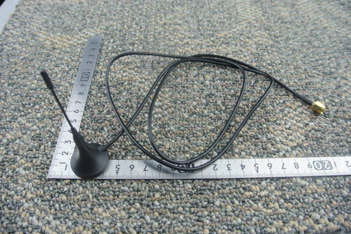
UDV-1403022014009
Sep 29, 2014WCDMA/HSDPA Module
Equipment Class
PCB - PCS Licensed Transmitter
UDV-1403022014008
Sep 29, 2014WCDMA/HSDPA Module
Equipment Class
PCB - PCS Licensed Transmitter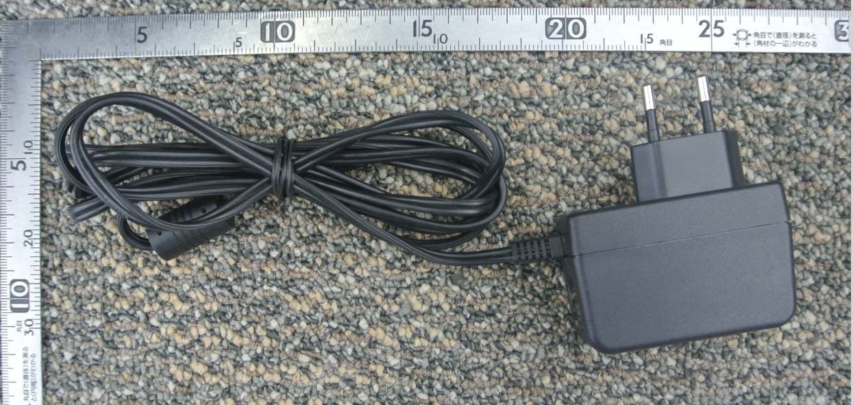
UDV-SIM5360A
Aug 07, 2014GSM/WCDMA Module
Equipment Class
PCB - PCS Licensed Transmitter
UDV-201314
Jan 22, 2014GSM/GPRS(850/900/1800/1900MHz)+BT Wireless Data Module
Equipment Class
DSS - Part 15 Spread Spectrum Transmitter