UFW-ALADDIN-NAGround Penetrating Radar
IDS GeoRadar s.r.l.
Click to zoom
Application Details
- Equipment Class
- UWB - Ultra Wideband Transmitter
- Date of Grant
- Jun 22, 2010
- Application Purpose
- Original Equipment
- Date of Application
- May 30, 2010
- Equipment Note
- Ground Penetrating Radar
- Frequency Range
- 630.00000000 - 2930.00000000
- Company
- IDS GeoRadar s.r.l.
- Country
- Italy
Documents & Files
Document Text
Text extracted from the exhibit documents filed with the FCC. Open a document above to read the original.
Users Manual
T ot pag. N°. = 32 - P RO/010/M1 Rev 3 - INGEGNERIA DEI SISTEMI S.p.A. Rev. 1.1 Protocol: MN/2009/061 “ALADDIN” STRUCTURE KIT USER MANUAL Pisa, 12/02/2010 “ALADDIN” STRUCTURE KIT User Manual IDS Ingegneria Dei Sist emi S.p.A. P rot ocol: MN/2009/061 - Rev. 1.1 “ALADDIN” STRUCTURE KIT User Manual 2 / 32 Document Evolution Revision Date Reason of chan ge Rev. 1.0 31/08/2009 First Edition Rev 1.1 12/02/2010 FCC Information up dated Versions covered by this document K2 All version, K2FastWave 02.00.008. OUR CONTACTS IDS Ingegneria dei Sistemi S .p.A. – GeoRadar Division Via Sterp ulino, 20 56121 Osp edaletto (PISA) - ITALIA Tel: +39.050.967111 Fax: +39.050.967121 inforis@ids-sp a.it Customer Care department: customercare. gp r@ids-sp a.it Tel.: +39.050.967122 S ales & Marketing department: sales.gp r@ids-sp a.it Tel.: +39.050.967123/24/43 IDS Ingegneria Dei Sist emi S.p.A. P rot ocol: MN/2009/061 - Rev. 1.1 “ALADDIN” STRUCTURE KIT User Manual 3 / 32 DISCLAIMER IDS WILL NOT BE HELD RESPONSIBLE FOR THE CONSEQUENCES OF AN IMPROPER USE OF THE EQUIPM ENT AND/OR THE SOFTWARE. THIS SOFTWARE MAY INCLUDE AUTOMATED DATA PROCESSING AND ANALYSIS TOOLS. WHILE EVER Y EFFORT IS M ADE TO ENSURE THE ACCURACY OF THE INFORMATION PROVIDED BY THOSE TOOLS, THEY M UST NOT BE INTENDED AS A SUBSTITUTE FOR INTELLIGENT ANALYSIS; RATHER, THEY HAVE TO BE INTENDED AS AN ADVISOR AND THE USER MUST NOT COM PLETELY RELY ON THE RESULTS PROVIDED BY THEM TO GIVE THE COM PLETE ANSWER. IDS INGEGNERIA DEI SISTEM I SPA ASSUM ES NO LIABILITY FOR ANY DIRECT, INDIRECT, SPECIAL, INCIDENTAL OR CONSEQUENTIAL DAMAGES OR INJURIES CAUSED BY SUCH RELIANCE ON THE ACCURACY, RELIABILITY, OR TIM ELESS OF THE INFORM ATION PROVIDED BY THOSE TOOLS. ANY PERSON OR ENTITY WHO RELIES ON INFORM ATION OBTAINED FROM THE AUTOMATED DATA PROCESSING/ANALYSI S TOOLS ONLY, DOES SO AT HIS OR HER OWN RISK IDS Ingegneria Dei Sist emi S.p.A. P rot ocol: MN/2009/061 - Rev. 1.1 “ALADDIN” STRUCTURE KIT User Manual 4 / 32 SAFETY INFORMATION The equipment conforms to the following requirements set by EC regulat ions, including subsequent modifications, and to the legis lat ion set by the member states that implement these regulations: 1999/05/EEC Radio Directive Warning: this equipment is destined for use in industrial environments (Class A apparatus). In residential, commercial and light industry environments, this apparatus may generate radio interference: in this case, the user may be required to operate while taking appropriate countermeasures. The apparatus is sensitive to the presence of external electromagnetic fields, which may reduce its performance. IDS Ingegneria Dei Sist emi S.p.A. P rot ocol: MN/2009/061 - Rev. 1.1 “ALADDIN” STRUCTURE KIT User Manual 5 / 32 SAFETY INFORMATION The equipment conforms to the following requirements set by EC regulat ions, including subsequent modifications, and to the legis lat ion set by the member states that implement these regulations: 1999/05/EEC Radio Directive Warning: this equipment is destined for use in industrial environments (Class A apparatus). In residential, commercial and light industry environments, this apparatus may generate radio interference: in this case, the user may be required to operate while taking appropriate countermeasures. The apparatus is sensitive to the presence of external electromagnetic fields, which may reduce its performance. IDS Ingegneria Dei Sist emi S.p.A. P rot ocol: MN/2009/061 - Rev. 1.1 “ALADDIN” STRUCTURE KIT User Manual 6 / 32 ! WARNING CLEANING INFORMATION Before cleaning any external parts of the apparatus, make sure that all cables have been disconnected, including the power supply cable. If a damp cloth is used, make sure it is not too wet, to avoid any damage to the electrical components of the equipment. Wait until the equipm ent is totally dry before reconnecting the cables. The system should be cleaned periodically using a damp cloth. Do not use solvents or abrasive detergents. Do not apply liquid directly to the electrical contacts of the various connectors. If a specific spray is used to clean the PC TFT monitor, make sure it is not flammable; ion any case, do not spray it directly on the screen, instead, spray it onto the cleaning cloth. IDS Ingegneria Dei Sist emi S.p.A. P rot ocol: MN/2009/061 - Rev. 1.1 “ALADDIN” STRUCTURE KIT User Manual 7 / 32 BATTERIES REMOVAL INFORMATION Laptop Batteries: Manufacturer: PANASONIC Type: Li-ion Ni Characteristics: 10.65V 5.7Ah Removal instructions: 1. turn off the laptop; 2. open the drawer with the symbol of the batteries; 3. extract the battery pack pulling the tab. Radar batteries: Manufacturer: FIAMM FG21202 / SAFT MP176065 Type: rechargeable lead acid / rechargeable lithium-ion Characteristics: 12V & 12Ah / 15V & 6.8Ah Removal instructions: 1. disconnect the battery from the instrument: a. pull the connector wings; b. separate the connectors; 2. remove the battery from the cover (optional) opening the strap. IDS Ingegneria Dei Sist emi S.p.A. P rot ocol: MN/2009/061 - Rev. 1.1 “ALADDIN” STRUCTURE KIT User Manual 8 / 32 RECICLYING The crossed out wheeled bin symbol shown on the equipment indicates that the product must be recycled separately from other waste at the end of its useful life. Separate waste disposal of this product at the end of its useful life will be organised and managed by IDS. When you decide to dispose of the equipment, contact IDS and follow the system that IDS has set up to permit the separate collection of the apparatus at its life end. Adequate separate collection for its subsequent recycling, treatment and environmental fr iendly disposal contribute towards avoiding any unnecessary effects on the environment and to health and favour the reuse or recycling of the materials that make up the equipment. Unauthorised disposal of this product as unsorted waste by its possessor will lead to an administrative penalty foreseen by national regulations. IDS Ingegneria Dei Sist emi S.p.A. P rot ocol: MN/2009/061 - R…
Text truncated - open the document above for the full version.
External Photos
EXTERNAL PICTURES “ Dead-man” swit ch on the ant enna, must be pushed at all t ime. When swit ch is released, pulse generat or will st op firing pulses wit hin 10 seconds.
External Photos
Digital Antenna Driver (D.A.D.) Unit: external picture Fig. 1: DAD external picture
ID Label/Location Info
1.5” 3” FCC ID: UFW-AL ADDIN-NA ED9GEMINIB This device comp lies with Part 15 of the FCC Rules. Op eration is subject to the followin g two conditions: (1) this device may not cause harmful interfer ence, and (2) this device must accep t any interference received, includin g interference that may cause undesired op eration.
Test Report
TT&T Laboratory Test Report No. ARSK00039 Date 2010-05-19 page 2 of 48 T ELECOMMUNICATIONS & T ELEMATICS FOR T RANSPORTS L ABORATORY CONTENTS 1 Introduction ................................................................................ 1-3 1.1 Scope ........................................................................................ 1-3 1.2 Test specifications, methods & procedures ............................... 1-3 2 General Description of Equipment under Test ........................ 2-4 2.1 Applicant .................................................................................... 2-4 2.2 Manufacturer ............................................................................. 2-4 2.3 Equipment classification ............................................................ 2-4 2.4 Basic description of equipment under test................................. 2-5 2.5 Feature of equipment under test ............................................... 2-5 3 Test Configuration of EUT......................................................... 3-6 3.1 EUT Operating test conditions................................................... 3-6 3.2 EUT Configurations ................................................................... 3-6 3.3 Description of support equipment .............................................. 3-6 4 General Test Set-Up ................................................................... 4-7 4.1 Environmental conditions........................................................... 4-7 4.2 Description................................................................................. 4-7 4.3 Drawings.................................................................................... 4-8 5 Summary Of Test Results.......................................................... 5-9 6 Measurements and Tests Data................................................ 6-10 7 Technical Documentation........................................................ 7-44 8 Photographic Documentation ................................................. 8-45 8.1 EUT Identification .................................................................... 8-45 8.2 Test set-up............................................................................... 8-46 9 Measurement Uncertainty ....................................................... 9-47 9.1 Radiated Emission Measurement Uncertainty from 30 to 1000 MHz9-47 9.2 Radiated Emission Measurement Uncertainty above 1000 MHz..... 9-47 10 List Of Measuring Equipment And Calibration Information 10-48 TT&T Laboratory Test Report No. ARSK00039 Date 2010-05-19 page 3 of 48 T ELECOMMUNICATIONS & T ELEMATICS FOR T RANSPORTS L ABORATORY 1 INTRODUCTION 1.1 Scope Obtain FCC Certification Authorization with the requirement of Title 47 of the Code of Federal Regulations Part 15 subpart F. 1.2 Test specifications, methods & procedures Publication Year Title 47 CFR Part 15 2008 Radio Frequency Device ANSI C63.4 2004 Methods of Measurement of Radio-Noise Emissions from Low-Voltage Electrical and Electronic Equipment in the Range of 9 kHz to 40 GHz FCC Order, ET Docket No. 98- 153 (FCC 02-48) 2002 Revision of Part 15 of the Commission’s Rules Regarding Ultra-Wideband Transmission Systems KDB Publication No. 393764 2007 UWB Compliance Measurements TT&T Laboratory Test Report No. ARSK00039 Date 2010-05-19 page 4 of 48 T ELECOMMUNICATIONS & T ELEMATICS FOR T RANSPORTS L ABORATORY 2 GENERAL DESCRIPTION OF EQUIPMENT UNDER TEST 2.1 Applicant NAME IDS INGEGNERIA DEI SISTEMI S.p.A. ADDRESS Via Livornese, 1019 – I-56122 PISA COUNTRY ITALY 2.2 Manufacturer NAME IDS INGEGNERIA DEI SISTEMI S.p.A. ADDRESS Via Sterpulino, 20 – I-56121 PISA COUNTRY ITALY 2.3 Equipment classification According to the definition 15.503 EUT is a Ground penetrating radar (GPR) system so it shall fulfil provisions of 47 CFR Part 15 Subpart F – Ultra Wideband Operation– Section 15.509. TT&T Laboratory Test Report No. ARSK00039 Date 2010-05-19 page 5 of 48 T ELECOMMUNICATIONS & T ELEMATICS FOR T RANSPORTS L ABORATORY 2.4 Basic description of equipment under test Parameters Value Type of equipment Ground penetrating radar (GPR) system Model ALADDIN NA FCC ID UFW-ALADDIN-NA Trade Name IDS INGEGNERIA DEI SISTEMI S.p.A. General Overview The ALADDIN NA system is a Ground penetrating radar (GPR) system, i.e., according to the FCC definition, a field disturbance sensor that is designed to operate only when in contact with the ground for the purpose of detecting or obtaining the images of buried objects or determining the physical properties within the ground. The energy from the GPR is intentionally directed down into the ground for this purpose. The EUT is a small device that may also be Hand Held without employ a fixed infrastructure. The System product includes • The ALADDIN bipolar antenna (including two couples of transmitting and receivingdipoles) • The control unit (hereinafter referred as D.A.D – Digital Antenna Driver) that is linked to a laptop computer for storing the collected data. 2.5 Feature of equipment under test Parameters Value Power supply type DC 12 V battery supplied Operating frequency 620,00 to 2930,00 MHz (10 dB Bandwidth) Channel Spacing Not applicable Pulse Repetition Frequency (PRF) 200 KHz Antenna description Integral permanently attached Antenna Type Dipole TT&T Laboratory Test Report No. ARSK00039 Date 2010-05-19 page 6 of 48 T ELECOMMUNICATIONS & T ELEMATICS FOR T RANSPORTS L ABORATORY 3 TEST CONFIGURATION OF EUT 3.1 EUT Operating test conditions Ref. Description #1 Continuous transmission with the antenna fitted in a manner typical of normal indented use. 3.2 EUT Configurations The Equipment under test was powered with a battery and placed directly on the dry sand with no ground plane under it. Hand Held with a support infrastructure 3.3 Description of support equipment Here following the details concerning equipment needed for correct operation or loading of the EUT: • None. TT&T Laboratory Test Report No. AR…
Text truncated - open the document above for the full version.
Contact Information
Applicant
Alessandro Simi(R & D Director)
Technical Contact
Istituto Italiano del Marchio di Qualita' S.p.A.Francesco Barbieri
[email protected]+39 02 5073
Via Quintiliano, 43 · Milan · Italy
Non-Technical Contact
Istituto Italiano del Marchio di Qualita' S.p.A.Fulvio Giorgi
[email protected]+39 02 5073
Test Firm
Istituto Italiano del Marchio di Qualita' S.p.A.Eng. Fulvio Giorgi
Technical Specifications
| # | Rule Parts | Frequency Range | Power Output |
|---|---|---|---|
| 1 | 15F | 630 MHz - 2.93 GHz | - |
Other Applications from IDS GeoRadar s.r.l.
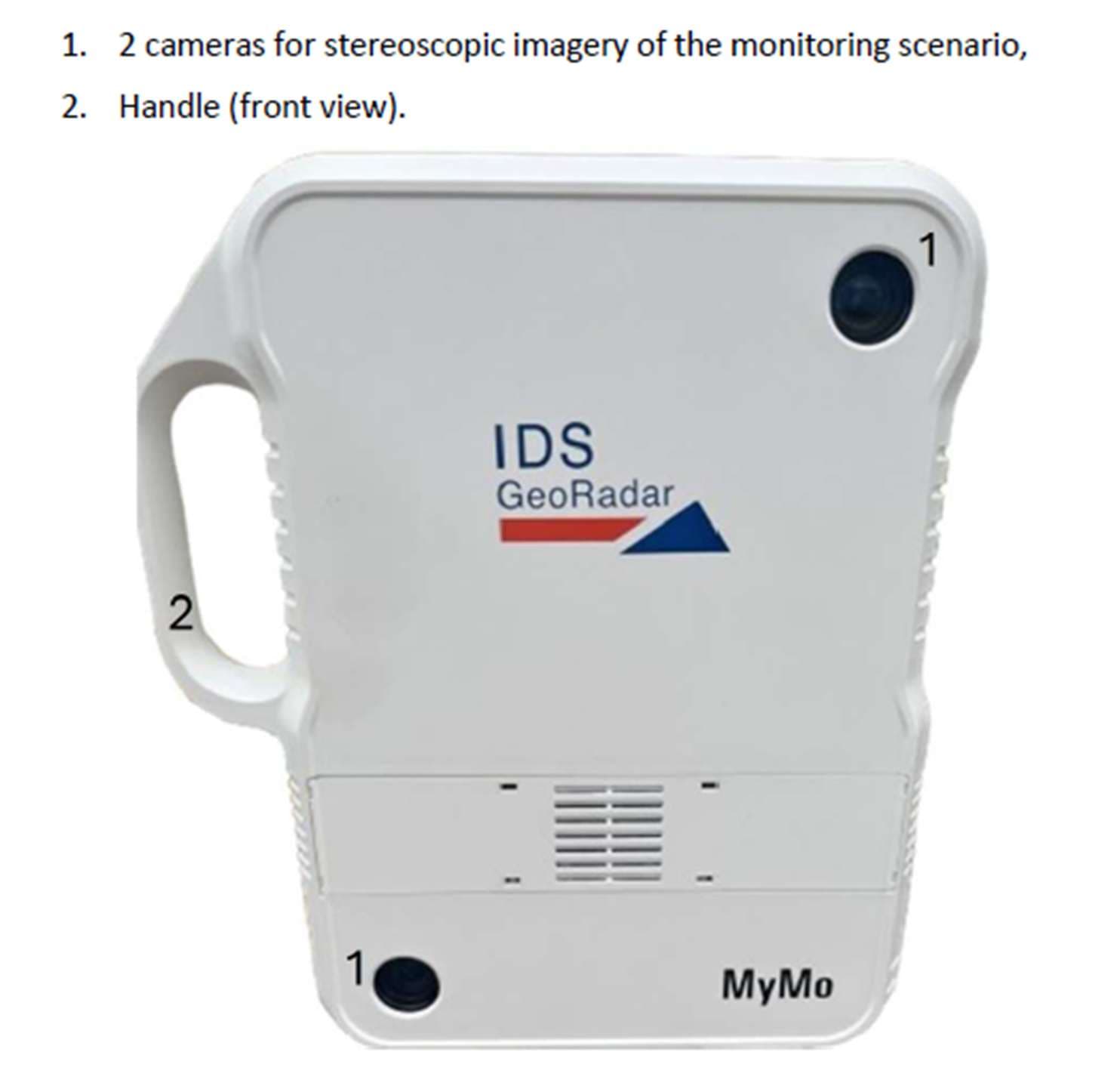
UFW-HYDRA2
Aug 11, 2026High Definition Ground Based SAR
Equipment Class
TNB - Licensed Non-Broadcast Station Transmitter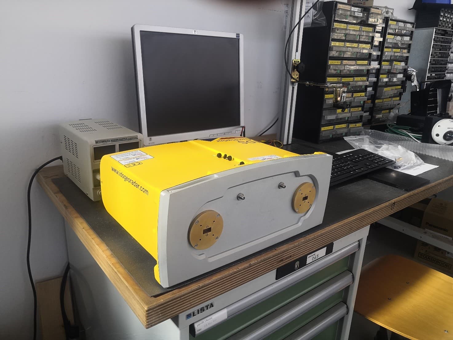
UFW-IBIS-KU-ETH3
Aug 05, 2024Ku-band radar sensor
Equipment Class
TNB - Licensed Non-Broadcast Station Transmitter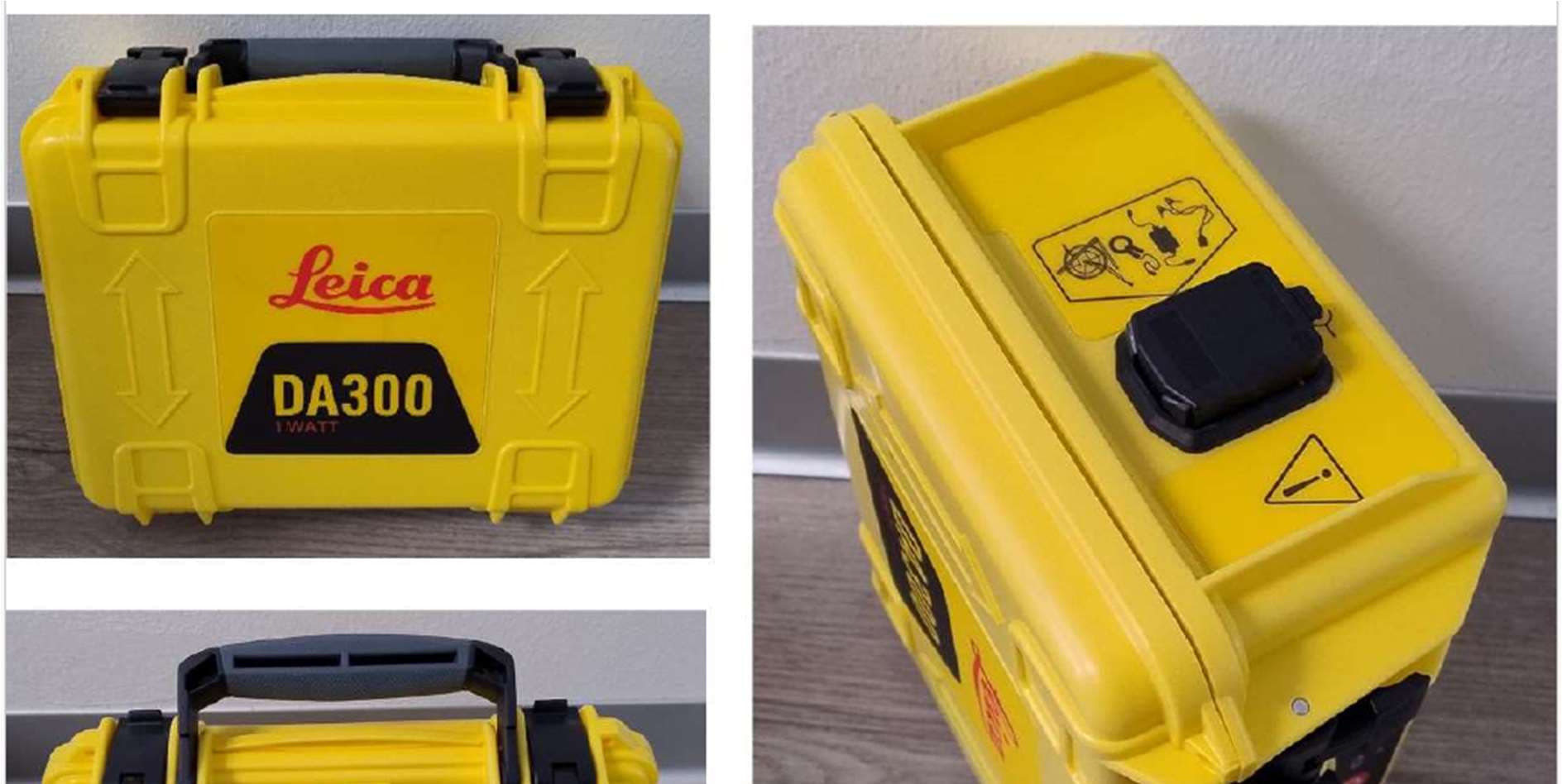
UFW-DA300
Jul 30, 2024Cable locator transmitter
Equipment Class
DCD - Part 15 Low Power Transmitter Below 1705 kHz
UFW-CHASERXR
Sep 25, 2023Chaser XR GPR CHASERXR
Equipment Class
UWB - Ultra Wideband TransmitterUFW-AM201
Jul 31, 2022GPR AM201
Equipment Class
UWB - Ultra Wideband Transmitter