UFW-HYDRA2High Definition Ground Based SAR
IDS GeoRadar s.r.l.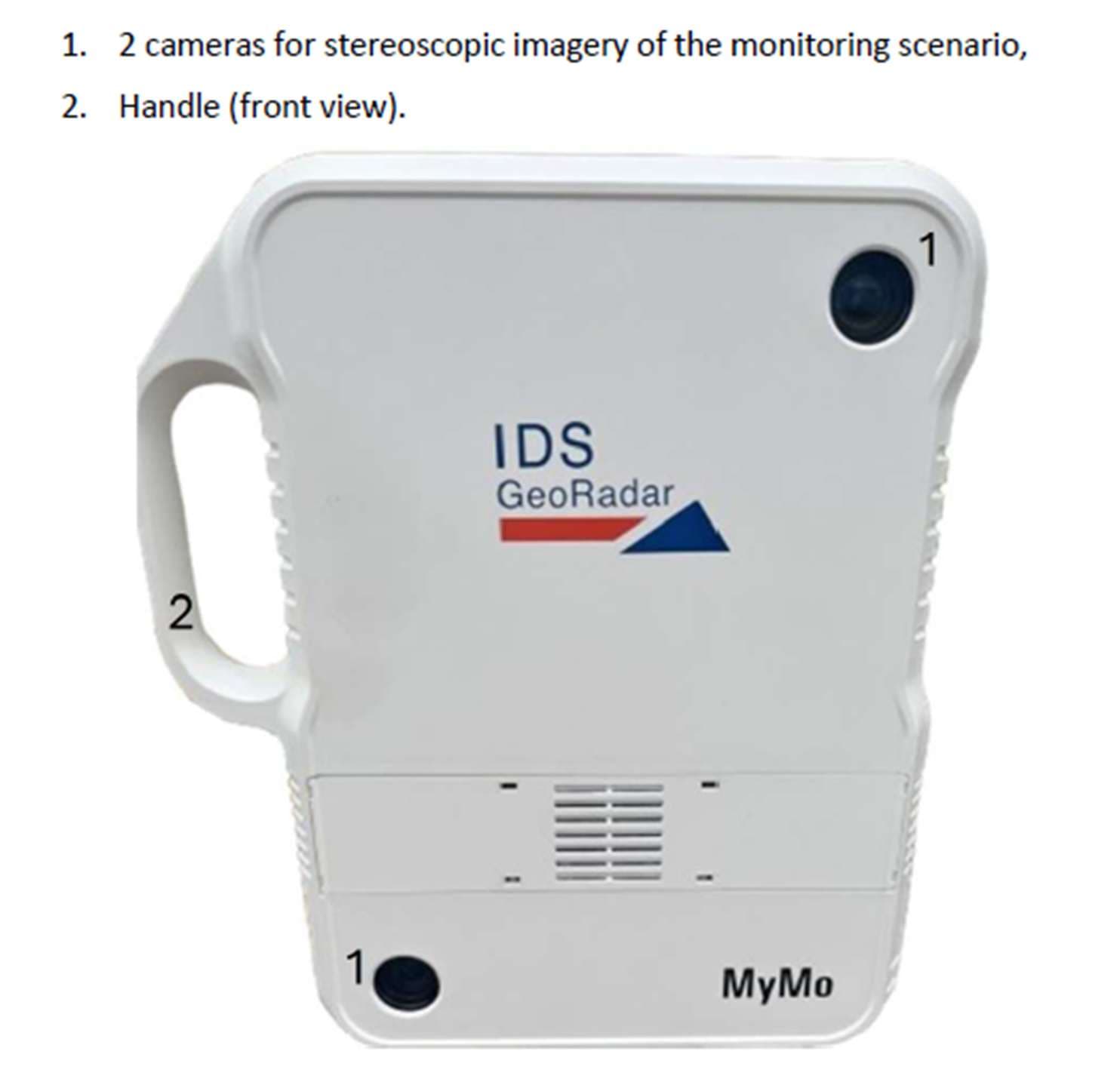
Click to zoom
Application Details
- Equipment Class
- TNB - Licensed Non-Broadcast Station Transmitter
- Date of Grant
- Aug 11, 2026
- Application Purpose
- Original Equipment
- Equipment Note
- High Definition Ground Based SAR
- Frequency Range
- 76000.00000000 - 77000.00000000
- Company
- IDS GeoRadar s.r.l.
- Country
- Italy
Documents & Files
Document Text
Text extracted from the exhibit documents filed with the FCC. Open a document above to read the original.
Users Manual
7 How to get started MyMo Field App Mod: MDM/011/M2 Rev 10 IDS GeoRadar Srl MNG/2025/012 Rev. 1.0 41/ 71 23. Re-insert the same 6-digit access code to confirm and press “continue” to proceed, 24. And the set-up procedure is complete, 25. The MyMo Field App Home page shall appear, and the system is ready to start monitoring. NOTICE: please, re-start MyMo at the end of the “unboxing” and before the first actual monitoring session. 7 How to get started MyMo Field App Mod: MDM/011/M2 Rev 10 IDS GeoRadar Srl MNG/2025/012 Rev. 1.0 42/ 71 7.2 How to get started MyMo Field App (using LAN cable connection) To get started MyMo Field App (in this case the PC Controller and MyMo are connected via LAN cable) follow the steps below: 1. Turn on MyMo using the O/I button, 2. Turn on the PC Controller, 3. Verify that the internal watch of the PC is synchronized, 4. Connect MyMo (use LAN 2 port of 5.4) and the PC Controller using the LAN cable (987232), 5. Press on the Network Connection icon and the connection is now established. 6. Follow now the same steps 9 to 25 as illustrated at 7.1 NOTICE: For MyMo to power on, hold the O/I button for about 6 seconds until the LEDs turns from white to green. After each start, MyMo perform a Buil-in-Test of the internal electronic. This operation takes about 3 minutes and after that the system is ready. Now, only battery and WiFi LEDs shall be on solid green. NOTICE: It is recommended to re-start MyMo at the end of the “unboxing” and before the first actual monitoring session. NOTICE: for connection stability, it is recommended to establish the LAN cable connection for the first start of the system. 8 HOW TO WORK ON SITE WITH MYMO Mod: MDM/011/M2 Rev 10 IDS GeoRadar Srl MNG/2025/012 Rev. 1.0 43/ 71 8. HOW TO WORK ON SITE WITH MYMO Steps described in Par. 7, are to be finalized only once, after unboxing the system, for the first time. To start any monitoring campaign instead, User should follow the steps below: 1. Install the system, based on field conditions and survey-specific requirements, following up instructions illustrated in paragraph 6, 2. Turn on MyMo (press the O/I button for about 6 seconds, until battery/power, WiFi, and Camera LED turn green), 3. Turn on the tablet/PC used with MyMo, 4. Connect MyMo and the tablet via WiFi or LAN cable, as illustrated in 7.1 or 7.2, respectively, 5. Launch MyMo Web App from your browser using the URL https://mymo.app.local/login 6. Enter your own access code, 7. And the page below shall appear indicating connection between MyMo and the PC. User and MyMo are now ready to start monitoring. The type of monitoring that MyMo can perform (Fig. 7) includes the following: 8 HOW TO WORK ON SITE WITH MYMO Mod: MDM/011/M2 Rev 10 IDS GeoRadar Srl MNG/2025/012 Rev. 1.0 44/ 71 1. Vibration and displacement analysis of structures (bridges, buildings...) in dynamic mode, at a distance up to 200 meters from MyMo sensor, and at a frequency up to 400Hz. The so-called Structure Health Monitoring (SHM). 2. Displacement analysis, of structures up to 400 meters away from the radar sensor, in Static mode (sampling time of 15 sec, 30 sec or 60 sec), and 3. Slope Monitoring, of natural or manmade slopes up to 400 meters from radar head sensor, in static mode. Fig. 7 Schematic view of MyMo monitoring types 8.1 How to...perform a Vibration and displacement analysis (dynamic mode) To monitor a structure in terms of its own displacement and resonant frequency, follow the steps below: 1. Create a new session by pressing icon in the window below, 2. If a session is still running a pop-up message shall appear, asking if the running session should be closed, 3. Enter the name of the new session and notes (if applicable), press continue, 8 HOW TO WORK ON SITE WITH MYMO Mod: MDM/011/M2 Rev 10 IDS GeoRadar Srl MNG/2025/012 Rev. 1.0 45/ 71 4. Select “Structure”, from the Type of Target icon, 5. Then, select “Vibration and displacement monitoring” from the monitoring session type icon, 6. Wait for the MyMo photogrammetric cameras to activate, 7. Verify if the survey area is fully included in the image, 8 HOW TO WORK ON SITE WITH MYMO Mod: MDM/011/M2 Rev 10 IDS GeoRadar Srl MNG/2025/012 Rev. 1.0 46/ 71 8. If not, adjust the heading of MyMo (refer to Fig. 4), until the survey area is included in the image on screen. 9. Take a photo of the monitoring area by pressing on the icon , and press “Continue”, 10. Select now the monitoring area, inside the photo just taken, by pressing with the mouse at each of the corners that should include the survey area, 11. Press DONE, when all the survey area is included (inside the blue dots, below), NOTICE: if possible, avoid including the sky within the monitoring area. 8 HOW TO WORK ON SITE WITH MYMO Mod: MDM/011/M2 Rev 10 IDS GeoRadar Srl MNG/2025/012 Rev. 1.0 47/ 71 12. A pop-up message indicating the maximum distance is now showing. NOTICE: For survey scenario located at a distance less than 30 meters, one single photo is enough. If the monitoring area is further away than this distance, more pictures (up to 6) should be taken by the Operator, after taking the radar head sensor from tripod, and following instructions of tablet screen. Pictures, should be taken moving sideways along the virtual base lines. 13. If the distance to target is more than 30 (e.g.: 100 meters in the image below), then MyMo field App will ask to take more photos, along a baseline of a given length (20 meters in the example below), 14. Take MyMo radar sensor off the tripod by holding with both hands, 15. Aim the MyMo Cameras towards the target to be monitored, 8 HOW TO WORK ON SITE WITH MYMO Mod: MDM/011/M2 Rev 10 IDS GeoRadar Srl MNG/2025/012 Rev. 1.0 48/ 71 16. Shortly press on the O/I button beside the icon to shoot a photo 17. Wait for the Camera LED to stop blinking , before taking the next photo, 18. The number of photos taken should appear on screen indicating how many photos of the scenario should still be taken, 19. Repeat the same until t…
Text truncated - open the document above for the full version.
Users Manual
IDS Geo MNG/2025/012 Rev. 1.0 June 2026 User Manual ORIGINAL INSTRUCTION IN ENGLISH LANGUAGE MyMo User Manual MyMo – Ver. 001 – User Manual Mod: MDM/011/M2 Rev11 IDS GeoRadar Srl MNG/2025/012 Rev. 1.0 2/ 71 LEGAL NOTICE Use of the Manual This Manual is intended to be used solely by authorized user of IDS GeoRadar Systems. It is specific for internal business purpose only. If you are not an authorized user, you are NOT allowed to read this Manual and you must return it to IDS GeoRadar as soon as possible. Access to and use of this Manual is also provided subject to the acceptance of the Disclaimer set out below. Disclaimer About the Manual This Manual has been drafted by IDS GeoRadar with the due care in order to ensure the accuracy and completeness. However, please note that no warranty is provided about the fact that the Manual will be free from error or omission and about the accuracy and/or fitness to the purpose of any information contained herein. Any representation and/or statement contained herein has been written in good faith and on the basis that, due to negligence, lack of care or otherwise, IDS GeoRadar is not liable for any loss, including direct, indirect or consequential losses, in contract or in tort for any misstatement or omission contained herein which has occurred or may occur with reference to any representation and/or statement contained in the Manual. User shall also acknowledge that some information contained in the Manual may not be up to date. IDS GeoRadar may amend the information contained in the Manual from time to time and IDS GeoRadar shall not be deemed liable in the event that damages arise with reference to changed circumstances or other information which may affect the accuracy of any information contained in this version of the Manual. About the Product All products designed, produced and distributed by IDS GeoRadar, its Subsidiaries, Affiliated and authorized Distributors (Products) shall not be used, in the design, development, production or use of chemical, biological, nuclear ballistic weapons. Buyer/ User will defend, indemnify and hold IDS GeoRadar harmless against any liability (including attorney’s fees) for non-compliance with the terms of this paragraph. If IDS GeoRadar requires that Buyer/User shall carry out a training with reference to some Product categories, no operation or use of the Products shall be started before its designated Operator/s has got the User Certificate, as defined by IDS GeoRadar specific procedure which the Buyer confirms to know and accept. For Products which include specific “Operational” software with automatic data processing and analysis “Tools”, e.g. RockSpot, IBIS Products; MyMo, User shall be aware that the results provided by these “Tools” may be not error free. User that completely relies on the outcomes provided by these Tools only, does it at his own risk. In no event IDS GeoRadar shall be liable for special, direct, indirect, incidental, exemplary, punitive or consequential damages including, but not limited to, loss of profits or revenue, caused by the missed or incomplete observance of the instructions and prescriptions for the use of the Products, either separately or in combination with other products. This paragraph provides only a non-exhaustive summary of the full Product disclaimer. Please see the full Product disclaimer included into the relevant section of this Manual for detailed information. Confidentiality This Manual may be subject to legal and other privilege. IDS GeoRadar specifically reserves its rights in relation to this Manual. None of these rights or any other rights subsisting in the Manual are waived if you have received this Manual in error or without permission. No parts of this Manual may be copied, translated or reduced to any electronic medium, or machine-readable form, nor photographed or recorded in any way, without the prior written consent of IDS GeoRadar. INDEX Mod: MDM/011/M2 Rev10 IDS GeoRadar Srl MNG/2025/012 Rev. 1.0 3/ 71 INDEX 1. INTRODUCTION .......................................................................................................................................................................................................................................... 6 1.1 ESTIMATED READING TIME .................................................................................................................................................................................................................................. 6 1.2 PURPOSE .......................................................................................................................................................................................................................................................... 6 1.3 APPLICATION FIELD ............................................................................................................................................................................................................................................. 6 1.4 INTENDED READERSHIP ........................................................................................................................................................................................................................................ 6 1.5 AUTHORIZATION OF USE ...................................................................................................................................................................................................................................... 6 1.5.1 CE Compliance ...................................................................................................................................................................................................................................... 6 1.5.2 Japan Compliance .....................................................................................................................................................…
Text truncated - open the document above for the full version.
Test Report
TEST REPORT Test report no.: 1-9686-25-02-02_TR3-R01 Testing laboratory Applicant cetecom advanced GmbH Untertuerkheimer Strasse 6 – 10 66117 Saarbruecken / Germany Phone: + 49 681 5 98 - 0 Fax: + 49 681 5 98 - 9075 Internet: https://www.cetecomadvanced.com e-mail: [email protected] Accredited Testing Laboratory: The testing laboratory (area of testing) is accredited according to DIN EN ISO/IEC 17025 (2018-03) by the Deutsche Akkreditierungsstelle GmbH (DAkkS). The accreditation is valid for the scope of testing procedures as stated in the accreditation certificate with the registration number: D-PL-12047-01-00. ISED Testing Laboratory Recognized Listing Number: DE0001 FCC designation number: DE0002 IDS GeoRadar s.r.l. Via Augusto Righi 6, 6A,8 56121 PISA (PI) / ITALY Phone: Contact: Marco Simoni e-mail: [email protected] Manufacturer IDS GeoRadar s.r.l. Via Augusto Righi 6, 6A,8 56121 PISA (PI) / ITALY Test standard/s FCC - Title 47 CFR Part 95 FCC - Title 47 of the Code of Federal Regulations; Chapter I; Part 95 - Personal Radio Services For further applied test standards please refer to section 3 of this test report. Test Item Kind of test item: Fixed Interferometric Radar System at 76-77 GHz Model name: HYDRA2 FCC ID: UFW-HYDRA2 Frequency band: 76.5 GHz band: 76 GHz – 77 GHz Technology tested: FMCW radar Antenna: Integrated antenna Power supply: 22.6 V to 26.4 V DC, by external power supply or battery Temperature range: -20°C to 55°C This test report is electronically signed and valid without handwritten signature. For verification of the electronic signatures, the public keys can be requested at the testing laboratory. Test report authorized: Test performed: Frank Heussner Stephan Thiel Coordinator Area Testing Manager Radio Labs Radio Labs Test report no.: 1-9686-25-02-02_TR3-R01 © cetecom advanced GmbH Page 2 of 49 1 Table of contents 1 Table of contents ....................................................................................................................................... 2 2 General information ................................................................................................................................... 3 2.1 Notes and disclaimer ...................................................................................................................... 3 2.2 Application details .......................................................................................................................... 3 2.3 Involved test locations .................................................................................................................... 4 2.4 Test laboratories sub-contracted .................................................................................................... 4 2.5 Laboratory listings and recognitions ............................................................................................... 4 3 Test standard/s, references and accreditations ......................................................................................... 5 4 Reporting statements of conformity – decision rule .................................................................................. 6 5 Test environment ...................................................................................................................................... 7 6 Test item ................................................................................................................................................... 7 6.1 General description ......................................................................................................................... 7 6.2 Additional information .................................................................................................................... 8 7 Description of the test setup ...................................................................................................................... 9 7.1 Shielded semi anechoic chamber .................................................................................................. 10 7.2 Shielded fully anechoic chamber ................................................................................................... 12 7.3 Radiated measurements > 18 GHz ................................................................................................ 14 7.4 Radiated measurements > 50/85 GHz ........................................................................................... 14 7.5 AC conducted ................................................................................................................................ 16 8 Sequence of testing ................................................................................................................................. 17 8.1 Sequence of testing radiated spurious 9 kHz to 30 MHz ............................................................... 17 8.2 Sequence of testing radiated spurious 30 MHz to 1 GHz ............................................................... 18 8.3 Sequence of testing radiated spurious 1 GHz to 18 GHz ............................................................... 19 8.4 Sequence of testing radiated spurious above 18 GHz.................................................................... 20 8.5 Sequence of testing radiated spurious above 50 GHz with external mixers ................................... 21 9 Measurement uncertainty ........................................................................................................................ 22 10 Summary of measurement results ....................................................................................................... 23 10.1 Summary ................................................................................................................................... 23 11 Additional comments .......................................................................................................…
Text truncated - open the document above for the full version.
Test Setup Photos
Annex A103 - Photographs No. 1-9686-25-02-02_TR1-A103-R02 November 28, 2025 DescriptionTest setup photos This document is electronically signed and valid without handwritten signature. Public keys for verifcation of the electronic signatures can be requested at the testing laboratory. Stephan Thiel Testing Manager Radio Labs authorized by cetecom advanced GmbH Untertuerkheimer Str. 6-10, 66117 Saarbruecken Document No. 1-9686-25-02-02_TR1-A103-R02 Page 1 of 7 Photo 1 EUT 1 Photo 2 EUT 1 cetecom advanced GmbH Untertuerkheimer Str. 6-10, 66117 Saarbruecken Document No. 1-9686-25-02-02_TR1-A103-R02 Page 2 of 7 Photo 3 EUT 1 Photo 4 EUT 1 cetecom advanced GmbH Untertuerkheimer Str. 6-10, 66117 Saarbruecken Document No. 1-9686-25-02-02_TR1-A103-R02 Page 3 of 7 Photo 5 EUT 1 Photo 6 EUT 1 cetecom advanced GmbH Untertuerkheimer Str. 6-10, 66117 Saarbruecken Document No. 1-9686-25-02-02_TR1-A103-R02 Page 4 of 7 Photo 7 EUT 1 Photo 8 EUT 1 cetecom advanced GmbH Untertuerkheimer Str. 6-10, 66117 Saarbruecken Document No. 1-9686-25-02-02_TR1-A103-R02 Page 5 of 7 Photo 9 EUT 1 Photo 10 EUT 1 cetecom advanced GmbH Untertuerkheimer Str. 6-10, 66117 Saarbruecken Document No. 1-9686-25-02-02_TR1-A103-R02 Page 6 of 7 Document History End of document ReleaseApplied changesRelease date R01initial releaseNovember 28, 2025 R02Setup foto for conducted emissions < 30MHzNovember 28, 2025 cetecom advanced GmbH Untertuerkheimer Str. 6-10, 66117 Saarbruecken Document No. 1-9686-25-02-02_TR1-A103-R02 Page 7 of 7
Test Report
Spurious emission at 3.7 GHz No.1-9686-25-02-02_TR1-A206-R01 November 27, 2025 Test Standard(s)NA - NI This document is electronically signed and valid without handwritten signature. Public keys for verification of the electronic signatures can be requested at the testing laboratory. Authorized Stephan Thiel Testing Manager Radio Labs cetecom advanced GmbH Untertürkheimer Str. 6-10, 66117 Saarbrücken Document No. 1-9686-25-02-02_TR1-A206-R01 Release 1 - Page 1 of 6 Table of Content NA # Hardcopy SA ~3 NA # Hardcopy SA ~5 cetecom advanced GmbH Untertürkheimer Str. 6-10, 66117 Saarbrücken Document No. 1-9686-25-02-02_TR1-A206-R01 Release 1 - Page 2 of 6 NA # Hardcopy SA ~ References TC start26.11.2025 18:33:21 Ambit temp (test rack) [°C] | humidity [rel%] 22.9 | 36 System version6.0.5.0 Standard | Version NA | NI Method DescriptionHardcopy spectrum analyzer InformationTID0019_1-9686-25-02-02_SER-Emission-3.7_GHz-Mode-1_Cycle- Time Equipment Signal analyzer,Rohde&Schwarz,FSW-26,1312.8000K26/101455,6.20 Test Parameter Technology to test READ SA SETTINGS: RefLevel [dBUV] | RefLevelOffset [dB] | InpAtt [dB]70.86 | 0.86 | 0 Start [MHz] | Stop [MHz]3733.349 | 3733.349 RBW [MHz] | VBW [MHz]1.000000 | 3.000000 Detector | TraceModeRMS | MAXH Sweep: time [ms] | count | points per Section | type600 | 0 | 6001 | SWE NA # Hardcopy SA ~ cetecom advanced GmbH Untertürkheimer Str. 6-10, 66117 Saarbrücken Document No. 1-9686-25-02-02_TR1-A206-R01 Release 1 - Page 3 of 6 RESULT DESCRIPTIONLOWER LIMITUPPER LIMITMEASUREDUNITVERDICT Marker Readout Marker 1 Time------0.000msINFO Marker 1 Mag.------46.94NIINFO RESULT DESCRIPTIONLOWER LIMITUPPER LIMITMEASUREDUNITVERDICT Delta Marker Readout Delta Marker 2 Time------50.100msINFO Delta Marker 2 Level------2.712dBINFO Delta Marker 3 Time------100.100msINFO Delta Marker 3 Level------4.417dBINFO Delta Marker 4 Time------150.200msINFO Delta Marker 4 Level------3.743dBINFO Verdict INFO cetecom advanced GmbH Untertürkheimer Str. 6-10, 66117 Saarbrücken Document No. 1-9686-25-02-02_TR1-A206-R01 Release 1 - Page 4 of 6 NA # Hardcopy SA ~ References TC start26.11.2025 18:39:23 Ambit temp (test rack) [°C] | humidity [rel%] 22.9 | 36 System version6.0.5.0 Standard | Version NA | NI Method DescriptionHardcopy spectrum analyzer InformationTID0020_1-9686-25-02-02_SER-Emission-3.7_GHz- Mode-1_Final_AV_lin Equipment Signal analyzer,Rohde&Schwarz,FSW-26,1312.8000K26/101455,6.20 Test Parameter Technology to test READ SA SETTINGS: RefLevel [dBUV] | RefLevelOffset [dB] | InpAtt [dB]70.86 | 0.86 | 0 Start [MHz] | Stop [MHz]3733.349 | 3733.349 RBW [MHz] | VBW [MHz]1.000000 | 3.000000 Detector | TraceModeAVER | MAXH Sweep: time [ms] | count | points per Section | type50000 | 0 | 1001 | SWE NA # Hardcopy SA ~ cetecom advanced GmbH Untertürkheimer Str. 6-10, 66117 Saarbrücken Document No. 1-9686-25-02-02_TR1-A206-R01 Release 1 - Page 5 of 6 RESULT DESCRIPTIONLOWER LIMITUPPER LIMITMEASUREDUNITVERDICT Marker Readout Marker 1 Time------15950.000msINFO Marker 1 Mag.------45.70NIINFO RESULT DESCRIPTIONLOWER LIMITUPPER LIMITMEASUREDUNITVERDICT Delta Marker Readout Verdict INFO - END OF DOCUMENT - cetecom advanced GmbH Untertürkheimer Str. 6-10, 66117 Saarbrücken Document No. 1-9686-25-02-02_TR1-A206-R01 Release 1 - Page 6 of 6
Test Report
Spurious emission at 2.5 GHz No.1-9686-25-02-02_TR1-A205-R01 November 27, 2025 Test Standard(s)NA - NI This document is electronically signed and valid without handwritten signature. Public keys for verification of the electronic signatures can be requested at the testing laboratory. Authorized Stephan Thiel Testing Manager Radio Labs cetecom advanced GmbH Untertürkheimer Str. 6-10, 66117 Saarbrücken Document No. 1-9686-25-02-02_TR1-A205-R01 Release 1 - Page 1 of 6 Table of Content NA # Hardcopy SA ~3 NA # Hardcopy SA ~5 cetecom advanced GmbH Untertürkheimer Str. 6-10, 66117 Saarbrücken Document No. 1-9686-25-02-02_TR1-A205-R01 Release 1 - Page 2 of 6 NA # Hardcopy SA ~ References TC start26.11.2025 18:49:52 Ambit temp (test rack) [°C] | humidity [rel%] 22.9 | 36 System version6.0.5.0 Standard | Version NA | NI Method DescriptionHardcopy spectrum analyzer InformationTID0022_1-9686-25-02-02_SER-Emission-2.5_GHz-Mode-1_Cycle- Time Equipment Signal analyzer,Rohde&Schwarz,FSW-26,1312.8000K26/101455,6.20 Test Parameter Technology to test READ SA SETTINGS: RefLevel [dBUV] | RefLevelOffset [dB] | InpAtt [dB]64.45 | -5.55 | 0 Start [MHz] | Stop [MHz]2533.062 | 2533.062 RBW [MHz] | VBW [MHz]1.000000 | 3.000000 Detector | TraceModeRMS | MAXH Sweep: time [ms] | count | points per Section | type500 | 0 | 5001 | SWE NA # Hardcopy SA ~ cetecom advanced GmbH Untertürkheimer Str. 6-10, 66117 Saarbrücken Document No. 1-9686-25-02-02_TR1-A205-R01 Release 1 - Page 3 of 6 RESULT DESCRIPTIONLOWER LIMITUPPER LIMITMEASUREDUNITVERDICT Marker Readout Marker 1 Time------0.000msINFO Marker 1 Mag.------49.19NIINFO RESULT DESCRIPTIONLOWER LIMITUPPER LIMITMEASUREDUNITVERDICT Delta Marker Readout Delta Marker 2 Time------50.900msINFO Delta Marker 2 Level------1.487dBINFO Delta Marker 3 Time------100.400msINFO Delta Marker 3 Level------5.025dBINFO Delta Marker 4 Time------150.600msINFO Delta Marker 4 Level------5.677dBINFO Verdict INFO cetecom advanced GmbH Untertürkheimer Str. 6-10, 66117 Saarbrücken Document No. 1-9686-25-02-02_TR1-A205-R01 Release 1 - Page 4 of 6 NA # Hardcopy SA ~ References TC start26.11.2025 18:53:46 Ambit temp (test rack) [°C] | humidity [rel%] 22.9 | 35 System version6.0.5.0 Standard | Version NA | NI Method DescriptionHardcopy spectrum analyzer InformationTID0023_1-9686-25-02-02_SER-Emission-2.5_GHz- Mode-1_Final_AV_lin Equipment Signal analyzer,Rohde&Schwarz,FSW-26,1312.8000K26/101455,6.20 Test Parameter Technology to test READ SA SETTINGS: RefLevel [dBUV] | RefLevelOffset [dB] | InpAtt [dB]64.45 | -5.55 | 0 Start [MHz] | Stop [MHz]2533.062 | 2533.062 RBW [MHz] | VBW [MHz]1.000000 | 3.000000 Detector | TraceModeAVER | MAXH Sweep: time [ms] | count | points per Section | type50000 | 0 | 1001 | SWE NA # Hardcopy SA ~ cetecom advanced GmbH Untertürkheimer Str. 6-10, 66117 Saarbrücken Document No. 1-9686-25-02-02_TR1-A205-R01 Release 1 - Page 5 of 6 RESULT DESCRIPTIONLOWER LIMITUPPER LIMITMEASUREDUNITVERDICT Marker Readout Marker 1 Time------27200.000msINFO Marker 1 Mag.------33.60NIINFO RESULT DESCRIPTIONLOWER LIMITUPPER LIMITMEASUREDUNITVERDICT Delta Marker Readout Verdict INFO - END OF DOCUMENT - cetecom advanced GmbH Untertürkheimer Str. 6-10, 66117 Saarbrücken Document No. 1-9686-25-02-02_TR1-A205-R01 Release 1 - Page 6 of 6
Test Report
Radiated test results for mode 3 No.1-9686-25-02-02_TR1-A203-R01 November 18, 2025 Test Standard(s)Systems FCC.ISED - NI This document is electronically signed and valid without handwritten signature. Public keys for verification of the electronic signatures can be requested at the testing laboratory. Authorized Stephan Thiel Testing Manager Radio Labs cetecom advanced GmbH Untertürkheimer Str. 6-10, 66117 Saarbrücken Document No. 1-9686-25-02-02_TR1-A203-R01 Release 1 - Page 1 of 9 Table of Content Systems FCC.ISED # Bandwidth 99pct ~ TID0010 MyMO 3 Systems FCC.ISED # Channel Power ~ TID0011 MyMO6 Systems FCC.ISED # Peak Power ~ TID0012 MyMO 8 cetecom advanced GmbH Untertürkheimer Str. 6-10, 66117 Saarbrücken Document No. 1-9686-25-02-02_TR1-A203-R01 Release 1 - Page 2 of 9 Systems FCC.ISED # Bandwidth 99pct ~ TID0010 MyMO References TC start18.11.2025 15:59:49 Ambit temp (test rack) [°C] | humidity [rel%] not enabled | not enabled System version6.0.5.0 Standard | Version Systems FCC.ISED | NI Method DescriptionSystems FCC ISED Bandwidth 99pct InformationIn-Band Config with 0 dB ATT Mode 3 Equipment Signal analyzer,Rohde&Schwarz,FSW-50,1331.5003K50/101332,6.20 Test Parameter EUT port1 Temperaturenom Voltagenom Auto control enabled power supply | Climatic Box No | No Full path type Full path name Switch bits READ SA SETTINGS: RefLevel [dBm] | RefLevelOffset [dB] | InpAtt [dB]30.00 | 56.2 | 40 Start [MHz] | Stop [MHz]75500.000 | 77500.000 RBW [MHz] | VBW [MHz]1.000000 | 3.000000 Detector | TraceModePOS | MAXH Sweep: time [ms] | count | points per Section | type100000 | 1 | 2001 | SWE cetecom advanced GmbH Untertürkheimer Str. 6-10, 66117 Saarbrücken Document No. 1-9686-25-02-02_TR1-A203-R01 Release 1 - Page 3 of 9 75600.0075800.0076000.0076200.0076400.0076600.0076800.0077000.0077200.0077400.00 MHz Frequency 30.0 25.0 20.0 15.0 10.0 5.0 0.0 -5.0 -10.0 -15.0 -20.0 -25.0 -30.0 dBm Magnitude BW 99pct Peak BW 99pct 75600.0075800.0076000.0076200.0076400.0076600.0076800.0077000.0077200.0077400.00 MHz Frequency 30.0 25.0 20.0 15.0 10.0 5.0 0.0 -5.0 -10.0 -15.0 -20.0 -25.0 -30.0 dBm Magnitude BW 99pct Peak Band BW 99pct within band RESULT DESCRIPTIONLOWER LIMITUPPER LIMITMEASUREDUNITVERDICT Bandwidth 99pct------196.59MHzINFO T1 99pct76000.00---76399.14MHzPASS cetecom advanced GmbH Untertürkheimer Str. 6-10, 66117 Saarbrücken Document No. 1-9686-25-02-02_TR1-A203-R01 Release 1 - Page 4 of 9 RESULT DESCRIPTIONLOWER LIMITUPPER LIMITMEASUREDUNITVERDICT T2 99pct---81000.0076595.72MHzPASS Max value @ 76400 MHz ------26.91dBmINFO Verdict PASS cetecom advanced GmbH Untertürkheimer Str. 6-10, 66117 Saarbrücken Document No. 1-9686-25-02-02_TR1-A203-R01 Release 1 - Page 5 of 9 Systems FCC.ISED # Channel Power ~ TID0011 MyMO References TC start18.11.2025 16:03:21 Ambit temp (test rack) [°C] | humidity [rel%] not enabled | not enabled System version6.0.5.0 Standard | Version Systems FCC.ISED | NI Method DescriptionSystems FCC ISED Channel power InformationIn-Band Config with 0 dB ATT Mode 3 Equipment Signal analyzer,Rohde&Schwarz,FSW-50,1331.5003K50/101332,6.20 Test Parameter EUT port1 Temperaturenom Voltagenom Auto control enabled power supply | Climatic Box No | No Full path type Full path name Switch bits READ SA SETTINGS: RefLevel [dBm] | RefLevelOffset [dB] | InpAtt [dB]10.00 | 56.2 | 40 Start [MHz] | Stop [MHz]75500.000 | 77500.000 RBW [MHz] | VBW [MHz]1.000000 | 3.000000 Detector | TraceModeRMS | MAXH Sweep: time [ms] | count | points per Section | type100000 | 1 | 2001 | SWE cetecom advanced GmbH Untertürkheimer Str. 6-10, 66117 Saarbrücken Document No. 1-9686-25-02-02_TR1-A203-R01 Release 1 - Page 6 of 9 75600.0075800.0076000.0076200.0076400.0076600.0076800.0077000.0077200.0077400.00 MHz Frequency 10.0 5.0 0.0 -5.0 -10.0 -15.0 -20.0 -25.0 -30.0 -35.0 -40.0 dBm Magnitude Band power RESULT DESCRIPTIONLOWER LIMITUPPER LIMITMEASUREDUNITVERDICT Channel power span-----…
Text truncated - open the document above for the full version.
Contact Information
Applicant
Alessandro Simi(R & D Director)
[email protected]Fax: 00390508934258
Technical Contact
Leica Geosystems Inc.Henry Munoz
5051 Peachtree Corners Cicle, Suite 250 · Norcross, 30092 · United States
Test Firm
cetecom advanced GmbHGerald Schmidt
[email protected]Fax: 49-681-598-8775
Technical Specifications
| # | Rule Parts | Frequency Range | Power Output | Emission | Tolerance |
|---|---|---|---|---|---|
| 1 | 9 | 76.00 GHz - 77.00 GHz | 210.00 mW | 779MF3N | 0.11% |
| 2 | 9 | 76.00 GHz - 77.00 GHz | 210.00 mW | 392MF3N | 0.11% |
| 3 | 9 | 76.00 GHz - 77.00 GHz | 210.00 mW | 196MF3N | 0.11% |
Other Applications from IDS GeoRadar s.r.l.
UFW-IBIS-KU-ETH3
Aug 05, 2024Ku-band radar sensor
Equipment Class
TNB - Licensed Non-Broadcast Station Transmitter
UFW-DA300
Jul 30, 2024Cable locator transmitter
Equipment Class
DCD - Part 15 Low Power Transmitter Below 1705 kHz
UFW-CHASERXR
Sep 25, 2023Chaser XR GPR CHASERXR
Equipment Class
UWB - Ultra Wideband TransmitterUFW-AM201
Jul 31, 2022GPR AM201
Equipment Class
UWB - Ultra Wideband Transmitter
UFW-ROCKSPOT
Oct 12, 2020X-band Interferometric Doppler Radar
Equipment Class
TNB - Licensed Non-Broadcast Station Transmitter