UFW-IBIS-KUIBIS Sensor Unit
IDS GeoRadar s.r.l.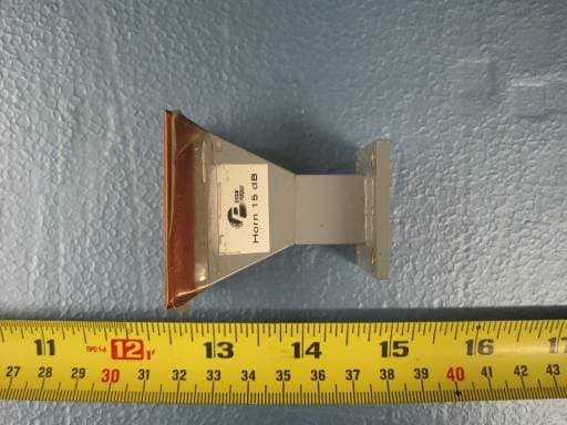
Click to zoom
Application Details
- Equipment Class
- TNB - Licensed Non-Broadcast Station Transmitter
- Date of Grant
- Jun 21, 2010
- Application Purpose
- Original Equipment
- Date of Application
- Jun 21, 2010
- Equipment Note
- IBIS Sensor Unit
- Frequency Range
- 17100.00000000 - 17300.00000000
- Company
- IDS GeoRadar s.r.l.
- Country
- Italy
Documents & Files
Document Text
Text extracted from the exhibit documents filed with the FCC. Open a document above to read the original.
Users Manual
Tot. N° pages = 48 - PRO/010/M1 Rev 4 - INGEGNERIA DEI SISTEMI S.p.A. R ev. 1.1 N°doc: MN/2009/071 Config.: IBIS-S-PRCS-OUT-MN IBIS-S System IMAGE BY INTERFEROMETRIC SURVEY Pisa, June 2010 IBIS-S v. 1.0 - User Manual IDS Ingegneria Dei Sistemi S.p.A. N doc: MN/2009/071 - Rev. 1.1 IBIS-S v. 1.0 - User Manual 2 / 48 A ll information contained in this document is property of IDS. All rights reserved. K EY WORDS IBIS-S, INTERFEROMETER, INSTALLATION SUMMARY IBIS-S system user manual. This document illustrates the contents of the package and the procedures the operator must perform to set up and dismantle the IBIS-S system. Document Evolution Revision Date Reason for change Rev. 1.0 October 2009 First Edition with Battery information (according to DL 188 dated 20/11/2008) Rev. 1.1 June 2010 Document revision for declarations for US and Canada (see RNC 201005097) Document change record RNC References Change description 201005097 Before index Declarations for US and Canadian customers HW and SW versions covered by this document IBIS-S apparatus v. 1.0. Warnings IDS will not be held responsible for the consequences of an improper use of the equipment. IDS will not be held responsible for the consequences of an improper use of the software All information contained in this document is property of IDS. IDS Ingegneria Dei Sistemi S.p.A. N doc: MN/2009/071 - Rev. 1.1 IBIS-S v. 1.0 - User Manual 3 / 48 A ll information contained in this document is property of IDS. All rights reserved. C ontacts IDS Ingegneria Dei Sistemi S.p.A. Via Sterpulino, 20 56121 PISA (Loc. Ospedaletto) Tel: +3905096711 Fax: +39050961721 IDS Ingegneria Dei Sistemi S.p.A. N doc: MN/2009/071 - Rev. 1.1 IBIS-S v. 1.0 - User Manual 4 / 48 A ll information contained in this document is property of IDS. All rights reserved. D ISCLAIMER IDS WILL NOT BE HELD RESPONSIBLE F OR THE CONSEQUENCES OF AN IMPROPER USE OF THE EQUIPMENT AND/ OR THE SOFTWARE. THIS SOFTWARE MAY INCLUDE AUTOMATED DATA PROCESSING AND ANALYSIS TOOLS. WHILE EVERY EFFORT IS MADE TO ENSURE THE ACCURACY OF THE INFORMATION PROVIDED BY THOS E TOOLS, THEY MUST NOT BE INTENDED AS A SUBSTITUTE FOR INTE LLIGENT ANALYSIS; RATHER, THEY HAVE TO BE INTEND ED AS AN ADVISOR AND THE USER MUST NOT COMPLETELY RELY ON THE RESULTS PROVIDED BY THEM TO GIVE THE COM PLETE ANSWER. IDS INGEGNERIA DEI SISTEMI SPA AS SUMES NO LIABILITY FOR ANY DIRECT, INDIRECT, SPECIAL, INCIDENTAL OR CONSEQUENTIAL DAMAGES OR INJURIES CAUSED BY SUCH RELIANCE ON THE ACCURACY, RELIABILITY, OR TIMELESS OF THE INFORMATION PROVIDED BY THOSE TOOLS. ANY PERSON OR ENTITY WHO RELIES ON INFORMATI ON OBTAINED FROM THE AUTOMATED DATA PROCESSING/ANALYSIS TOOLS ONLY , DOES SO AT HIS OR HER OWN RISK. IDS Ingegneria Dei Sistemi S.p.A. N doc: MN/2009/071 - Rev. 1.1 IBIS-S v. 1.0 - User Manual 5 / 48 A ll information contained in this document is property of IDS. All rights reserved. S AFETY INFORMATION IDS Ingegneria Dei Sistemi S.p.A. N doc: MN/2009/071 - Rev. 1.1 IBIS-S v. 1.0 - User Manual 6 / 48 A ll information contained in this document is property of IDS. All rights reserved. Warning: this equipment is destined for use in industrial environments (Class A apparatus). In residential, commercial and light industry environments, this apparatus may generate radio interference: in this case, the user may be required to operate while taking appropriate countermeasures. The apparatus is sensitive to the presence of external electromagnetic fields, which may reduce its performance. IDS Ingegneria Dei Sistemi S.p.A. N doc: MN/2009/071 - Rev. 1.1 IBIS-S v. 1.0 - User Manual 7 / 48 A ll information contained in this document is property of IDS. All rights reserved. I MPORTANT NOTE FOR THE US CUSTOMERS Model No.: IBIS-KU FCC ID: UFW-IBIS-KU This device complies with part 90 of the FCC Rules. Caution: Any changes or modifications to this device not explicitly approved by manufacturer could void your authority to operate this equipment. This equipment complies with FCC radiation exposure limits set forth for an uncontrolled environment. This equipment should be installed and operated with minimum 20 cm between the radiator and your body. This transmitter must not be collocated or operating in conjunction with any other antenna or transmitter unless authorized to do so by the FCC. IMPORTANT NOTE FOR THE CANADIAN CUSTOMERS Model No.: IBIS-KU IC ID: 8991A-IBISKU This device has been designed to operate with the antennas listed below, and having a maximum gain of 22 dB. Antennas not included in this list or having a gain greater than 22 dB are strictly prohibited for use with this device. The required antenna impedance is 50 ohms. IBIS-ANT1-H38V18 IBIS-ANT2-H29V25 IBIS-ANT3-H17V15 IBIS-ANT4-H11V10 IBIS-ANT5-H12V39 IBIS-ANT6-H51V20 Operation is subject to the following two conditions: (1) this device may not cause interference, and (2) this device must accept any interference, including interference that may cause undesired operation of the device. To reduce potential radio interference to other users, the antenna type and its gain should be so chosen that the equivalent isotropically radiated power (e.i.r.p.) is not more than that permitted for successful communication. IDS Ingegneria Dei Sistemi S.p.A. N doc: MN/2009/071 - Rev. 1.1 IBIS-S v. 1.0 - User Manual 8 / 48 A ll information contained in this document is property of IDS. All rights reserved. ! WARNING CLEANING INFORMATION Before cleaning any external parts of the apparatus, make sure that all cables have been disconnected, including the power supply cable. If a damp cloth is used, make sure it is not too wet, to avoid any damage to the electrical components of the equipment. Wait until the equipment is totally dry before reconnecting the cables. The IBIS-S should be cleaned periodically using a damp cloth. Do not use solvents or abrasive detergents. Do not apply liquid directly to the electrical contacts of the various connectors. If a specific spray is used to clean the PC TFT mon…
Text truncated - open the document above for the full version.
Cover Letter(s)
INGEGNERIA DEI SISTEMI S.p.A. PISA Branch Office Via Sterpulino, 20 - 56121 PISA (Italy) Tel. +39.050.9671.11 - Fax +39.050.9671.21 e-mail: [email protected] www.idscompany.it PISA Headquarters Via Livornese, 1019 56122 PISA (Italy) Tel. +39.050.3124.1 Fax +39.050.3124.201 e-mail: [email protected] PISA Branch Office Via Sterpulino, 20 56121 PISA (Italy) Tel. +39.050.9671.11 Fax +39.050.9671.21 e-mail: [email protected] ROMA Branch Office Via Flaminia, 1068 00189 ROMA (Italy) Tel. +39.06.33217.11 Fax +39.06.33217.402 e-mail: [email protected] Capitale Sociale 5.000.000 Euro i.v. – C.C.I.A.A. Pisa, R.E.A. n° 77042 - C.F. 00672210507 – P. IVA (VAT) IT 00672210507 Share Capital 5.000.000 euro fully paid – registered at the Pisa Chamber of Commerce, R.E.A. n. 77042 – Tax number and VAT code (IT) 00672210507 02/06/2010 To: SIEMIC, INC. 2206 Ringwood Avenue, San Jose, CA 95131 USA Dear Sir/Madam, Re: Project and Product Certification Representative Authorization Letter We, _______Ingegneria dei Sistemi S.p.A._________hereby authorize SIEMIC, INC. to act as a Certification Body for certifying for the following project(s): IBIS sensor IBIS Supply Unit IBIS Linear scanner We affirm that between SIEMIC and __ Ingegneria dei Sistemi S.p.A ___, any difference in understanding, including test plan, measurement methods, applicable standards and relevant procedures and processes have been resolved prior to commencement of testing activities. Sincerely, Guido Manacorda, Engineering Manager Via Sterpulino 20, 56100 Pisa Italy
Cover Letter(s)
INGEGNERIA DEI SISTEMI S.p.A. PISA Branch Office Via Sterpulino, 20 - 56121 PISA (Italy) Tel. +39.050.9671.11 - Fax +39.050.9671.21 e-mail: [email protected] www.idscompany.it PISA Headquarters Via Livornese, 1019 56122 PISA (Italy) Tel. +39.050.3124.1 Fax +39.050.3124.201 e-mail: [email protected] PISA Branch Office Via Sterpulino, 20 56121 PISA (Italy) Tel. +39.050.9671.11 Fax +39.050.9671.21 e-mail: [email protected] ROMA Branch Office Via Flaminia, 1068 00189 ROMA (Italy) Tel. +39.06.33217.11 Fax +39.06.33217.402 e-mail: [email protected] Capitale Sociale 5.000.000 Euro i.v. – C.C.I.A.A. Pisa, R.E.A. n° 77042 - C.F. 00672210507 – P. IVA (VAT) IT 00672210507 Share Capital 5.000.000 euro fully paid – registered at the Pisa Chamber of Commerce, R.E.A. n. 77042 – Tax number and VAT code (IT) 00672210507 02/06/2010 To: Federal Communications Commission Authorization and Evaluation Division 7435 Oakland Mills Road Columbia, MD Subject: Permanent Confidentiality Request for FCC ID: UFW-IBIS-KU We hereby request confidential treatment of information accompanying this application as outlined below: - Schematics - Block Diagram - Operational description - Part List - Tune up procedure The above materials contain trade secrets and proprietary information not customarily released to the public. The public disclosure of these materials may be harmful to the applicant and provide unjustified benefits to its competitors, especially for what concerns the internal pictures that would disclose to IDS’s competitors the technology adopted. More specifically the market for slope stability monitoring system and in general for landslide monitoring system is subject to significant competition, therefore IDS would be harmfully impacted by disclosure of such information and would suffer substantial harm to its competitive position with respect its monitoring system. The information in the Confidential Documents is not currently available to the public in any substantial similar form. IDS takes care to prevent this information from being disclosed to the public. The applicant understands that pursuant to Section 0.457 & 0.459 of the Rules, disclosure of this application and all accompanying documentation will not be made before the date of the Grant for this application. Sincerely, Guido Manacorda, Engineering Manager Via Sterpulino 20, 56122 Pisa Italy INGEGNERIA DEI SISTEMI S.p.A. 02/06/2010 To: Federal Communications Commission Office of Engineering and Technology Equipment Authorization Division 7345 Oakland Mills Road Columbia, Maryland 21046 Subject: Short Term Confidentiality Request for FCC ID: UFW-IBIS-KU To Whom It May Concern: Pursuant to sections 0.457 and 0.459 of CFR 47 and to avoid premature release of sensitive information prior to marketing or release of the product to the public, the applicant requests the following documents contained in this certification application be temporarily withheld from public disclosure for an initial period of 180 days: - User Manual - Internal pictures - External And setup Photo The above materials contain trade secrets and proprietary information not customarily released to the public. The public disclosure of these materials may be harmful to the applicant and provide unjustified benefits to its competitors. Sincerely, Sincerely, Client’s signature : Client’s name / title :Guido Manacorda, Engineering Manager Contact information / address : email: [email protected] Via Sterpulino 20, 56100 Pisa Italy
Cover Letter(s)
2206 Ringwood Avenue, San Jose, CA 95131, USA Tel: +1(408) 526 1188, Fax: +1(408) 526 1088, Email: [email protected], URL: www.siemic.com June 23, 2009 To: FCC From: SIEMIC, INC. RE: Applicant: Ingegneria dei Sistemi S.p.A, FCC ID: UFW-IBIS-KU, Request for supercede of test report exhibits Per customer’s request, There is some inappropriate information of EUT in the test report exhibits. These are very important information to customer for marketing purpose, therefore, we are asking to kindly replace the test report with revised copies. Thank you, Annie Jiang SIEMIC, INC. 2206 Ringwood Ave., San Jose, CA 95131 Tel: 408-526-1188 Ext 209 Fax: 408-526-1088
External Photos
MODEL: IBIS Sensor Ku Band EUT - Front View EUT - Back View EUT - Top View EUT - Bottom View EUT - Right View EUT - Left View Antenna1 (IBIS-ANT2-H29V25) – Front View Antenna1 (IBIS-ANT2-H29V25) – Back View Antenna1 (IBIS-ANT2-H29V25) – Top View Antenna1 (IBIS-ANT2-H29V25) – Bottom View Antenna1 (IBIS-ANT2-H29V25) – Left View Antenna1 (IBIS-ANT2-H29V25) – Right View Antenna2 (IBIS-ANT1-H38V18) – Front View Antenna2 (IBIS-ANT1-H38V18) – Back View Antenna2 (IBIS-ANT1-H38V18) – Top View Antenna2 (IBIS-ANT1-H38V18) – Bottom View Antenna2 (IBIS-ANT1-H38V18) – Left View Antenna2 (IBIS-ANT1-H38V18) – Right View Antenna3 (IBIS-ANT3-H17V15) – Front View Antenna3 (IBIS-ANT3-H17V15) – Back View Antenna3 (IBIS-ANT3-H17V15) – Top View Antenna3 (IBIS-ANT3-H17V15) – Bottom View Antenna3 (IBIS-ANT3-H17V15) – Left View Antenna3 (IBIS-ANT3-H17V15) – Right View Antenna4 (IBIS-ANT4-H11V10) – Front View Antenna4 (IBIS-ANT4-H11V10) – Back View Antenna4 (IBIS-ANT4-H11V10) – Top View Antenna4 (IBIS-ANT4-H11V10) – Bottom View Antenna4 (IBIS-ANT4-H11V10) – Left View Antenna4 (IBIS-ANT4-H11V10) – Right View Antenna5 (IBIS-ANT5-H12V39) – Front View Antenna5 (IBIS-ANT5-H12V39) – Back View Antenna5 (IBIS-ANT5-H12V39) – Top View Antenna5 (IBIS-ANT5-H12V39) – Bottom View Antenna5 (IBIS-ANT5-H12V39) – Left View Antenna5 (IBIS-ANT5-H12V39) – Right View
ID Label/Location Info
1.5” 2,5”
Internal Photos
IBIS Sensor Internal Pictures Fig. 1: Sensor enclosure Fig. 2: Internal view of the sensor within the enclosure Fig. 3: LF Module board (top side) Fig. 4: IF Module view Fig. 5: IF Module Connector side Fig.6: IF Module top view Fig.7: IF Module bottom view Fig.8: IF Module bottom board (top side) Fig.9: IF Module bottom board (bottom side) Fig. 40: AC Module Top view on the box Fig. 51: AC module board (Top Side) Fig. 62: AC module board (Bottom Side) Fig. 73: RF module Top part Fig.14: RF module Bottom part AC Module
RF Exposure Info
MPE CALCULATION For Ingegneria dei Sistemi S.p.A.– IBIS Sensor Unit RF Exposure Requirements: 47 CFR §1.1307(b) RF Radiation Exposure Limits: 47 CFR §1.1310 RF Radiation Exposure Guidelines: FCC OST/OET Bulletin Number 65 EUT Frequency Band: 171000MHz ~173000MHz Limits for General Population/Uncontrolled Exposure in the band of: 1500MHz – 100000MHz Power Density Limit: 1 mW/ cm 2 ; Equation: S = PG / 4πR 2 or R = √PG / 4πS Where, S = Power Density P = Power Input to Antenna G = Antenna Gain R = distance to the center of radiated antenna ______________________________________________________________________________________________________________________ Power = 13.67dBm, Typical Antenna Gain = 15dBi, MPE limit= 1mW/cm 2 By using equation R = √PG / 4πS Power density = 0.146491384 mW/cm 2 Result The Above Result had shown that the minimum separation distance in order to meet MPE requirement is 20cm. Completed By: David Date: June 21, 2010
Test Report
INGEGNERIA DEI SISTEMI S.P.A IBIS SENSOR KU BAND Model: IBIS-KU June14th 2010 Report No.: SL10050401-IDS-001_FCC(IBIS Sensor Ku Band) Rev1.0 (This report supersedes SL10050401-IDS-001_FCC(IBIS Sensor Ku Band)) Modifications made to the product : None This Test Report is Issued Under the Authority of: David Zhang Test Engineer Leslie Bai Engineering Reviewer This test report may be reproduced in full only. Test result presented in this test report is applicable to the representative sample only. Title: RF Test Report of Ingegneria dei Sistemi S.P.A Model : IBIS-KU To FCC Part 15B : 2009, Part 90F:2009 Serial# SL10050401-IDS-001_FCC(IBIS Sensor Ku Band) Rev1.0 Issue Date June14th 2010 Page 2 of 59 www.siemic.com Laboratory Introduction SIEMIC, headquartered in the heart of Silicon Valley, with superior facilities in US and Asia, is one of the leading independent testing and certification facilities providing customers with one-stop shop services for Compliance Testing and Global Certifications. In addition to testing and certification, SIEMIC provides initial design reviews and compliance management through out a project. Our extensive experience with China, Asia Pacific, North America, European, and international compliance requirements, assures the fastest, most cost effective way to attain regulatory compliance for the global markets . Accreditations for Conformity Assessment Country/Region Accreditation Body Scope USA FCC, A2LA EMC , RF/Wireless , Telecom Canada IC, A2LA, NIST EMC, RF/Wireless , Telecom Taiwan BSMI , NCC , NIST EMC, RF, Telecom , Safety Hong Kong OFTA , NIST RF/Wireless ,Telecom Australia NATA, NIST EMC, RF, Telecom , Safety Korea KCC/RRA, NIST EMI, EMS, RF , Telecom, Safety Japan VCCI, JATE, TELEC, RFT EMI, RF/Wireless, Telecom Mexico NOM, COFETEL, Caniety Safety, EMC , RF/Wireless, Telecom Europe A2LA, NIST EMC, RF, Telecom , Safety Accreditations for Product Certifications Country Accreditation Body Scope USA FCC TCB, NIST EMC , RF , Telecom Canada IC FCB , NIST EMC , RF , Telecom Singapore iDA, NIST EMC , RF , Telecom Title: RF Test Report of Ingegneria dei Sistemi S.P.A Model : IBIS-KU To FCC Part 15B : 2009, Part 90F:2009 Serial# SL10050401-IDS-001_FCC(IBIS Sensor Ku Band) Rev1.0 Issue Date June14th 2010 Page 3 of 59 www.siemic.com This page has been left blank intentionally. Title: RF Test Report of Ingegneria dei Sistemi S.P.A Model : IBIS-KU To FCC Part 15B : 2009, Part 90F:2009 Serial# SL10050401-IDS-001_FCC(IBIS Sensor Ku Band) Rev1.0 Issue Date June14th 2010 Page 4 of 59 www.siemic.com CONTENTS 1 EXECUTIVE SUMMARY & EUT INFORMATION...............................................................................................................6 2 TECHNICAL DETAILS.....................................................................................................................................................7 3 MODIFICATION...............................................................................................................................................................8 4 TEST SUMMARY.............................................................................................................................................................9 5 MEASUREMENTS, EXAMINATION AND DERIVED RESULTS.......................................................................................10 ANNEX A. TEST INSTRUMENT & METHOD...........................................................................................................................33 ANNEX B. TEST SETUP PHOTOGRAPHS.............................................................................................................................37 ANNEX B. I. EUT INTERNAL PHOTOGRAPHS.......................................................................................................................38 ANNEX B. II. EUT EXTERNAL PHOTOGRAPHS.....................................................................................................................39 ANNEX D USER MANUAL, BLOCK & CIRCUIT DIAGRAM.....................................................................................................44 ANNEX E SIEMIC ACCREDITATION......................................................................................................................................45 Title: RF Test Report of Ingegneria dei Sistemi S.P.A Model : IBIS-KU To FCC Part 15B : 2009, Part 90F:2009 Serial# SL10050401-IDS-001_FCC(IBIS Sensor Ku Band) Rev1.0 Issue Date June14th 2010 Page 5 of 59 www.siemic.com This page has been left blank intentionally. Title: RF Test Report of Ingegneria dei Sistemi S.P.A Model : IBIS-KU To FCC Part 15B : 2009, Part 90F:2009 Serial# SL10050401-IDS-001_FCC(IBIS Sensor Ku Band) Rev1.0 Issue Date June14th 2010 Page 6 of 59 www.siemic.com 1 Executive Summary & EUT information The purpose of this test programmed was to demonstrate compliance of the Ingegneria dei Sistemi S.P.A, Model: IBIS-KU against the current Stipulated Standards. The equipment under test radio operating frequency is 17.1GHz-17.3GHz. The test has demonstrated that this unit complies with stipulated standards. EUT Information EUT Description : The IBIS sensor is the radio frequency emitting part of IBIS-L and IBIS-S system. Both IBIS-L and IBIS-S system is designed to remotely measure slow displacements with an accuracy as great as a tenth of a millimetre. The IBIS-L system is particularly suitable for terrain monitoring applications, with the aim of detecting quasi-static displacements over long time periods. The IBIS-S system particularly suitable for structure (bridge, tower and etc..) dynamic monitoring. Model No : IBIS-KU Serial No : N/A Input Power : 24 VDC Classification Per Stipulated Test Standard : Class A Note : IBIS Sensor can work with 6 different external antennas, only the test result with highest gain and lowest gain were shown in report, the model numbers of all antennas as below, IBIS-ANT1-H38V18 IBIS-ANT2-H29V25 IBIS-ANT3-…
Text truncated - open the document above for the full version.
Test Setup Photos
Radiated Emission (30MHz to 1GHz) Radiated Emission Test Setup (22dBi Antenna) - Front View Radiated Emission Test Setup(22dBi Antenna) – Rear View Radiated Emission Test Setup(15dBi Antenna) – Front View Radiated Emission Test Setup(15dBi Antenna) – Rear View Radiated Emission (Above 1GHz) Radiated Emission Test Setup(22dBi Antenna) – Front View Radiated Emission Test Setup(22dBi Antenna) – Rear View Radiated Emission Test Setup(15dBi Antenna) – Front View Radiated Emission Test Setup(15dBi Antenna) – Rear View
Contact Information
Applicant
Alessandro Simi(R & D Director)
Test Firm
Bureau Veritas Consumer Products Services, Inc.Sarb Shelopal
[email protected]+1 925 963 4420
Technical Specifications
| # | Rule Parts | Frequency Range | Power Output | Emission | Tolerance |
|---|---|---|---|---|---|
| 1 | 90 | 17.10 GHz - 17.30 GHz | 23.00 mW | 198MF0N | 1700.0000000000 Hz |
Other Applications from IDS GeoRadar s.r.l.
UFW-HYDRA2
Aug 11, 2026High Definition Ground Based SAR
Equipment Class
TNB - Licensed Non-Broadcast Station Transmitter
UFW-IBIS-KU-ETH3
Aug 05, 2024Ku-band radar sensor
Equipment Class
TNB - Licensed Non-Broadcast Station Transmitter
UFW-DA300
Jul 30, 2024Cable locator transmitter
Equipment Class
DCD - Part 15 Low Power Transmitter Below 1705 kHz
UFW-CHASERXR
Sep 25, 2023Chaser XR GPR CHASERXR
Equipment Class
UWB - Ultra Wideband TransmitterUFW-AM201
Jul 31, 2022GPR AM201
Equipment Class
UWB - Ultra Wideband Transmitter