UI6-WNCA01Low Power Transmitter
Vigil Health Solutions Inc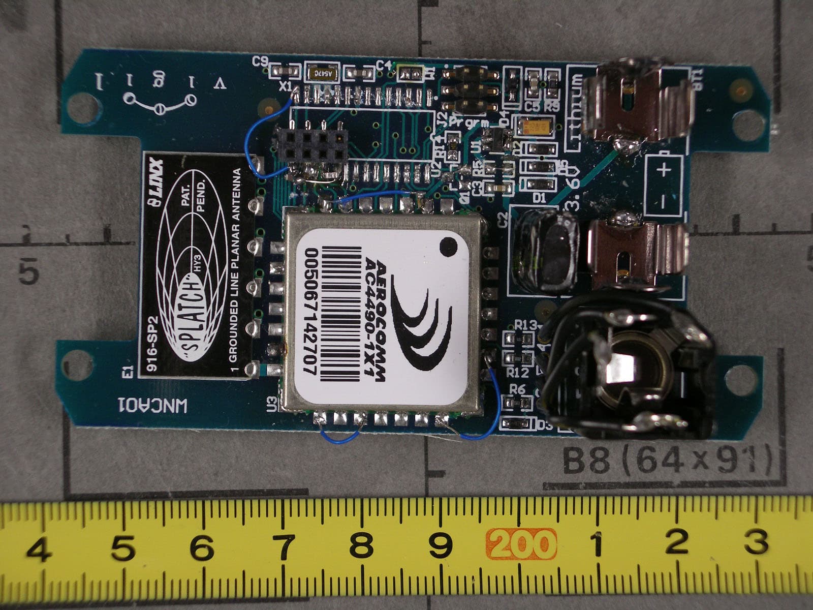
Click to zoom
Application Details
- Equipment Class
- DSS - Part 15 Spread Spectrum Transmitter
- Date of Grant
- Oct 05, 2006
- Application Purpose
- Original Equipment
- Date of Application
- Oct 05, 2006
- Equipment Note
- Low Power Transmitter
- Frequency Range
- 902.30000000 - 927.60000000
- Company
- Vigil Health Solutions Inc
- Country
- Canada
Documents & Files
Document Text
Text extracted from the exhibit documents filed with the FCC. Open a document above to read the original.
Users Manual
Vigil Wireless Call Station Installation Instructions Vigil Health Solutions Inc. Page 1 2102 - 4464 Markham Street * Victoria, BC * Canada * V8Z 7X8 Phone: 250.383.6900 Toll Free: 1.877.850.1122 Fax: 250.383.6999 Web: www.vigil.com REV: JUL2006 V V i i g g i i l l ® ® W W i i r r e e l l e e s s s s C C a a l l l l S S t t a a t t i i o o n n W W N N C C Description The Vigil ® Wireless Nurse Call Station is designed for use with the Vigil ® Wireless System. Wireless Nurse Call Stations are splash resistant and suitable for mounting in resident rooms, dining rooms, common areas and corridors. The Call Station has a touch sensitive green CALL button with call-placed LED. An optional call cord socket can be used to connect push button or geriatric call cords. Call stations also have a touch-sensitive Cancel button to cancel calls at the point of origin. Operation To place a call, the user simply presses the green CALL button or activates the call cord. When the Call Station receives confirmation from the system that the signal has been received, the LED will flash Green. The confirmation process usually takes less than one second. If for any reason the call station is out of range, or the signal is not confirmed, the LED will flash Red to notify the user to try again. If the call is successful, the Green LED will continue to flash intermittently until the call is cancelled at the station. To cancel the call, the responding staff member presses the cancel ‘C’ button. For stations equipped with call cord sockets, a “Call Cord Out” call will be raised if the call cord is removed from the socket. This ensures that staff are alerted if a resident accidentally pulls the call cord from the station. “Call Cord Out” calls can be cancelled either by replacing the call cord or by pressing the cancel button. No dummy plugs are required if the call cord is removed and the call is cancelled. When a Call Station is activated, the signal is sent to the nearest receiver, which then sends a message to the Vigil Central Computer. The call is displayed on the Vigil ® Active Calls Screen and is also sent to designated pagers or wireless phones. Using the Vigil ® Calls software, the active calls can be displayed on any computer in the building that is on the facility’s network. The call information displayed on the Active Calls Screen includes the type of call, the location of the call station, the time the call was activated and the number of subsequent repeat calls that were sent if the call is not cancelled right away. When the battery level drops to the minimum operating level, a Low Battery alert will be generated. The Low Battery alert will be displayed on the Vigil Calls screen and can also be sent to pagers or phones. See the Specifications section for battery details and instructions for replacing batteries. Features Intelligent Transceiver Technology Cancel at Origin of Call Visual Confirmation of Signal Reception Visual Indication when Station Active Visual Confirmation when Call Cancelled Optional Call Cord Socket Variety of Call Cords Available Long Life Battery Low Battery Alert Vigil Wireless Call Station Installation Instructions Vigil Health Solutions Inc. Page 2 2102 - 4464 Markham Street * Victoria, BC * Canada * V8Z 7X8 Phone: 250.383.6900 Toll Free: 1.877.850.1122 Fax: 250.383.6999 Web: www.vigil.com REV: JUL2006 Installation Instructions Wireless call stations are typically mounted in a single gang surface mount wall box. Follow the instructions below when installing a station: 1. Mount wall box on wall using suitable screws for the type of construction. 2. Insert battery into station observing correct polarity. Observe the LED’s on the device. When the battery is first installed you will see the Green LED blink on and off for about 30 seconds followed by one longer blink and then a very short blink. This sequence indicates that the device has successfully found the network. If the station blinks RED refer to the Troubleshooting guide. 3. Record Serial # (Transmitter ID#) from back of device. Location of the serial number is shown below. 4. Screw mount the station to the wall box. Do not mount Wireless Stations on or near metal objects (HVAC, I Beams, etc) or electrical devices (motors, high voltage switching, etc) as they can interfere with the wireless signals Location of serial number The last six digits of the serial number (“142431” in the example) are needed when configuring the Vigil Central Computer. The Splatch antenna model 916-SP2 is permanently attached to the circuit board. Caution: Any changes or modifications not expressly approved by the party responsible for compliance could void the user's authority to operate the equipment. Specifications PHYSICAL ELECTRICAL Height 127mm (5.0”) Operating Voltage 3.3V Width 83mm (3.26”) Wireless 900MHz FHSS Transceiver Depth 38mm (1.5”) Standing Current 20mA Weight 153 grams Operating Current 40mA TX/RX Enclosure High impact white plastic enclosure Battery Type 1/2AA 3.6V Lithium Accessories Optional Call Cords Battery Life 5-8 yrs average use Temperature Ratings Operating: Storage/Transport -0°C to 50°C (32°F to 122°F) -55°C to 85°C (-67°F to 185°F) FCC ID UI6-WNCA01 To replace battery, remove the surrounding faceplate and unscrew the station from the wall box. Replace with same battery type, observing polarity. Take care when handling the circuit board. Replace screws and faceplate. Compliance: This Device complies with Part 15 of the FCC Rules. Operation is subject to the following two conditions: (1) This device may not cause harmful interference, and (2) This device must accept any interference received, including interference that may cause undesired operation.
Cover Letter(s)
Federal Communications Commission 445 12 th Street SW Washington, DC 20554 USA Request for Confidentiality in accordance with CFR 0.457 and 0.459 07 September 2006 EMCCert DR. RAŠEK - Certification Institute - Boelwiese 5 D-91320 Ebermannstadt RE: Certification Application FCC ID: UI6-WNCA01 Please be advised that the following information is to be held confidential on behalf of Vigil Health Solutions Inc.: • Schematics • Parts List • Block Diagram • Technical Description The application contains technical information which Vigil Health Solutions Inc. deems to be trade secrets and proprietary. If made public, the information might be used to the disadvantage of the applicant in the market place. Thank you for your attention to this matter.
ID Label/Location Info
FCC ID UI6-WNCA01 This device complies with Part 15 of the FCC Rules. Operation is subject to the following two conditions: (1) this device may not cause harmful interference, and (2) this device must accept any interference received, including interference that may cause undesired operation. IC: 6706A-WNCA01
Internal Photos
FCC ID: UI6-WNCA01 FCC ID: UI6-WNCA01
Test Report
Senton GmbH Aeussere Fruehlingstrasse 45 D-94315 Straubing Note: The test data of this report is related only to the individual item which has been tested. This report shall not be reproduced except in full extent without the written approval of the testing laboratory. Test Report No. 57403-060316-1 (Edition 1) Page 1 of 62 Pages Straubing, 02 August 2006 T E S T - R E P O R T No. 57403-060316-1 (Edition 1) for WNCA01 Nurse Call Transceiver Applicant: Vigil Health Solutions Inc. Test Specifications: FCC Code of Federal Regulations, CFR 47, Part 15, Sections 15.107, 15.109, 15.207 15.215 and 15.247 Industry Canada Radio Standards Specifications RSS-Gen Issue 1, Sectons 7.2.2, 7.2.3 and RSS-210 Issue 6, Section A8 (Category I Equipment) Senton GmbH Aeussere Fruehlingstrasse 45 D-94315 Straubing Test Report No. 57403-060316-1 (Edition 1) Page 2 of 62 Pages Table of Contents 1 Description of the Equipment Under Test (EUT) ........................................................ 3 2 Administrative Data..................................................................................................... 4 3 Identification of the Test Laboratory ........................................................................... 5 4 Summary .................................................................................................................... 6 5 Operation Mode and Configuration of EUT................................................................. 7 6 Measurement Procedures........................................................................................... 8 6.1 Bandwidth Measurements .................................................................................... 8 6.2 Radiated Emission in Fully or Semi Anechoic Room............................................ 9 6.3 Radiated Emission at Open Field Test Site........................................................ 11 7 Photographs Taken During Testing .......................................................................... 12 8 Test Results .............................................................................................................. 16 8.1 Occupied Bandwidth........................................................................................... 18 8.2 Bandwidth of the Emission ................................................................................. 29 8.3 Designation of Emissions ................................................................................... 33 8.4 Channel Bandwidth ............................................................................................ 34 8.5 Hopping Channel Separation ............................................................................. 35 8.6 Number of Hopping Frequencies........................................................................ 39 8.7 Time Occupancy on any Channel ...................................................................... 41 8.8 Carrier Power ..................................................................................................... 48 8.9 Spurious emissions 30 MHz to 10 GHz - radiated.............................................. 50 8.10 RF-Exposure ...................................................................................................... 56 8.11 Exposure of Humans to RF Fields...................................................................... 57 9 Test Results for Receiver.......................................................................................... 59 9.1 Radiated Emission Measurement 30 MHz to 5 GHz ......................................... 60 10 Referenced Regulations ........................................................................................... 61 11 Charts taken during Testing...................................................................................... 62 Senton GmbH Aeussere Fruehlingstrasse 45 D-94315 Straubing Test Report No. 57403-060316-1 (Edition 1) Page 3 of 62 Pages 1 Description of the Equipment Under Test (EUT) General data of EUT Type designation 1 : WNCA01 Parts 2 : Serial number(s): --- Manufacturer: Vigil Health Solutions Inc. Type of equipment: Nurse Call Transceiver Version: As delivered FCC ID: Additional parts/accessories: --- Technical data of EUT Application frequency range: 902 - 928 MHz Frequency range: 902 - 928 MHz Operating frequency: 915 MHz Type of modulation: FM Pulse train: --- Pulse width: --- Number of RF-channels: --- Channel spacing: --- Designation of emissions 3 : 250kF1D Type of antenna: Integrated Size/length of antenna: Connection of antenna: detachable not detachable Type of power supply: Battery supply - lithium type Specifications for power supply: nominal voltage: 3.6 V 1 Type designation of the system if EUT consists of more than one part. 2 Type designations of the parts of the system, if applicable. 3 Also known as "Class of Emission". Senton GmbH Aeussere Fruehlingstrasse 45 D-94315 Straubing Test Report No. 57403-060316-1 (Edition 1) Page 4 of 62 Pages 2 Administrative Data Application details Applicant (full address): Vigil Health Solutions Inc. 2102-4464 Markham Street V8Z 7X8 Victoria British Columbia Canada Contact person: Steven Smith Contract identification: Receipt of EUT: 30 June 2006 Date(s) of test: July - August 2006 Note(s): --- Report details Report number: 57403-060316-1 Edition: 1 Issue date: 02 August 2006 Senton GmbH Aeussere Fruehlingstrasse 45 D-94315 Straubing Test Report No. 57403-060316-1 (Edition 1) Page 5 of 62 Pages 3 Identification of the Test Laboratory Details of the Test Laboratory Company name: Senton GmbH EMI/EMC Test Center Address: Aeussere Fruehlingstrasse 45 D-94315 Straubing Germany Laboratory accreditation: DAR-Registration No. DAT-P-171/94-02 FCC test site registration number 90926 Industry Canada test site registration: IC 3050 Contact person: Mr. Johann Roidt Phone: (+49) (0)9421 5522-0 Fax: (+49) (0)9421 5522-99 Senton GmbH Aeussere Fruehlingstrasse 45 D-94315 Straubing…
Text truncated - open the document above for the full version.
Test Report
Senton GmbH Aeussere Fruehlingstrasse 45 D-94315 Straubing Note: The test data of this report is related only to the individual item which has been tested. This report shall not be reproduced except in full extent without the written approval of the testing laboratory. Test Report No. 57403-060316-1 (Edition 2) Page 1 of 64 Pages Straubing, 12 September 2006 T E S T - R E P O R T No. 57403-060316-1 (Edition 2) for WNCA01 Nurse Call Transceiver Applicant: Vigil Health Solutions Inc. Test Specifications: FCC Code of Federal Regulations, CFR 47, Part 15, Sections 15.107, 15.109, 15.207 15.215 and 15.247 Industry Canada Radio Standards Specifications RSS-Gen Issue 1, Sectons 7.2.2, 7.2.3 and RSS-210 Issue 6, Section A8 (Category I Equipment) Senton GmbH Aeussere Fruehlingstrasse 45 D-94315 Straubing Test Report No. 57403-060316-1 (Edition 2) Page 2 of 64 Pages Table of Contents 1 Description of the Equipment Under Test (EUT) ........................................................ 3 2 Administrative Data..................................................................................................... 4 3 Identification of the Test Laboratory ........................................................................... 5 4 Summary .................................................................................................................... 6 5 Operation Mode and Configuration of EUT................................................................. 7 6 Measurement Procedures........................................................................................... 8 6.1 Bandwidth Measurements .................................................................................... 8 6.2 Radiated Emission in Fully or Semi Anechoic Room............................................ 9 6.3 Radiated Emission at Open Field Test Site........................................................ 11 7 Photographs Taken During Testing .......................................................................... 12 8 Test Results for Transmitter ..................................................................................... 16 8.1 Occupied Bandwidth........................................................................................... 18 8.2 Bandwidth of the Emission ................................................................................. 29 8.3 Designation of Emissions ................................................................................... 33 8.4 Channel Bandwidth ............................................................................................ 34 8.5 Hopping Channel Separation ............................................................................. 35 8.6 Number of Hopping Frequencies........................................................................ 39 8.7 Time Occupancy on any Channel ...................................................................... 41 8.8 Carrier Power ..................................................................................................... 48 8.9 Spurious emissions 30 MHz to 10 GHz - radiated.............................................. 52 8.10 RF-Exposure ...................................................................................................... 58 8.11 Exposure of Humans to RF Fields...................................................................... 59 9 Test Results for Receiver.......................................................................................... 61 9.1 Radiated Emission Measurement 30 MHz to 5 GHz ......................................... 62 10 Referenced Regulations ........................................................................................... 63 11 Charts taken during Testing...................................................................................... 64 Senton GmbH Aeussere Fruehlingstrasse 45 D-94315 Straubing Test Report No. 57403-060316-1 (Edition 2) Page 3 of 64 Pages 1 Description of the Equipment Under Test (EUT) General data of EUT Type designation 1 : WNCA01 Parts 2 : Serial number(s): --- Manufacturer: Vigil Health Solutions Inc. Type of equipment: Nurse Call Transceiver Version: As delivered FCC ID: Additional parts/accessories: --- Technical data of EUT Application frequency range: 902 - 928 MHz Frequency range: 902 - 928 MHz Operating frequency: 915 MHz Type of modulation: FM Pulse train: --- Pulse width: --- Number of RF-channels: --- Channel spacing: --- Designation of emissions 3 : 250kF1D Type of antenna: Integrated Size/length of antenna: Connection of antenna: detachable not detachable Type of power supply: Battery supply - lithium type Specifications for power supply: nominal voltage: 3.6 V 1 Type designation of the system if EUT consists of more than one part. 2 Type designations of the parts of the system, if applicable. 3 Also known as "Class of Emission". Senton GmbH Aeussere Fruehlingstrasse 45 D-94315 Straubing Test Report No. 57403-060316-1 (Edition 2) Page 4 of 64 Pages 2 Administrative Data Application details Applicant (full address): Vigil Health Solutions Inc. 2102-4464 Markham Street V8Z 7X8 Victoria British Columbia Canada Contact person: Steven Smith Contract identification: Receipt of EUT: 30 June 2006 Date(s) of test: July - August 2006 Note(s): --- Report details Report number: 57403-060316-1 Edition: 2 Issue date: 12 September 2006 Senton GmbH Aeussere Fruehlingstrasse 45 D-94315 Straubing Test Report No. 57403-060316-1 (Edition 2) Page 5 of 64 Pages 3 Identification of the Test Laboratory Details of the Test Laboratory Company name: Senton GmbH EMI/EMC Test Center Address: Aeussere Fruehlingstrasse 45 D-94315 Straubing Germany Laboratory accreditation: DAR-Registration No. DAT-P-171/94-02 FCC test site registration number 90926 Industry Canada test site registration: IC 3050 Contact person: Mr. Johann Roidt Phone: (+49) (0)9421 5522-0 Fax: (+49) (0)9421 5522-99 Senton GmbH Aeussere Fruehlingstrasse 45 D-94315 Straubing Te…
Text truncated - open the document above for the full version.
Test Setup Photos
Senton GmbH Aeussere Fruehlingstrasse 45 D-94315 Straubing Test Report No. 57403-060316-1 (Edition 1) Page 13 of 62 Pages Test setup for radiated emission measurement (fully anechoic room) Senton GmbH Aeussere Fruehlingstrasse 45 D-94315 Straubing Test Report No. 57403-060316-1 (Edition 1) Page 14 of 62 Pages Test setup for radiated emission measurement (open field test site) Senton GmbH Aeussere Fruehlingstrasse 45 D-94315 Straubing Test Report No. 57403-060316-1 (Edition 1) Page 15 of 62 Pages Test setup for radiated emission measurement (open field test site) - continued -
Contact Information
Applicant
Steven Scott Smith(VP Development)
Test Firm
TUV SUD Product Service GmbH PS-EMC-STRRainer Heller
Technical Specifications
| # | Rule Parts | Frequency Range | Power Output |
|---|---|---|---|
| 1 | 15C | 902.3 MHz - 927.6 MHz | 12.20 mW |
Other Applications from Vigil Health Solutions Inc
UI6-ZRF
Jun 17, 2013Vitalilty Wireless RF Module (ZRF)
Equipment Class
DTS - Digital Transmission System
UI6-WRX01
Oct 08, 2006Low Power Transmitter
Equipment Class
DSS - Part 15 Spread Spectrum Transmitter