UI6-WRX01Low Power Transmitter
Vigil Health Solutions Inc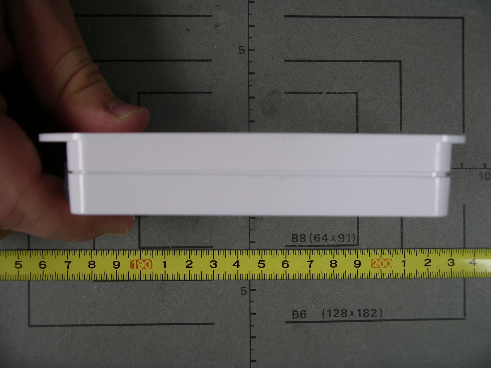
Click to zoom
Application Details
- Equipment Class
- DSS - Part 15 Spread Spectrum Transmitter
- Date of Grant
- Oct 08, 2006
- Application Purpose
- Original Equipment
- Date of Application
- Oct 08, 2006
- Equipment Note
- Low Power Transmitter
- Frequency Range
- 902.20000000 - 927.40000000
- Company
- Vigil Health Solutions Inc
- Country
- Canada
Documents & Files
Document Text
Text extracted from the exhibit documents filed with the FCC. Open a document above to read the original.
Users Manual
Wireless Receiver Installation Instructions Vigil Health Solutions Inc. Page 1 2102 - 4464 Markham Street * Victoria, BC * Canada * V8Z 7X8 Phone: 250.383.6900 Toll Free: 1.877.850.1122 Fax: 250.383.6999 Web: www.vigil.com Revised: June 26, 2006 W W i i r r e e l l e e s s s s R R e e c c e e i i v v e e r r a a n n d d S S e e r r v v e e r r W W R R X X & & W W S S R R X X Description The Wireless Receiver (WRX) receives wireless transmissions from wireless devices and communicates the data back to the central computer via the network cable. Wireless Receivers are connected in series using a CAT5 cable and are terminated with RJ45 modular plugs. One Wireless Receiver covers an area of approximately 100 feet square depending on building construction. The Wireless Server Receiver (WSRX) is a variation of the Wireless Receiver that controls the wireless portion of the communications. Typically one WSRX is required per building. Mounting Instructions Screw mount to wall or ceiling using mounting holes and appropriate mounting hardware for location. Mounting hardware not supplied. Typically mounted above the ceiling tile in a corridor. Mount vertically on the wall above the ceiling tile, with the antenna pointing downward. Antenna does not need to protrude below tile. Alternately, receivers can be mounted below the ceiling or on the ceiling. See below for mounting orientation options. If mounting on a horizontal surface a 90-degree antenna will be required. Screw antenna onto WRX. Position 90-degree antenna vertically as appropriate. Do not mount Wireless Receivers on or near metal objects (HVAC, I Beams, etc) or electrical devices (motors, high voltage switching, etc) as they can interfere with the wireless signals Enclosure Dimensions 5.5” x 3” x 1” Antenna 6.25” Detachable Nearson 900MHz ISM Band. Model 161. Cable Type CAT5 or CAT5E 4 Pair 24AWG Connectors RJ45 Modular Plug (AMP) WRX with straight antenna WRX with 90° antenna Wireless Receiver Installation Instructions Vigil Health Solutions Inc. Page 2 2102 - 4464 Markham Street * Victoria, BC * Canada * V8Z 7X8 Phone: 250.383.6900 Toll Free: 1.877.850.1122 Fax: 250.383.6999 Web: www.vigil.com Revised: June 26, 2006 Wiring and Connections Installation Instructions 1. Terminate incoming and outgoing CAT5 cables on RJ45 modular plugs as shown above. Use supplied AMP plugs or approved equivalent. Ensure cables are labelled appropriately. 2. After connecting the modular plugs on both ends of the cable, use an approved network cable tester to verify the connections on both ends. All pins must be connected straight through. 3. Once both ends of the cable are tested, plug the cable coming from the direction of the central equipment into the socket marked “IN” and plug the cable going to the next receiver into the socket marked “OUT”. 4. Set dipswitches as follows: a. If receiver is at the end of the line (no outgoing run) set the Terminating Resistor to ON by turning the switch labelled “T” toward the base of the unit (labelled ON) b. If the receiver is a WSRX (Server) set the unit to Server mode by turning the switch labelled “S” toward the base of the unit (labelled ON) Caution: Any changes or modifications not expressly approved by the party responsible for compliance could void the user's authority to operate the equipment. Conductor Use Orange/ White + 24 VDC Orange + 24 VDC Green/ White + 24 VDC Blue DATA HI Blue/ White DATA LO Green GND Brown/ White GND Brown GND RJ45 Standard Pinout Hook is underneath 1 Orange/ White 2 Orange 3 Green/ White 4 Blue 5 Blue/ White 6 Green 7 Brown/ White 8 Brown Receiver ID Turn T Switch to ON if at end of line Turn S Switch to ON if settin g to a Server CAN Bus Communication LED Wireless Communication LED Wireless Receiver Installation Instructions Vigil Health Solutions Inc. Page 3 2102 - 4464 Markham Street * Victoria, BC * Canada * V8Z 7X8 Phone: 250.383.6900 Toll Free: 1.877.850.1122 Fax: 250.383.6999 Web: www.vigil.com Revised: June 26, 2006 PHYSICAL ELECTRICAL Height 139.7mm (5.5”) Operating Voltage 10-40V DC Width 76.2mm (3”) Wireless 900MHz FHSS Transceiver Depth 25.4mm (1”) Operating Current 35mA, 85mA burst Weight (with antenna) 141 grams Enclosure High impact white plastic enclosure WRX01 – FCC ID UI6-WRX01 Temperature Ratings Operating: Storage/Transport -0°C to 50°C (32°F to 122°F) -55°C to 85°C (-67°F to 185°F) WSRX01 – FCC ID KQL-AC4490 Compliance: This Device complies with Part 15 of the FCC Rules. Operation is subject to the following two conditions: (1) This device may not cause harmful interference, and (2) This device must accept any interference received, including interference that may cause undesired operation. Warning: This equipment has been approved for portable applications where the equipment can be used in direct contact with the human body. Excessive RF exposure should be avoided. Limited Warranty Vigil ® Health Solutions Inc. (Vigil) warrants all products bearing the Vigil ® name (“the Product” or “Products”) to be in conformance with specifications and free from defects in materials and workmanship for a period of one (1) year (unless otherwise stated) from date of shipment and will repair o r replace (at our option), any unit that is found to be defective and returned to us under warranty. To exercise the warranty the product must be returned to Vigil freight prepaid and insured. Vigil reserves the right to make the final decision whethe r there is a defect in materials or workmanship, and whether or not the product returned is within the warranty. This warranty does not cover damage due to normal wear and tear, improper installation, accident or tampering, misuse or neglect, or where goods have been subjected to operating or environmental conditions exceeding those stated in the applicable specifications and extends to include floods, fire, lightening and any other such acts of nature. This warranty shall apply to the Product only. All other products distributed b…
Text truncated - open the document above for the full version.
Cover Letter(s)
Federal Communications Commission 445 12 th Street SW Washington, DC 20554 USA Request for Confidentiality in accordance with CFR 0.457 and 0.459 07 September 2006 EMCCert DR. RAŠEK - Certification Institute - Boelwiese 5 D-91320 Ebermannstadt RE: Certification Application FCC ID: UI6-WRX01 Please be advised that the following information is to be held confidential on behalf of Vigil Health Solutions Inc.: • Schematics • Parts List • Block Diagram • Technical Description The application contains technical information which Vigil Health Solutions Inc. deems to be trade secrets and proprietary. If made public, the information might be used to the disadvantage of the applicant in the market place. Thank you for your attention to this matter.
External Photos
FCC ID: UI6-WRX01 FCC ID: UI6-WRX01 FCC ID: UI6-WRX01 FCC ID: UI6-WRX01 FCC ID: UI6-WRX01 FCC ID: UI6-WRX01 FCC ID: UI6-WRX01
ID Label/Location Info
Model: WRX01 This device complies with Part 15 of the FCC Rules. Operation is subject to the following two conditions: (1) this device may not cause harmful interference, and (2) this device must accept any interference received, including interference that may cause undesired operation. IC: 6706A-WRX01 FCC ID UI6-WRX01
Internal Photos
FCC ID: UI6-WRX01 FCC ID: UI6-WRX01
Test Report
Senton GmbH Aeussere Fruehlingstrasse 45 D-94315 Straubing Note: The test data of this report is related only to the individual item which has been tested. This report shall not be reproduced except in full extent without the written approval of the testing laboratory. Test Report No. 57403-060316-2 (Edition 2) Page 1 of 74 Pages Straubing, 13 September 2006 T E S T - R E P O R T No. 57403-060316-2 (Edition 2) for WRX01 Nurse Call Transceiver Applicant: Vigil Health Solutions Inc. Test Specifications: FCC Code of Federal Regulations, CFR 47, Part 15, Sections 15.107, 15.109, 15.207 15.215 and 15.247 Industry Canada Radio Standards Specifications RSS-Gen Issue 1, Sectons 7.2.2, 7.2.3 and RSS-210 Issue 6, Section A8 (Category I Equipment) Senton GmbH Aeussere Fruehlingstrasse 45 D-94315 Straubing Test Report No. 57403-060316-2 (Edition 2) Page 2 of 74 Pages Table of Contents 1 Description of the Equipment Under Test (EUT) ........................................................ 3 2 Administrative Data..................................................................................................... 4 3 Identification of the Test Laboratory ........................................................................... 5 4 Summary .................................................................................................................... 6 5 Operation Mode and Configuration of EUT................................................................. 7 6 Measurement Procedures........................................................................................... 8 6.1 Bandwidth Measurements .................................................................................... 9 6.2 Conducted AC Powerline Emission .................................................................... 10 6.3 Radiated Emission in Fully or Semi Anechoic Room.......................................... 12 6.4 Radiated Emission at Open Field Test Site........................................................ 14 7 Photographs Taken During Testing .......................................................................... 15 8 Test Results for Transmitter ..................................................................................... 20 8.1 Occupied Bandwidth........................................................................................... 22 8.2 Bandwidth of the Emission ................................................................................. 33 8.3 Designation of Emissions ................................................................................... 37 8.4 Conducted Powerline Emission Measurement 150 kHz to 30 MHz................... 38 8.5 Channel Bandwidth ............................................................................................ 40 8.6 Hopping Channel Separation ............................................................................. 41 8.7 Number of Hopping Frequencies........................................................................ 45 8.8 Time Occupancy on any Channel ...................................................................... 47 8.9 Carrier Power Measurment ................................................................................ 54 8.10 Spurious emissions 30 MHz to 10 GHz - conducted .......................................... 58 8.11 Spurious emissions 30 MHz to 10 GHz - radiated.............................................. 64 8.12 RF-Exposure ...................................................................................................... 68 8.13 Exposure of Humans to RF Fields...................................................................... 69 9 Test Results for Receiver.......................................................................................... 71 9.1 Radiated Emission Measurement 30 MHz to 5 GHz ......................................... 72 10 Referenced Regulations ........................................................................................... 73 11 Charts taken during testing ....................................................................................... 74 Senton GmbH Aeussere Fruehlingstrasse 45 D-94315 Straubing Test Report No. 57403-060316-2 (Edition 2) Page 3 of 74 Pages 1 Description of the Equipment Under Test (EUT) General data of EUT Type designation 1 : WRX01 Parts 2 : Serial number(s): Manufacturer: Vigil Health Solutions Inc. Type of equipment: Nurse Call Transceiver Version: As delivered FCC ID: Additional parts/accessories: --- Technical data of EUT Application frequency range: 902 - 928 MHz Frequency range: 902 - 928 MHz Operating frequency: 915 MHz Type of modulation: FM Pulse train: --- Pulse width: --- Number of RF-channels: --- Channel spacing: --- Designation of emissions 3 : 250kF1D Type of antenna: Monopole Size/length of antenna: 16.5 cm Connection of antenna: detachable not detachable Antenna connector: Reverse Polarity SMA Type of power supply: Battery supply - lithium type Specifications for power supply: nominal voltage: 3.6 V 1 Type designation of the system if EUT consists of more than one part. 2 Type designations of the parts of the system, if applicable. 3 Also known as "Class of Emission". Senton GmbH Aeussere Fruehlingstrasse 45 D-94315 Straubing Test Report No. 57403-060316-2 (Edition 2) Page 4 of 74 Pages 2 Administrative Data Application details Applicant (full address): Vigil Health Solutions Inc. 2102-4464 Markham Street V8Z 7X8 Victoria British Columbia Canada Contact person: Steven Smith Receipt of EUT: 30 June 2006 Date(s) of test: July - August 2006 Note(s): --- Report details Report number: 57403-060316-2 Edition: 2 Issue date: 13 September 2006 Senton GmbH Aeussere Fruehlingstrasse 45 D-94315 Straubing Test Report No. 57403-060316-2 (Edition 2) Page 5 of 74 Pages 3 Identification of the Test Laboratory Details of the Test Laboratory Company name: Senton GmbH EMI/EMC Test Center Address: Aeussere Fruehlingstrasse 45 D-94315 Straubing Germany L…
Text truncated - open the document above for the full version.
Test Setup Photos
Senton GmbH Aeussere Fruehlingstrasse 45 D-94315 Straubing Test Report No. 57403-060316-2 (Edition 1) Page 16 of 74 Pages Test setup for conducted AC powerline emission measurement Senton GmbH Aeussere Fruehlingstrasse 45 D-94315 Straubing Test Report No. 57403-060316-2 (Edition 1) Page 17 of 74 Pages Test setup for radiated emission measurement (fully anechoic room) Senton GmbH Aeussere Fruehlingstrasse 45 D-94315 Straubing Test Report No. 57403-060316-2 (Edition 1) Page 18 of 74 Pages Test setup for radiated emission measurement (open field test site) Senton GmbH Aeussere Fruehlingstrasse 45 D-94315 Straubing Test Report No. 57403-060316-2 (Edition 1) Page 19 of 74 Pages Test setup for radiated emission measurement (open field test site) - continued -
Contact Information
Applicant
Steven Scott Smith(VP Development)
Test Firm
TUV SUD Product Service GmbH PS-EMC-STRRainer Heller
Technical Specifications
| # | Rule Parts | Frequency Range | Power Output |
|---|---|---|---|
| 1 | 15C | 902.2 MHz - 927.4 MHz | 7.80 mW |
Other Applications from Vigil Health Solutions Inc
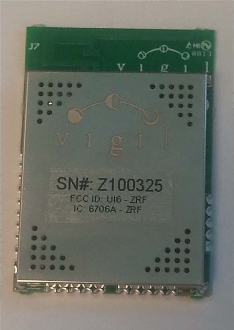
UI6-ZRF
Jun 17, 2013Vitalilty Wireless RF Module (ZRF)
Equipment Class
DTS - Digital Transmission System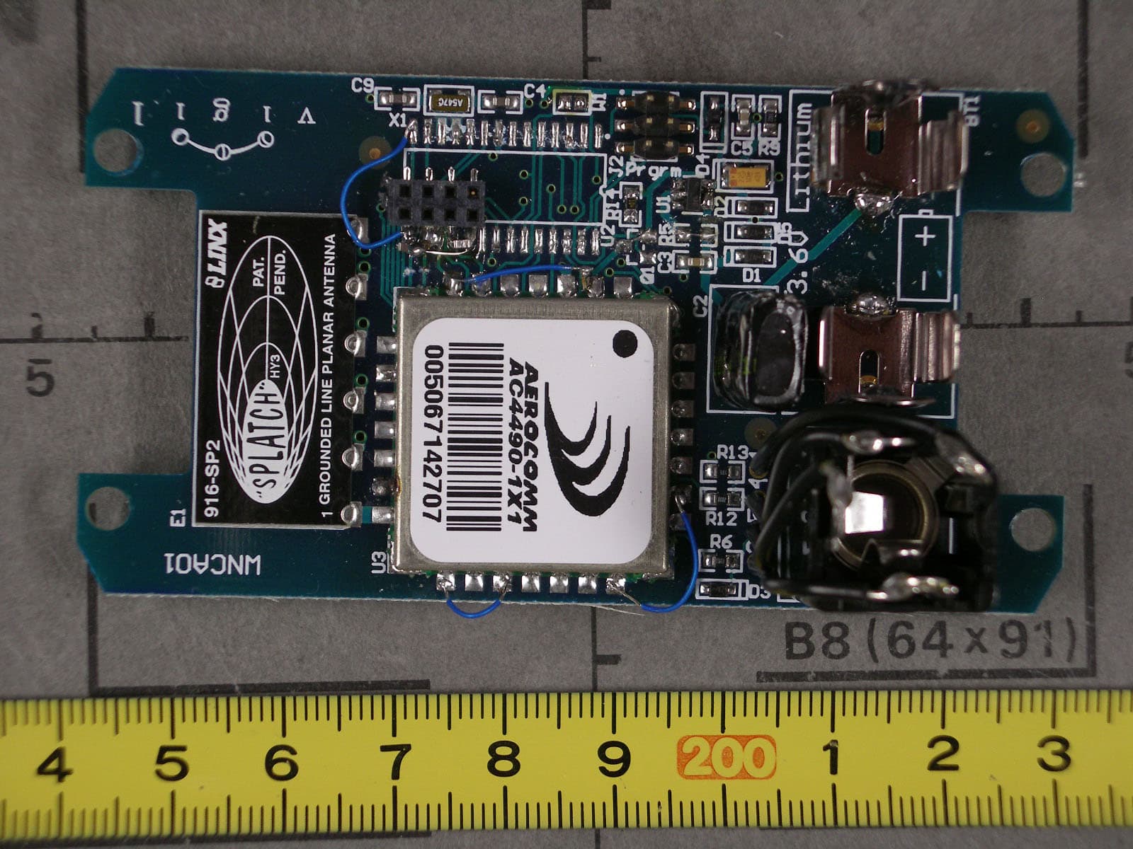
UI6-WNCA01
Oct 05, 2006Low Power Transmitter
Equipment Class
DSS - Part 15 Spread Spectrum Transmitter