Click to zoom
Application Details
- Equipment Class
- DXX - Part 15 Low Power Communication Device Transmitter
- Date of Grant
- Apr 26, 2007
- Application Purpose
- Original Equipment
- Date of Application
- Apr 26, 2007
- Equipment Note
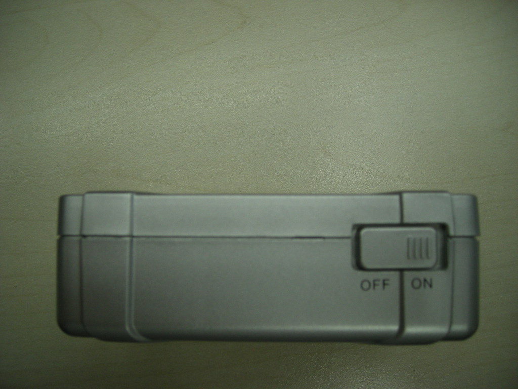
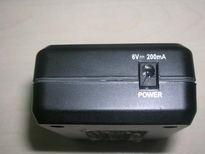
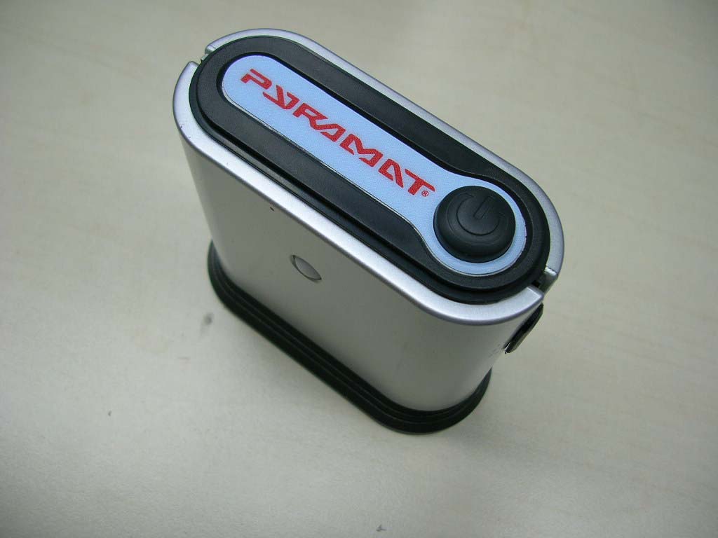
- Sound Rocker Transmitter
- Frequency Range
- 88.10000000 - 88.70000000
- Company
- Pyramat LLC
- Country
- United States
Documents & Files
Select a file to view