UJA0001BFM Transmitter
Pyramat LLC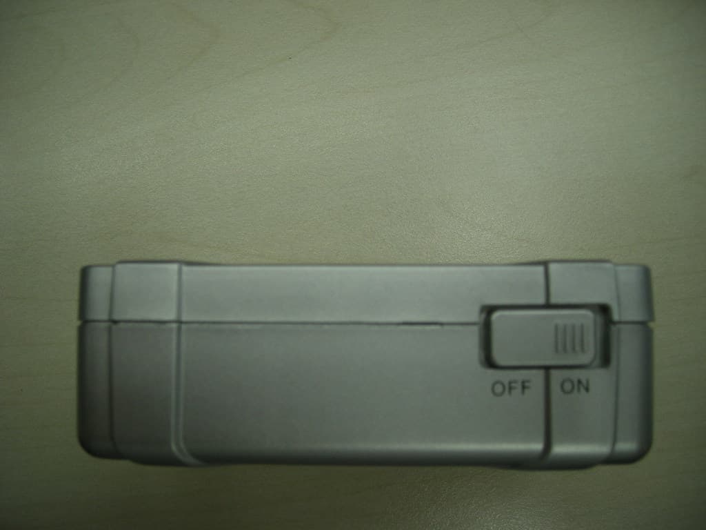
Click to zoom
Application Details
- Equipment Class
- DXX - Part 15 Low Power Communication Device Transmitter
- Date of Grant
- Nov 01, 2007
- Application Purpose
- Original Equipment
- Date of Application
- Nov 01, 2007
- Equipment Note
- FM Transmitter
- Frequency Range
- 106.50000000 - 107.90000000
- Company
- Pyramat LLC
- Country
- United States
Documents & Files
Document Text
Text extracted from the exhibit documents filed with the FCC. Open a document above to read the original.
Users Manual
Français ............Page 14 OWNER’S MANUAL Read and understand this entire manual before using! For assistance contact Pyramat. DO NOT RETURN TO STORE. S2500-W Wireless Sound Rocker Item Number: 10174502 WARNING: The Pyramat Sound Rocker is intended for indoor use only. TO REDUCE THE RISK OF FIRE OR SHOCK HAZARD, DO NOT EXPOSE THIS PRODUCT TO RAIN OR MOISTURE. • Do not expose to direct sunlight or extreme temperatures. • Adult supervision is required for set-up. • Use only with the supplied power adapter. The power adapter is not a toy. • Do not mix old and new batteries. Do not mix alkaline, standard (carbon-zinc), or rechargeable (nickel-cadmium) batteries. • Excessive use of audio equipment at high volume may lead to hearing loss. Listen responsibly and use common sense. • Children under 13 should not use this product without parental supervision. • DO NOT wash or soak the Sound Rocker with water. If cover becomes wet, disconnect power immediately and don’t use until totally dry. • To avoid injury or death from electrical shock, NEVER open the electrical cabinet or remove the cover. The Sound Rocker is compatible with: • All gaming consoles (including Xbox 360 ® , Wii ™ and Playstation 3 ® ) • iPod ® and all other MP3 players • TVs, DVDs, VCRs • Portable gaming devices (including Nintendo DS ® , Nintendo DS Lite ® , and PSP ® ) SAFETY WARNINGS 1 Need Help? Visit our website at www.pyramat.com, send an e-mail to [email protected] or call toll-free at 877-591-1012. CONTENTS Congratulations on the purchase of your Pyramat S2500-W Wireless Sound Rocker. The Sound Rocker is a comfortable, rockable chair that delivers a powerful audio experience designed to intensify your enjoyment of games, movies, music and more. To ensure the best results, please read this manual completely before operating your Sound Rocker, and retain it for future reference. Safety Warnings ............................................................ 1 Before You Begin ...........................................................2 Features .........................................................................2 Sound Rocker Set-Up ....................................................3 Wireless Transmitter Set-Up .........................................4 Wireless Connection Methods ...................................5-6 Direct Connection Methods .......................................7-8 Direct Multi-User Connection .......................................9 Portable Audio/Handheld Game Device Connection .....9 Troubleshooting ...........................................................10 Warranty ......................................................................11 FCC and IC Statement .................................................12 Remove the foam separators from the Sound Rocker and take unit out of box. Check to make sure you have all the parts shown below and that all items are in good condition. BEFORE YOU BEGIN 2 11 ft. male to female RCA audio cable 9 ft. 12-volt DC power adapter Wireless transmitter FEATURES SOUND FURNITURE Control panel Volume/power knob Twist to click on and power up and adjust the volume level. Bass knob Twist to adjust the bass to your preference. MP3 pocket Illuminating speakers Source knob Select IN for direct connections to the control panel. Select W for wireless transmission. Select MP3 for MP3 and portable CD/DVD player connections to the MP3 and portable CD/DVD player plug. Multi-player RCA audio output ports Connect up to four Sound Rockers together for multi-user fun. Input RCA audio ports Connect red and white RCA audio cable here from game consoles, home theater, satellite receiver and stereo receiver. Headphone port Connect headphones here. Channel selector button Select the same channel as the transmitter by pressing the channel selector button. Power DC port Connect supplied 12-volt power adapter here. CAUTION: Keep fingers clear of the folding seam when opening the unit. Note: Replacement cables and mini adapters can be purchased at your local audio accessory dealer or at www.pyramat.com. MP3 and portable CD/DVD player plug RCA to mini audio cable AAA 1.5 Volt batteries (Not included) SET-UP 1 Unfold the top portion of the Sound Rocker until the backrest is flush with the seat portion. Secure velcro tab on the bottom of the rocker. 2 Place the Sound Rocker so that the control panel is less than 9 ft./2.7 meters from the power source. 3 Connect the power adapter to the power DC port on the control panel. Then, plug the power adapter into an electrical outlet. 4 Twist the volume knob on the control panel to click on the power. 5 Check the speakers on top to see if the Pyramat logo is lit up. Twist volume knob to power off the Sound Rocker, then proceed to the connection method shown below for your audio/video device. 9 FEET OR LESS 1 2 3 4 5 6 7 8 3 CAUTION: Keep fingers clear of the folding seam when folding or unfolding the rocker. 4 WIRELESS TRANSMITTER SET-UP 6 Select the same channel as the transmitter on the Sound Rocker’s control panel by pressing the chan- nel button. Example: 1–1, 2–2 or 3–3. To add multiple Sound Rockers, simply select the same channel on each rocker. Note: Both the transmitter and control panel must be on the same channel to hear sound. 1 2 3 4 5 6 7 8 4 Twist the volume knob on the control panel to click on the power. 5 Turn the source knob on the control panel to W. WARNING: Do not mix old and new batteries. Do not mix alkaline, standard (carbon-zinc), or rechargeable (nickel-cadmium) batteries. 1 Remove the casing and insert 2 AAA batteries (batteries not included). 2 Turn the power switch on the front of the transmitter to the “on” position 3 Press the channel button to select the desired transmitter channel. Eight channels are available for the best quality reception. If you experience static or poor reception, try another channel. WIRELESS CONNECTION METHODS 5 Video Game Console Connection Cables XBOX 360 ® , PLAYSTATION 2 ® , PLAYSTATI…
Text truncated - open the document above for the full version.
External Photos
FCC ID: UJA0001B Page 1 of 4 External Picture FCC ID: UJA0001B Page 2 of 4 FCC ID: UJA0001B Page 3 of 4 FCC ID: UJA0001B Page 4 of 4
ID Label/Location Info
FCC ID: UJA0001B Page 1 of 3 FCC ID Label FCC ID: UJA0001B Page 2 of 3 FCC ID: UJA0001B Page 3 of 3
Internal Photos
FCC ID: UJA0001B Page 1 of 2 Internal Picture FCC ID: UJA0001B Page 2 of 2
Operational Description
Operational Description 1. Inset two AA batteries (with 1.5V each) into the EUT. 2. Connect the input terminal of EUT with an ipod which generating 1kHz audio signal. 3. Put the EUT into the semi-anechoic chamber according to the test item. 4. Power on the EUT. 5. Set the EUT at channel 1. 6. Test as the standard required. 7. Repeat above test at channel 8. 8. Test complete. 9. Turn off the EUT.
Schematics
1 2 3 4 56 ABCD 6 5 4 3 2 1 D CBA Title Number Revision Size B Date: 22-Oct-2007 Sheet of File: E:\Li nYi \FM-8\80 11 0NK -8LE D( 原理图 ).DDB Drawn By: C11UF Y17.6MHz C227PF C327PF C40.1UF VCC C90.47UF C54.7UF R1470R L1270NH C100.1UF VCC R2200K C110.1UF VCC L2 180NH C80.1UF VCC C710P C1347P L468NH ANT R856K C204.7NF R668K C161UF AUDIO_L IN_L R756K C194.7NF R568K C151UF AUDIO_R IN_R IN_R IN_L C210.1UF VCC CH2CH3 C18102 C17102 IN_R IN_L IN_LIN_R A_L A_R R433K L3 82NH C32NC VCC C1239P Q19018 CH1 VCC+5 + C347UF/10V VCC CH3CH2CH1CH0DVDD2PVXT_IN XT_OUT VDD1 VDD2 NC VDD3 CP_OUT VCO_P VCO_M VDD4 REF_R EN PA_VDD PA_O IN_L IN_R VDD5 B1 B0 U1 FM80110NK CH1CH2CH3 R12-1 nc C6NA R3 22r L5220nH R13-1 10k VCC R12nc R13 10k R10 10k R9 nc VCC Q?PNP R11560R D5LED D1LED D2LED D3LED P2.2 1 P2.1 2 P2.0 3 VDD 4 XI/P1.3 5 XO/P1.2 6 RST/P1.1 7 P5.4 8 P1.0 9 P0.0/INT 10 GND 11 P2.5 12 P2.4 13 P2.3 14 U2SN8P2051A CH2CH3 CH1 VCC D4LED R8-110K SW2SW-PB VCC VCC D6LED Cm0.1uF D8 LED D7 LED L6 4.7uH C1A8P C2A20P C3A5P R1A470R
Test Report
Report No. JSH007080377-003 Page 1 of 14 EMC TEST REPORT No. JSH007080377-003 Applicant : Pyramat LLC 16200-A Carmenita Rd., Cerritos, California, 90703, United States Manufacturer : Xiamen Comfort Science and Technology Group Co., Ltd. No.18 Longshan South Road, Xiamen 361009, China Equipment : Sound Rocker Transmitter Type/Model : FM Transmitter SUMMARY The equipment complies with the requirements according to the following standard(s): 47CFR Part 15 (2006): Radio Frequency Devices ANSIC63.4 (2003): American National Standard for Methods of Measurement of Radio-Noise Emissions from Low-Voltage Electrical and Electronic Equipment in the Range of 9 kHz to 40 GHz Date of issue: Oct 21, 2007 Tested by: Reviewed by: Wakeyou Wang (Projector Engineer) Jonny Jing (Reviewer) Report No. JSH007080377-003 Page 2 of 14 Description of Test Facility Name: Intertek Testing Services Limited Shanghai Address: Building No.86, 1198 Qinzhou Road(North), Shanghai 200233, P.R. China FCC Registration Number: 236597 IC Assigned Code: 6201A Name of contact: Steve Li Tel: +86 21 64956565 ext. 214 Fax: +86 21 54262335 ext. 214 Report No. JSH007080377-003 Page 3 of 14 Content SUMMARY............................................................................................................................................. 1 DESCRIPTION OF TEST FACILITY............................................................................................................ 2 1. GENERAL INFORMATION............................................................................................................... 4 1.1 Applicant Information..........................................................................................4 1.2 Identification of the EUT .....................................................................................4 1.3 Technical specification ........................................................................................4 1.4 Mode of operation during the test / Test peripherals used...................................5 2. TEST SPECIFICATION..................................................................................................................... 6 2.1 Instrument list ......................................................................................................6 2.2 Test Standard .......................................................................................................6 3. OCCUPIED BANDWIDTH AND FREQUENCY BAND RANGE.............................................................. 8 3.1 Limit.....................................................................................................................8 3.2 Test Configuration ...............................................................................................8 3.3 Test Procedure and test setup...............................................................................8 3.4 Test Protocol ........................................................................................................9 3.5 Measurement uncertainty.....................................................................................9 4. RADIATED EMISSION WITHIN THE PERMITTED 200 KHZ BAND.................................................. 10 4.1 Limit...................................................................................................................10 4.2 Test Configuration .............................................................................................10 4.3 Test Procedure and test setup.............................................................................10 4.4 Test Protocol ......................................................................................................11 4.5 Measurement uncertainty...................................................................................11 5. RADIATED EMISSION OUTSIDE THE PERMITTED 200 KHZ BAND................................................. 12 5.1 Limit...................................................................................................................12 5.2 Test Configuration .............................................................................................12 5.3 Test Procedure and test setup.............................................................................13 5.4 Test Protocol ......................................................................................................13 5.5 Measurement uncertainty...................................................................................14 Report No. JSH007080377-003 Page 4 of 14 1. General Information 1.1 Applicant Information Applicant: Pyramat LLC 16200-A Carmenita Rd., Cerritos, California, 90703, United States Name of contact: Mr. Mike Hsia Tel: 001-562-345-6058 Fax: 001-562-345-6082 Manufacturer: Xiamen Comfort Science and Technology Group Co., Ltd. No.18 Longshan South Road, Xiamen 361009, China Sample received date : Sep 27, 2007 Date of test : Sep 27, 2007~ Oct 17, 2007 1.2 Identification of the EUT Equipment: Sound Rocker Transmitter Type/model: FM Transmitter FCC ID: UJA0001B 1.3 Technical specification Operation Frequency Band: 88MHz ~ 108MHz Modulation: FM Antenna Designation: Inter antennal, Non-User Replaceable (Fixed) Gain of Antenna: 0.5dBi max. Rating: Built-in Battery: DC 2*1.5V, 20mA Description of EUT: The EUT is a transmitter to transmit audio signal to a sound rocker by wireless method. The audio signal generated by TV, DVD, VCR, satellite receiver and etc. is inputted into input terminal of EUT. Report No. JSH007080377-003 Page 5 of 14 Channel Description: There are 8 channels namely channel 1 to channel 8 which indicated by the LED light on the EUT. Here is the channel list: Channel Central frequency (MHz) 1 106.5 2 106.7 3 106.9 4 107.1 5 107.3 6 107.5 7 107.7 8 107.9 We can see that the frequency band is less than 10MHz. As a result, the channel 1 and channel 8 were chosen to perform test as representative. 1.4 Mode of operation during …
Text truncated - open the document above for the full version.
Test Setup Photos
FCC ID: UJA0001B Page 1 of 3 Test Setup FCC ID: UJA0001B Page 2 of 3 Vertical FCC ID: UJA0001B Page 3 of 3 Horizontal
Contact Information
Applicant
Mike Hsia
Technical Contact
IntertekWakeyou Wang
[email protected]86-21-61278448
Building No. 86, 1198 Qinzhou Road (North) · Shanghai · China
Non-Technical Contact
IntertekWakeyou Wang
[email protected]86-21-61278448
Test Firm
Intertek Testing Services Limited ShanghaiJonny Jing
Technical Specifications
| # | Rule Parts | Frequency Range | Power Output |
|---|---|---|---|
| 1 | 15C | 106.5 MHz - 107.9 MHz | - |
Other Applications from Pyramat LLC
UJA0002B
Oct 02, 2007Spread Spectrum Transmitter
Equipment Class
DSS - Part 15 Spread Spectrum Transmitter
UJA0001A
Apr 26, 2007Sound Rocker Transmitter
Equipment Class
DXX - Part 15 Low Power Communication Device Transmitter