UK2-SIL-SK6310060GHz WirelessHD Display Mini Card Transmitter
Lattice Semiconductor Corporation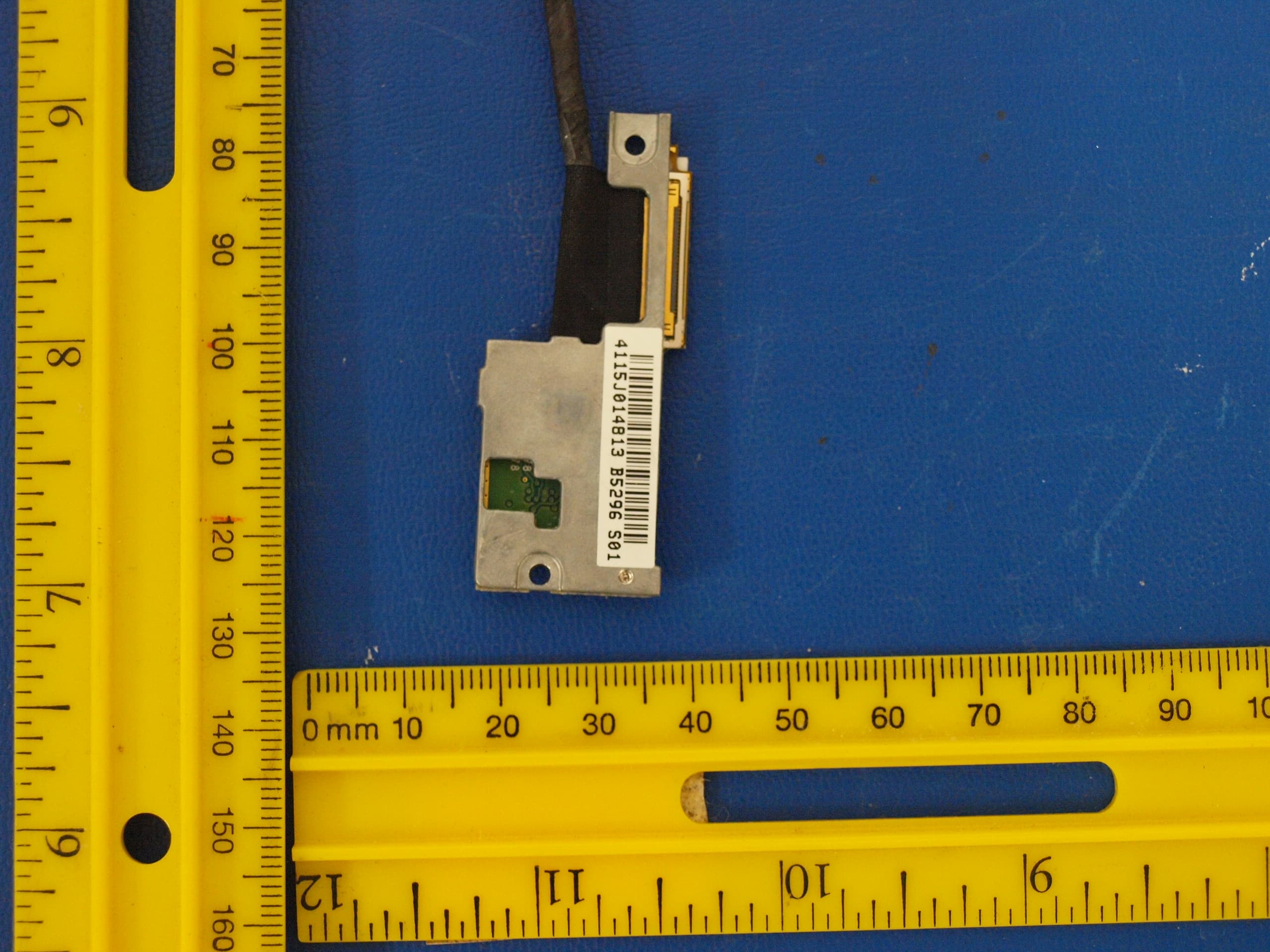
Click to zoom
Application Details
- Equipment Class
- DXX - Part 15 Low Power Communication Device Transmitter
- Date of Grant
- Aug 14, 2013
- Application Purpose
- Original Equipment
- Date of Application
- May 02, 2012
- Equipment Note
- 60GHz WirelessHD Display Mini Card Transmitter
- Frequency Range
- 60480.00000000 - 62640.00000000
- Country
- United States
Documents & Files
Document Text
Text extracted from the exhibit documents filed with the FCC. Open a document above to read the original.
Users Manual
Quick Start Guide WirelessHD Application Controller Introduction: Congratulations on your purchase of this high quality laptop with integrated WirelessHD transmitter, which represents the state of the art in 60GHz wireless video transmission giving you complete freedom to enjoy displaying content from your laptop to a display such as a TV, monitor, or projector without the limitations of cables. The WirelessHD transmitter integrated into your laptop can provide a non line-of-sight transmission range of up to 33 feet (10 m) to a WirelessHD receiver connected to an HDMI- compatible display. This Quick Start Guide provides the basic steps for making a wireless video connection from your laptop with integrated WirelessHD transmitter to a TV, monitor or projector with a connected WirelessHD receiver adapter. Please refer to the documentation that came with your TV, WirelessHD receiver adapter, or WirelessHD transmitter/receiver adapter pair for proper setup, configuration, and operation of these devices. Required Components: 1. A laptop with integrated WirelessHD transmitter 2. A WirelessHD receiver adapter connected to an HDMI-compatible TV or monitor Please note that when you purchased your laptop with integrated WirelessHD transmitter, you may have also purchased a kit containing a WirelessHD transmitter/receiver adapter pair. Follow the instructions provided with that kit to properly connect the WirelessHD receiver adapter to the TV, monitor, or projector. The Wireless transmitter adapter can also be used, if desired, to connect other HDMI-compatible sources such as Blu-ray/DVD players, cable/satellite boxes, or gaming consoles to your TV, monitor, or projector. First Time Connection: Before attempting connection of your laptop with integrated WirelessHD transmitter to your TV, monitor, or projector, please setup and configure the WirelessHD receiver adapter to the TV, monitor, or projector according to the instructions provided with your WirelessHD receiver adapter. 1. Turn on the TV, monitor, or projector and change the input to the HDMI port for which the WirelessHD receiver adapter is connected. 2. Turn on the WirelessHD receiver adapter. 3. Turn on and boot up your laptop system. 4. Launch the WirelessHD Application Controller software from either the Desktop shortcut icon: or from the Start/All Programs/WiHD Controller menu. 5. When the WirelessHD Application Controller software launches, you will see the following window: 6. Ensure that the WiHD transmitter is turned on. The left most of the top three buttons will indicate "Turn WiHD OFF" (see screenshot above) when the transmitter is turned on and enabled. If this button indicates "Turn WiHD ON", the transmitter is turned off therefore press this button once and within a couple seconds the button will change its status to "Turn WiHD OFF" and the WirelessHD transmitter will be turned on and enabled. 7. Click on the Network tab along the left hand side of the application. You will see a window like the following: The MAC address shown for the WVAN (wireless video area network) represents the WVAN ID that is provided from the receiver adapter which is connected to the TV, monitor, or projector. If the WirelessHD receiver adapter is turned on and there is not a MAC address that shows up in the WVAN list, press "Refresh List" to update the list. If there are still issues with getting the WVAN ID, check the connections on the WirelessHD receiver adapter and the antenna orientations of the WirelessHD receiver and your notebook. 8. Select the WVAN ID and then press the "Connect" button as shown below: 9. Within 20 seconds, the notebook screen should be displayed on the TV, monitor, or projector. Note that " (Windows key) + P" keystroke allows selection of duplicate display mode (notebook display and external display contain the same content and resolution) or extended display mode (external display is an extension to the notebook display). 10. The Status tab will reflect something similar as shown below upon a successful connection: Select different mode to other display screen: I. Power on TV/monitor (or other display products) and make sure WirelessHD receiver is activating. II. Open laptop WAC application III. Wait for the laptop and WirelessHD receiver to be associated. IV. Click “Connect” button on the WAC. V. Wait until the connection is successful. VI. Let cursor stay on Windows’ desktop and press right button on the mouse then choosing “screen resolution”. It should detect 2 different displays on it. VII. Select “Duplicate” to let receiver side show the same format on screen. VIII. Wait 30 seconds* for the TV/monitor connection to be successful and stable. Checkpoint: Same Windows desktop should appear on laptop internal display and the TV/monitor. IX. Select “Extend” to cascade the secondary display besides primary one X. Wait 30 seconds* for the TV/monitor connection to be successful and stable. Checkpoint: Extended Windows desktop should appear on laptop internal display and the TV/monitor. *The WirelessHD connection may be lost if display mode switching is too soon before it gets stabilized. OEM Installation Instructions for SIL-SK63100 Module Interference Statement USA - Federal Communications Commission (FCC) This equipment has been tested and found to comply with the limits for a Class B digital device, pursuant to Part 15 of FCC Rules. These limits are designed to provide reasonable protection against harmful interference in a residential installation. This equipment generates, uses, and can radiate radio frequency energy. If not installed and used in accordance with the instructions, it may cause harmful interference to radio communications. However, there is no guarantee that interference will not occur in a particular installation. 1. This device complies with Part 15 of the FCC Rules. Operation is subject to the following two conditions: (1) this device may not cause harmful interference, and (2) this device must accep…
Text truncated - open the document above for the full version.
Users Manual
Quick Start Guide WirelessHD Application Controller Introduction: Congratulations on your purchase of this high quality laptop with integrated WirelessHD transmitter, which represents the state of the art in 60GHz wireless video transmission giving you complete freedom to enjoy displaying content from your laptop to a display such as a TV, monitor, or projector without the limitations of cables. The WirelessHD transmitter integrated into your laptop can provide a non line-of-sight transmission range of up to 33 feet (10 m) to a WirelessHD receiver connected to an HDMI- compatible display. This Quick Start Guide provides the basic steps for making a wireless video connection from your laptop with integrated WirelessHD transmitter to a TV, monitor or projector with a connected WirelessHD receiver adapter. Please refer to the documentation that came with your TV, WirelessHD receiver adapter, or WirelessHD transmitter/receiver adapter pair for proper setup, configuration, and operation of these devices. Required Components: 1. A laptop with integrated WirelessHD transmitter 2. A WirelessHD receiver adapter connected to an HDMI-compatible TV or monitor Please note that when you purchased your laptop with integrated WirelessHD transmitter, you may have also purchased a kit containing a WirelessHD transmitter/receiver adapter pair. Follow the instructions provided with that kit to properly connect the WirelessHD receiver adapter to the TV, monitor, or projector. First Time Connection: Before attempting connection of your laptop with integrated WirelessHD transmitter to your TV, monitor, or projector, please setup and configure the WirelessHD receiver adapter to the TV, monitor, or projector according to the instructions provided with your WirelessHD receiver adapter. 1. Turn on the TV, monitor, or projector and change the input to the HDMI port for which the WirelessHD receiver adapter is connected. 2. Turn on the WirelessHD receiver adapter. 3. Turn on and boot up your laptop system. 4. Launch the WirelessHD Application Controller software from either the Desktop shortcut icon: or from the Start/All Programs/WiHD Controller menu. 5. When the WirelessHD Application Controller software launches, you will see the following window: 6. Ensure that the WiHD transmitter is turned on. The left most of the top three buttons will indicate "Turn WiHD OFF" (see screenshot above) when the transmitter is turned on and enabled. If this button indicates "Turn WiHD ON", the transmitter is turned off therefore press this button once and within a couple seconds the button will change its status to "Turn WiHD OFF" and the WirelessHD transmitter will be turned on and enabled. 7. Click on the Network tab along the left hand side of the application. You will see a window like the following: The MAC address shown for the WVAN (wireless video area network) represents the WVAN ID that is provided from the receiver adapter which is connected to the TV, monitor, or projector. If the WirelessHD receiver adapter is turned on and there is not a MAC address that shows up in the WVAN list, press "Refresh List" to update the list. If there are still issues with getting the WVAN ID, check the connections on the WirelessHD receiver adapter and the antenna orientations of the WirelessHD receiver and your notebook. 8. Select the WVAN ID and then press the "Connect" button as shown below: 9. Within 20 seconds, the notebook screen should be displayed on the TV, monitor, or projector. Note that " (Windows key) + P" keystroke allows selection of duplicate display mode (notebook display and external display contain the same content and resolution) or extended display mode (external display is an extension to the notebook display). 10. The Status tab will reflect something similar as shown below upon a successful connection: Select different mode to other display screen: I. Power on TV/monitor (or other display products) and make sure WirelessHD receiver is activating. II. Open laptop WAC application III. Wait for the laptop and WirelessHD receiver to be associated. IV. Click “Connect” button on the WAC. V. Wait until the connection is successful. VI. Let cursor stay on Windows’ desktop and press right button on the mouse then choosing “screen resolution”. It should detect 2 different displays on it. VII. Select “Duplicate” to let receiver side show the same format on screen. VIII. Wait 30 seconds* for the TV/monitor connection to be successful and stable. Checkpoint: Same Windows desktop should appear on laptop internal display and the TV/monitor. IX. Select “Extend” to cascade the secondary display besides primary one X. Wait 30 seconds* for the TV/monitor connection to be successful and stable. Checkpoint: Extended Windows desktop should appear on laptop internal display and the TV/monitor. *The WirelessHD connection may be lost if display mode switching is too soon before it gets stabilized. OEM Installation Instructions for SIL-SK63100 Module Interference Statement USA - Federal Communications Commission (FCC) This equipment has been tested and found to comply with the limits for a Class B digital device, pursuant to Part 15 of FCC Rules. These limits are designed to provide reasonable protection against harmful interference in a residential installation. This equipment generates, uses, and can radiate radio frequency energy. If not installed and used in accordance with the instructions, it may cause harmful interference to radio communications. However, there is no guarantee that interference will not occur in a particular installation. 1. This device complies with Part 15 of the FCC Rules. Operation is subject to the following two conditions: (1) this device may not cause harmful interference, and (2) this device must accept any interference received, including interference that may cause undesired operation. 2. This product does not contain any user serviceable components. Any unauthorized product changes or modifications will i…
Text truncated - open the document above for the full version.
Users Manual
Quick Start Guide WirelessHD Application Controller Introduction: Congratulations on your purchase of this high quality laptop with integrated WirelessHD transmitter, which represents the state of the art in 60GHz wireless video transmission giving you complete freedom to enjoy displaying content from your laptop to a display such as a TV, monitor, or projector without the limitations of cables. The WirelessHD transmitter integrated into your laptop can provide a non line-of-sight transmission range of up to 33 feet (10 m) to a WirelessHD receiver connected to an HDMI- compatible display. This Quick Start Guide provides the basic steps for making a wireless video connection from your laptop with integrated WirelessHD transmitter to a TV, monitor or projector with a connected WirelessHD receiver adapter. Please refer to the documentation that came with your TV, WirelessHD receiver adapter, or WirelessHD transmitter/receiver adapter pair for proper setup, configuration, and operation of these devices. Required Components: 1. A laptop with integrated WirelessHD transmitter 2. A WirelessHD receiver adapter connected to an HDMI-compatible TV or monitor Please note that when you purchased your laptop with integrated WirelessHD transmitter, you may have also purchased a kit containing a WirelessHD transmitter/receiver adapter pair. Follow the instructions provided with that kit to properly connect the WirelessHD receiver adapter to the TV, monitor, or projector. First Time Connection: Before attempting connection of your laptop with integrated WirelessHD transmitter to your TV, monitor, or projector, please setup and configure the WirelessHD receiver adapter to the TV, monitor, or projector according to the instructions provided with your WirelessHD receiver adapter. 1. Turn on the TV, monitor, or projector and change the input to the HDMI port for which the WirelessHD receiver adapter is connected. 2. Turn on the WirelessHD receiver adapter. 3. Turn on and boot up your laptop system. 4. Launch the WirelessHD Application Controller software from either the Desktop shortcut icon: or from the Start/All Programs/WiHD Controller menu. 5. When the WirelessHD Application Controller software launches, you will see the following window: 6. Ensure that the WiHD transmitter is turned on. The left most of the top three buttons will indicate "Turn WiHD OFF" (see screenshot above) when the transmitter is turned on and enabled. If this button indicates "Turn WiHD ON", the transmitter is turned off therefore press this button once and within a couple seconds the button will change its status to "Turn WiHD OFF" and the WirelessHD transmitter will be turned on and enabled. 7. Click on the Network tab along the left hand side of the application. You will see a window like the following: The MAC address shown for the WVAN (wireless video area network) represents the WVAN ID that is provided from the receiver adapter which is connected to the TV, monitor, or projector. If the WirelessHD receiver adapter is turned on and there is not a MAC address that shows up in the WVAN list, press "Refresh List" to update the list. If there are still issues with getting the WVAN ID, check the connections on the WirelessHD receiver adapter and the antenna orientations of the WirelessHD receiver and your notebook. 8. Select the WVAN ID and then press the "Connect" button as shown below: 9. Within 20 seconds, the notebook screen should be displayed on the TV, monitor, or projector. Note that " (Windows key) + P" keystroke allows selection of duplicate display mode (notebook display and external display contain the same content and resolution) or extended display mode (external display is an extension to the notebook display). 10. The Status tab will reflect something similar as shown below upon a successful connection: Select different mode to other display screen: I. Power on TV/monitor (or other display products) and make sure WirelessHD receiver is activating. II. Open laptop WAC application III. Wait for the laptop and WirelessHD receiver to be associated. IV. Click “Connect” button on the WAC. V. Wait until the connection is successful. VI. Let cursor stay on Windows’ desktop and press right button on the mouse then choosing “screen resolution”. It should detect 2 different displays on it. VII. Select “Duplicate” to let receiver side show the same format on screen. VIII. Wait 30 seconds* for the TV/monitor connection to be successful and stable. Checkpoint: Same Windows desktop should appear on laptop internal display and the TV/monitor. IX. Select “Extend” to cascade the secondary display besides primary one X. Wait 30 seconds* for the TV/monitor connection to be successful and stable. Checkpoint: Extended Windows desktop should appear on laptop internal display and the TV/monitor. *The WirelessHD connection may be lost if display mode switching is too soon before it gets stabilized. OEM Installation Instructions for SIL-SK63100 Module Interference Statement USA - Federal Communications Commission (FCC) This equipment has been tested and found to comply with the limits for a Class B digital device, pursuant to Part 15 of FCC Rules. These limits are designed to provide reasonable protection against harmful interference in a residential installation. This equipment generates, uses, and can radiate radio frequency energy. If not installed and used in accordance with the instructions, it may cause harmful interference to radio communications. However, there is no guarantee that interference will not occur in a particular installation. 1. This device complies with Part 15 of the FCC Rules. Operation is subject to the following two conditions: (1) this device may not cause harmful interference, and (2) this device must accept any interference received, including interference that may cause undesired operation. 2. This product does not contain any user serviceable components. Any unauthorized product changes or modifications will i…
Text truncated - open the document above for the full version.
Cover Letter(s)
Applicant/Grantee SILICON IMAGE FCC ID: UK2-SIL-SK63100 Section 15.212 Modular Transmitters Request for Modular Approval Request for Limited Modular Approval Requirements EUT Conditions Comply (Y/N) Single Modular Approval Requirements 1 The radio elements of the modular transmitter must have their own shielding. The physical crystal and tuning capacitors may be located external to the shielded radio elements. Device is equipped with metal shielding to cover RF section. Refer to external photos. Y 2 The modular transmitter must have buffered modulation/data inputs (if such inputs are provided) to ensure that the module will comply with Part 15 requirements under conditions of excessive data rates or over-modulation. All inputs to the module are buffered through logic or microprocessor inputs. Y 3 The modular transmitter must have its own power supply regulation. Internal 1.0V and 1.2V power regulation provided. Refer to Block diagram. Y 4 The modular transmitter must comply with the antenna and transmission system requirements of Sections 15.203, 15.204(b) and 15.204(c). The antenna must either be permanently attached or employ a “unique” antenna coupler (at all connections between the module and the antenna, including the cable). The “professional installation” provision of Section 15.203 is not applicable to modules but can apply to limited modular approvals under paragraph (b) of this section. Antenna requirements met. Refer to antenna specification provided and test report. Y 5 The modular transmitter must be tested in a stand-alone configuration, i.e., the module must not be inside another device during testing for compliance with Part 15 requirements. Unless the transmitter module will be battery powered, it must comply with the AC line conducted requirements found in Section 15.207. AC or DC power lines and data input/output lines connected to the module must not contain ferrites, unless they will be marketed with the module (see Section 15.27(a)). The length of these lines shall be the length typical of actual use or, if that length is unknown, at least 10 centimeters to insure that there is no coupling between the case of the module and supporting Condition satisfied – Module tested in stand-alone configuration and is not inside another case during testing. Y equipment. Any accessories, peripherals, or support equipment connected to the module during testing shall be unmodified and commercially available (see Section 15.31(i)). 6 The modular transmitter must be equipped with either a permanently affixed label or must be capable of electronically displaying its FCC identification number. (A) If using a permanently affixed label, the modular transmitter must be labeled with its own FCC identification number, and, if the FCC identification number is not visible when the module is installed inside another device, then the outside of the device into which the module is installed must also display a label referring to the enclosed module. This exterior label can use wording such as the following: “Contains Transmitter Module FCC ID: XYZMODEL1” or “Contains FCC ID: XYZMODEL1.” Any similar wording that expresses the same meaning may be used. The Grantee may either provide such a label, an example of which must be included in the application for equipment authorization, or, must provide adequate instructions along with the module which explain this requirement. In the latter case, a copy of these instructions must be included in the application for equipment authorization. (B) If the modular transmitter uses an electronic display of the FCC identification number, the information must be readily accessible and visible on the modular transmitter or on the device in which it is installed. If the module is installed inside another device, then the outside of the device into which the module is installed must display a label referring to the enclosed module. This exterior label can use wording such as the following: “Contains FCC certified transmitter module(s).” Any similar wording that expresses the same meaning may be used. The user manual must include instructions on how to access the electronic display. A copy of these instructions must be included in the application for equipment authorization. Labelling requirements met – see photos. Y 7 The modular transmitter must comply with any specific rules or operating requirements that ordinarily apply to a complete transmitter and the manufacturer must provide adequate instructions along with the module to explain any such requirements. A copy of these instructions must be included in the application for equipment authorization. Yes Y 8 The modular transmitter must comply with any applicable RF exposure requirements in its final configuration. Limited to Installation in display section of laptop host computer. Y A limited modular approval may be granted for single or split modular transmitters that do not comply with all of the above requirements, e.g., shielding, minimum signaling amplitude, buffered modulation/data inputs, or power supply regulation, if the manufacturer can demonstrate by alternative means in the application for equipment authorization that the modular transmitter meets all the applicable Part 15 requirements under the operating conditions in which the transmitter will be used. Limited modular approval also may be granted in those instances where compliance with RF exposure rules is demonstrated only for particular product configurations. The applicant for certification must state how control of the end product into which the module will be installed will be maintained such that full compliance of the end product is always ensured.
Cover Letter(s)
Silicon Image Proprietary and Confidential. 16 May 2012 SIL-SK63100 1. Tune-up procedure containing a list of maximum conducted power levels in all operation modes, including tolerance for component variations. This information is important for us to determine whether the design is capable of staying compliant in terms of EMC and RF exposure performance in a production unit. Please also move the antenna specification file currently in the tune-up procedure exhibit to operational description which seems to be a better fit. There is no tune-up procedure that is done by the manufacturer. Below is an excerpt from the SiI6310 datasheet specifying a +2/-3dB variation in the average output power when the chip is operating in HRP full-rate. Manufacturing differences of the CMOS power amplifiers, printing and fabrication of the integrated antennas, and mounting of the IC to the 60GHz package all contribute to this variation and are independent of the mode of system operation. The output power was set such that the measurement passes the MPE limit with margin to accommodate for this process variation. RF Specifications Symbol Parameter Condition Min Typ Max Units P HREIRP HRP Radiated Power (EIRP) 2, 3 — 23 26 28 dBm P LREIRP LRP Radiated Power (EIRP) 2 — 18 21 31 dBm G HRTX HRP Transmit Antenna Gain 2 — — 16 18 dBi G LRTX LRP Transmit Antenna Gain 2 — — 6 16 dBi 2. Per 2.1033(b)(11), demonstration of compliance to 15.255(i) is required for a 59-64 GHz transmitter. Per section 7.11 of the test report, the Transmitter Identification requirement is not applicable. The EUT is part of a WVAN. All components of the WVAN are for indoor operation only. There are no outdoor units therefore no transmissions are directed outside the building."
Cover Letter(s)
1 FCC Q and A, May 25, 2012 From: Claire Hoque, [email protected] To: Jyun‐Cheng Chen, [email protected] Re: FCC ID: UK2‐SIL‐SK63100 Applicant: Silicon Image, Inc. Correspondence Reference Number: 41850 Form 731 Confirmation Number: EA493665 Date of Original E‐mail: 05/21/2012 1. The EUT is applying for a limited modular grant with a limitation that installation is in the display section of laptop host computers only (modular approval request letter). However, the OEM/User instruction (Quick Start Guide) on Page 1 states that "...if desired, to connect other HDMI‐compatible sources such as Blu‐ray/DVD players, cable/satellite boxes, or gaming consoles..." Since HDMI is a common standard interface, please clarify the restriction and elaborate on how the applicant can effectively maintain control of the end product into which the module is installed. Alternatively, the applicant can simply outline all use conditions for RF Exposure compliance instead of using a specific host type as the use condition. <answer>This clause was left over from a previous version of the document as applicable to a different device. It is not applicable for this device therefore has been removed, pl see revised OEM Instruction Manual. 2. FCC rule 15.255(a) prohibits the use of 57‐64 GHz transmitters on aircraft, satellite, field disturbance sensor, vehicle radar, etc. This warning message should be provided in the manual. Please also explain, for the very likely usage of a laptop host onboard of an aircraft, how the EUT can be completely turn off (no beacon either) automatically. Interference to aviation radars is a serious issue. <answer> pls see revised OEM Instruction Manual. 2 3. Page 7 of the manual also places restriction on antenna co‐location within a host device. In the case of a laptop host, the display section is commonly populated with antennas for other transmitters (e.g., WWAN, WLAN, Bluetooth, and NFC), making this use condition impractical. The more important message to OEM manufacturers which should be added is what would be the consequence if this condition is not met and that C2PC should be done for each different host. <answer> Pls see revised OEM Instruction Manual. 4. Page 8 of the manual restricts the distance between the base of the laptop host to the EUT to be at least 3.3 cm. However, most laptops available today are much thinner than 3.3 cm. Please elaborate on the practicality of this use condition. Alternatively the instruction can simply provide the minimum required distance assuming the worst case use position, that is, laptop is rested on the user’s lap and the laptop’s lid is opened at a reasonable angle (e.g., 15 or 30 degree). <answer> Pls see revised OEM Instruction Manual. KDB 616217 D01 states on page 8 that the separation distance for antennas mounted in the display section of a laptop computer are determined with the display open at 90 degrees to the keyboard. 5. The Theory of Operation 2 claims that the beam search design could always find a main emission path without a human body. As pointed out in our response to KDB 133189, the reasoning is flawed. The beam search is basically choosing the best phase configuration/direction with the best receive RSSI which inevitably may still pass through (reflect off) a human body. As long as its RSSI is the strongest and the link margin is sufficient to maintain the link, the path would be always chosen. Please reconsider whether it is necessary to present this human‐avoidance argument now that MPE analysis does not appear to rely on the assumption anymore. <answer> the file(Theory of Operation 2) that contained this analysis is not applicable to this device and was supposed to be removed from the filing. We request that it be removed. 6. The revised MPE analysis needs some improvements: milliseconds are all mistaken for microseconds in duty cycle calculations (8.3.2); Configurations #1, #2, and #3 are un‐defined; duty cycle should use the worst case 1% for LRP mode and 1.5% for the rest; and the power density computations in Sections 8.3.2 and 8.4.2 can use an example to illustrate how numbers are obtained because it is not clear what is "probe gain" referring to as well as the definition of measurement distance and separation distance. The conducted power and TX antenna gain for each row should be listed too. <answer> Pls see revised Operational Description MPE Analysis and revised Test Report. 3 7. The MPE analysis is not readily understandable. The minimum required separation distance for RF exposure co…
Text truncated - open the document above for the full version.
Contact Information
Applicant
Jim Tavacoli
Technical Contact
UL CCSClaire Hoque
[email protected](510) 771-1000
47173 Benicia Street · Fremont, California · United States
Test Firm
Compliance Certification Services (UL CCS)Barbara Judge
Technical Specifications
| # | Rule Parts | Frequency Range | Power Output |
|---|---|---|---|
| 3 | 15C | 60.48 GHz - 62.64 GHz | 50.10 mW |
Other Applications from Lattice Semiconductor Corporation
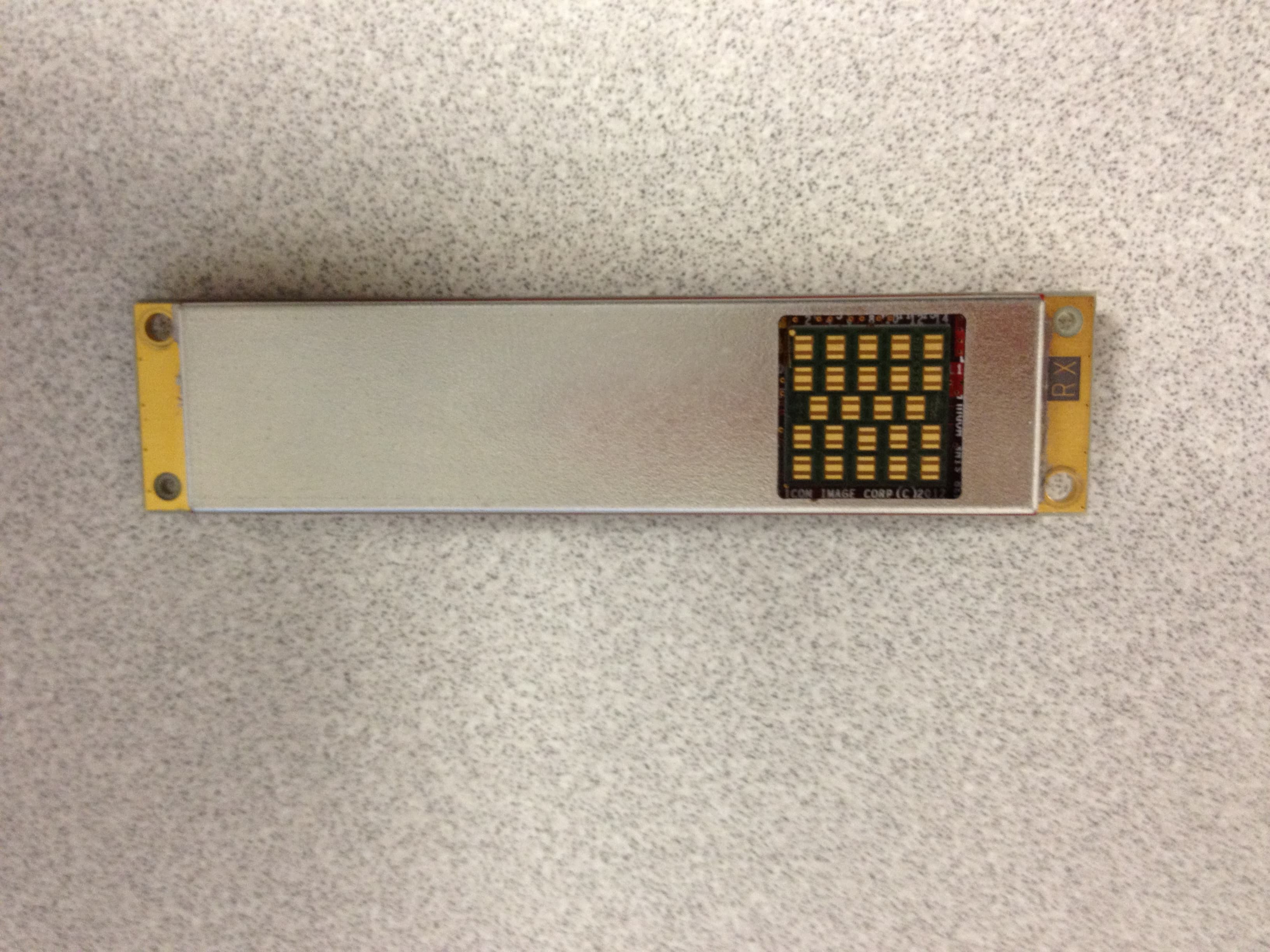
UK2-SII-SK63101
May 18, 2012wirelesshd receiver
Equipment Class
DXX - Part 15 Low Power Communication Device Transmitter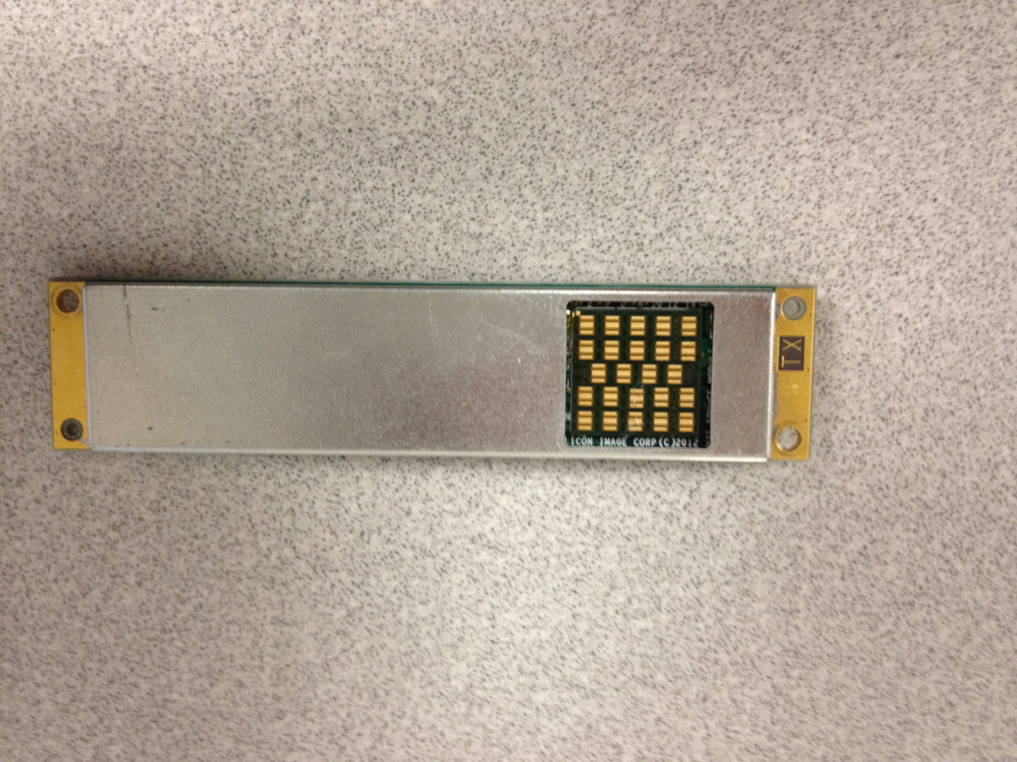
UK2-SII-SK63102
May 18, 2012wirelesshd transmitter
Equipment Class
DXX - Part 15 Low Power Communication Device Transmitter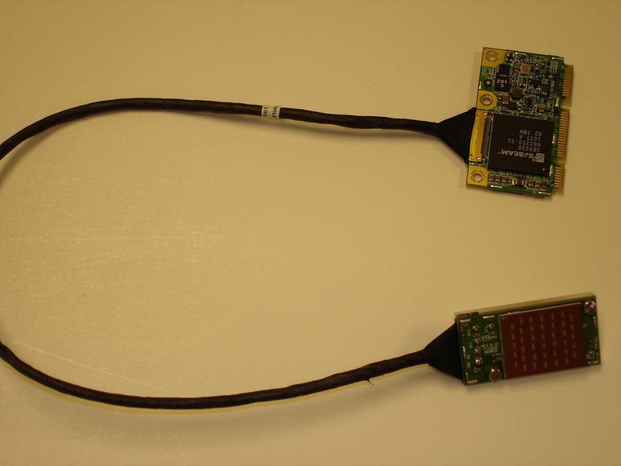
UK2-SK9210TX-HS
Nov 18, 201060GHz WirelessHD Display Mini Card Transmitter
Equipment Class
DXX - Part 15 Low Power Communication Device Transmitter